Page 919 of 1395
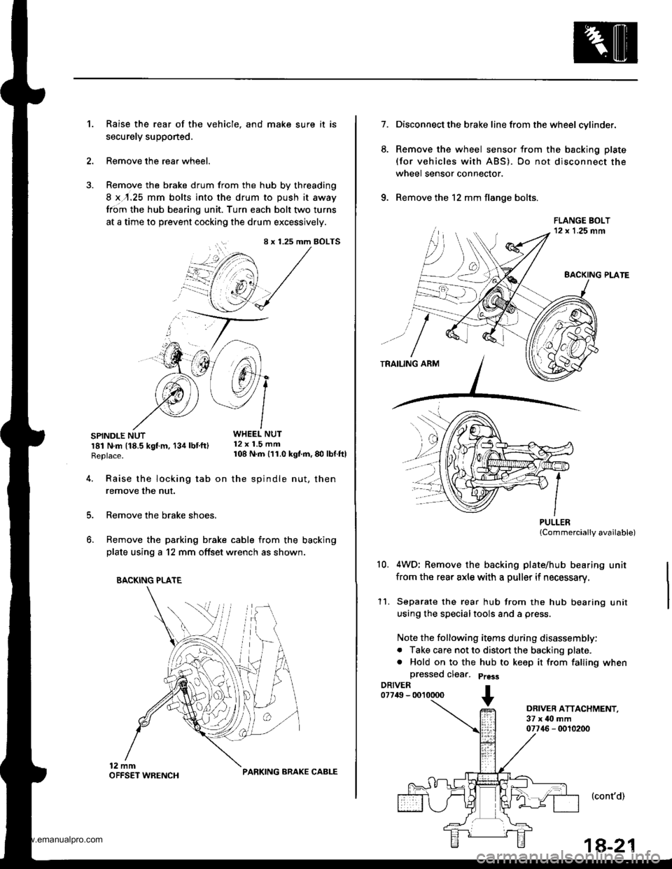
Raise the rear of the vehicle, and make sure it is
securely supponed.
Remove the rear wheel.
Remove the brake drum from the hub by threading
8 x,r.25 mm bolts into the drum to push it away
from the hub bearing unit. Turn each bolt two turns
at a time to prevent cocking the drum excessively.
SPINDLE NUTWHEEL NUT
r81 N.m t18.5 kgt m, 134 lbt'ftl 12 x 1.5 mm
Replace. 108 N m 111.0 kgf'm, 80 lbf ftl
't.
4.
8 x 1.25 mm BOLTS
i+/3 /',1
"@,1 /
.'--7 J-->-
5.
6.
Raise the locking tab on the spindle nut, then
remove the nut.
Remove the brake shoes.
Remove the parking brake cable from the backing
plate using a 12 mm offset wrench as shown.
BACKING PLATE
PARKING ARAKE CABLE
1a-21
7.
6.
Disconnect the brake line from the wheel cylinder.
Remove the wheel sensor from the backing plate
(for vehicles with ABS). Do not disconnect the
wheel sensor connector.
Remove the 12 mm flange bolts.
PULLERlCommercially available)
4WD; Remove the backing plate/hub bearing unit
from the rear axle with a puller if necessary.
Separate the rear hub from the hub bearing unit
using the specialtools and a press.
Note the following items during disassembly:
. Take care not to distort the backing plate.
. Hold on to the hub to keep it from falling when
a
10.
11.
DRIVER ATTACHMENT,37 x ilo mm07746 - 0010200
(cont'd)
www.emanualpro.com
Page 920 of 1395
Rear Suspension
Hub Bearing Unit Replacement (cont'd)
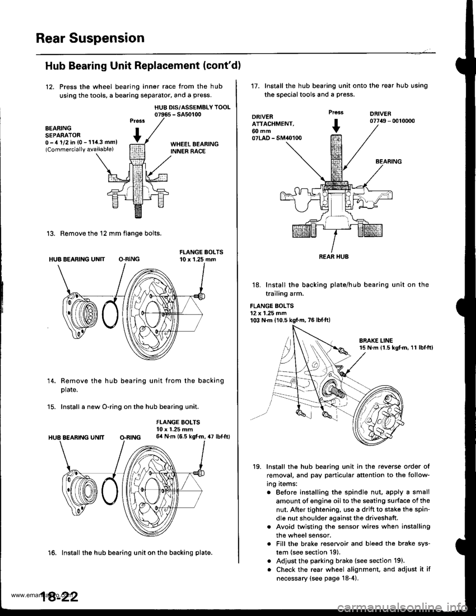
12, Press the wheel bearing inner race from the hub
using the tools, a bearing separator, and a press.
HUB DIS/ASSEMBLY TOOL07965 - SA50100
BEARINGSEPARATOR0 -,t 1/2 in {0 - 11i1.3 mml(Commercially qvailable)
13. Remove the 12 mm flange bolts.
HUB BEARING UN]T O.RING
14. Remove the hub bearing unit from the backing
plate.
15. Install a new O-ring on the hub bearing unit.
FLANGE BOLTS10 x 1.25 mm64 N.m (6.5 kgf.m, 47 lbf.ftl
16. Install the hub bearing unit on the backing plate.
18-22
't7.Install the hub bearing unit onto the rear hub using
the special tools and a press.
DRIVERATTACHMENT,60 mm07LAO - SM40100
Prcss
+
DRIVER07749 - 0010000
BEARING
18. Install the backing plate/hub
trailing arm.
FLANGE BOLTS12 x 1.25 mm103 N.m 110.5 kgf'm,75lbfft)
bearing unit on the
19. Install the hub bearing unit in the reverse order of
removal, and pay particular attention to the follow-
ing items:
. Before installing the spindle nut, apply a small
amount of engine oil to the seating surface of the
nut, After tightening, use a drift to stake the spin-
dle nut shoulder against the driveshaft.
. Avoid twisting the sensor wires when installing
the wheel sensor,
. Fill the brake reservoir and bleed the brake sys-
tem {see section 19).
. Adjust the parking brake (see section 191.
. Check the rear wheel alignment, and adjust it if
necessary (see page 18-4).
REAR HUB
www.emanualpro.com
Page 921 of 1395
Rear Damper
1.
Upper Arm Bushing Replacement
Remove the upper arm bushing and upper arminner bushing as shown.
UPPER ARM INNER BUSHING UPPER ARM AUSHIT{G
Mark a scribe line on the upper arm inner bushing
so it is in line with the bolt mounting surface.
BOLT MOUNTII{GSURFACE
Make a mark on the upper arm at two points so the
marks are in line and at a right angle with the arm
as shown in the drawing.
Drive in the upper arm inner bushing with themarks aligned until the leading edge is flush with
the uoDer arm.
Drive the upper arm bushing into the upper armuntil the leading edge is flush with the upper arm.
REAR UPPER ARM
5.
Removal
Remove the rear wheels (see page '18-21),
Remove the damper access panel and the damper
cap.
Remove the two flange nuts.
ACCESS PANEL
OAMPER CAP
't.
4. Remove the flange bolts.
Lower the rear suspension, and remove
damper.the
1a-23
www.emanualpro.com
Page 981 of 1395
Pulsers/Wheel Sensors
Wheel Sensor Replacement
NOTE;
. Be carefulwhen installing the sensors to avoid twisting the wires.
. The torque value of the bolts is 9.8 N.m ( 1.0 kgf.m, 7 Ibf.ft).
Front
6 mm BOLT9.8 N.m {1.0 kgtm. ?.2lbf'ft)
WHEEL SENSOR
Rgar
1. Remove the hub bearing unit (see section 18).
2. Remove the tour backing plate bolts.
3, Pull the backing plate away from the trailing arm, then remove the wheel sensor. lt is not necessary to disconnect the
brake line.
NOTE: This illustration shows the '97 - 98 models, The '99 - 00 models are similar.
6 mm BOLT9,8 N.m 11.0 kgf.m, 7.2lbf.ft)
\all
19-58
WHEEL SENSOR
www.emanualpro.com
Page 1080 of 1395
Rear Window Wiper Arm and
Motor Replacement
CAUTION: Put on gloves to protect your hands.
NOTE; Take care not to damage the rear hatch glass.
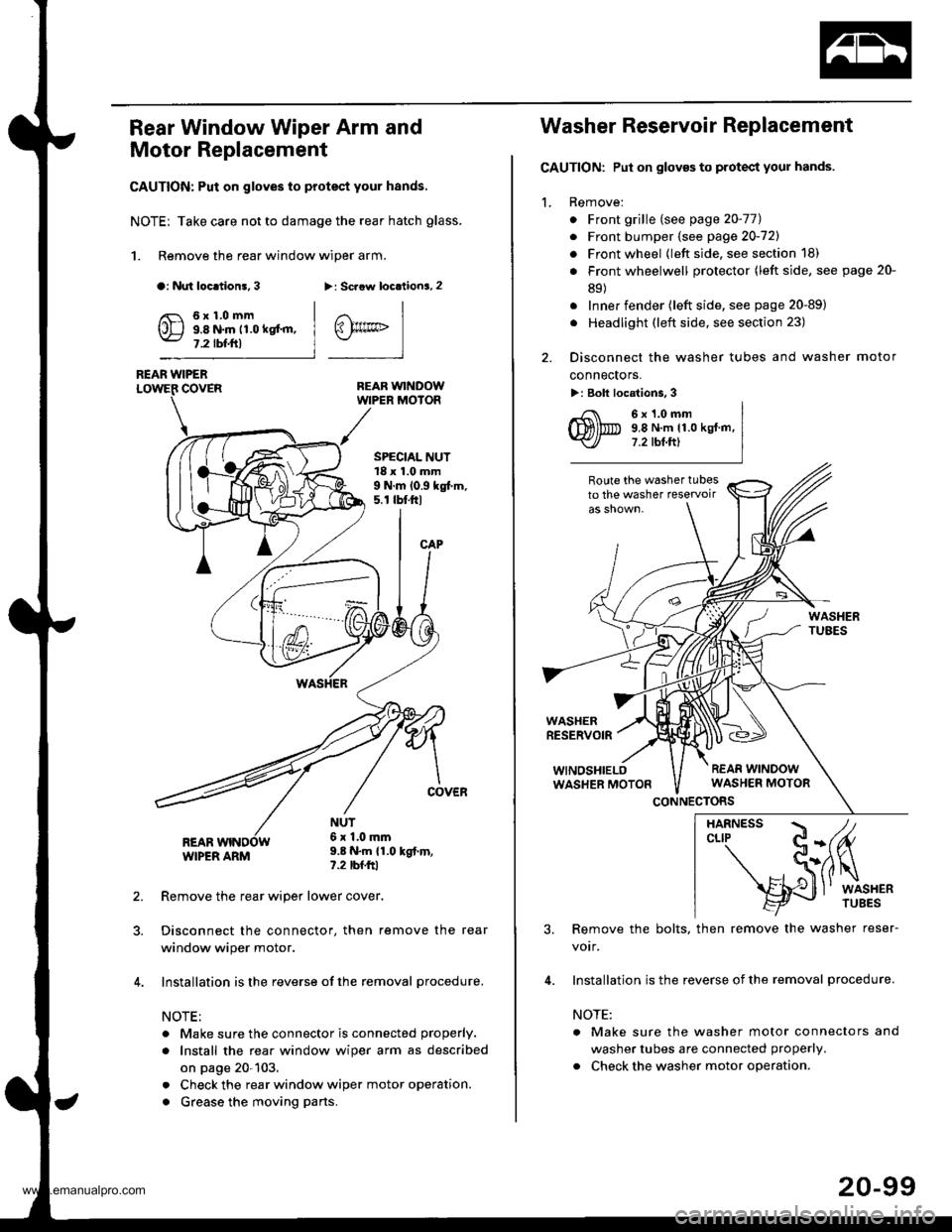
1. Remove the rear window wiper arm.
a: Nut loc.tion!, 3>: Scaow locationa, 2
REAR WINDOWWIPER MOIOR
REAR WIPERCOVER
REARWIPER ARM
6x1.0mm9.8 N.m 11.0 kgt'm,7.2 tbf.ftl
SPECIAL NUT18 x 1.0 mm9 N.m 10.9 kgt m,5. r tbt.ftl
NUT6x 1.0mm9.8 N.m {1.0 kgt.m,?.2 tbfftl
Remove the rear wiper lower cover.
Disconnect the connector, then remove the rear
window wiper motor.
Installation is the reverse of the removal procedure.
NOTE:
. Make sure the connector is connected properly.
. Install the rea. window wiper arm as described
on page 20-103.
. Check the rear window wiper motor operation.
. Grease the moving parts.
@rrc
Washer Reservoir Replacement
GAUTION: Put on gloves to protect your hands.
1. Remove:
. Front grille (see page 20-771
. Front bumper (see page 20-721
. Front wheel {left side, see section 18)
. Front wheelwell protector (left side, see page 20-
89)
. Inner fender (left side, see page 20-89)
. Headlight (left side, see section 23)
2. Disconnect the washer tubes and washer motor
connectors.
>: Bolt locations, 3
6x1.0mm9,8 N.m 11.0 kgt.m,7.2 tbt.ftl
Route the washer tubesto the washer teservoir
WASHERRESERVOIR
WINOSHIELOWASHER MOTON
CONNECTORS
3. Remove the bolts, then remove the washer reser-
votr,
4. Installation is the reverse of the removal procedure.
NOTE:
a Make sure the washer motor connectors and
washer tubes are connected properly.
. Check the washer motor operation.
HARNESS / tcLrP C-(fu
- S(ilq
s{J
l' wrsHER
20-99
www.emanualpro.com
Page 1384 of 1395
Driver's Airbag
1.
Replacement
After a collision in which the airbags were deployed, the
airbags, the seat belt tensioners (if so equipped), and
the SRS unit must be replaced.
@ Store a removed airbag with the pad su.-
tacs up, lf th€ airbag is improperly stored face down.
accidental deployment could propal the unit with
enough forc€ io causg serioug iniury.
CAUTION:
. Always disconnoct the drivor's airbag connector
when the SRS main harness is disconnactod.
. Do not disassemble or tamper with ihe airbag.
NOTE:
Do not install used SRS parts from another vehicle,
When repairing, use only new SRS parts.
Carefully inspect the airbag before you install it. Do
not install an airbag that shows signs of being
dropped or improperly handled, such as dents, cracks
or deformation.
Disconnect the battery negative cable, then discon-
nect the positive cable from the battery, and wait at
least three minutes.
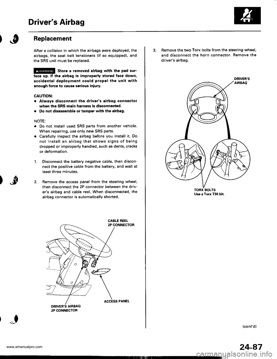
Remove the access panel from the steering wheel.
then disconnect the 2P connector between the driv-
er'6 airbag and cable reel. When disconnected. the
airbag connector is automatically shorted.
2P CONNECTON
ACCESS PANEL
24-87
3. Remove the two Torx bolts from the steering whsel,
and disconnect the horn connector. Remove the
driver's airbag,
(cont'd)
DRIVER'S
www.emanualpro.com
Page 1385 of 1395
Driver's Airbag
Replacement lcont'd)
CAUTION: 8. sure to instattthe SRS wiring so that it isnot plnched or inlerfsring with other parts.
4. Place the new driver's airbag into the steeringwheel, and secure it with new Torx bolts.
TORX EOLTS9.8 N,m 11.0 kgl.m, 7.2 tbf,ftlFeplace.
24-88,
5. Connect the driver's airbsg 2p connector to thecable reel 2P connector, then install the accesspanel on the steering wheel.
Connect the battery positive cable. then connect thenegative cable.
After installing the airbag assembly, confirm proper
system operation:
. Turn the ignition switch ON llt); the SRS indica-tor light should come on for about six secondsand then go off.. Mske sure both horn buttons work.o Take a test-drive, and make sure the cruise con-trol switches work.
7.
2P CONNECTOR
www.emanualpro.com
Page 1388 of 1395
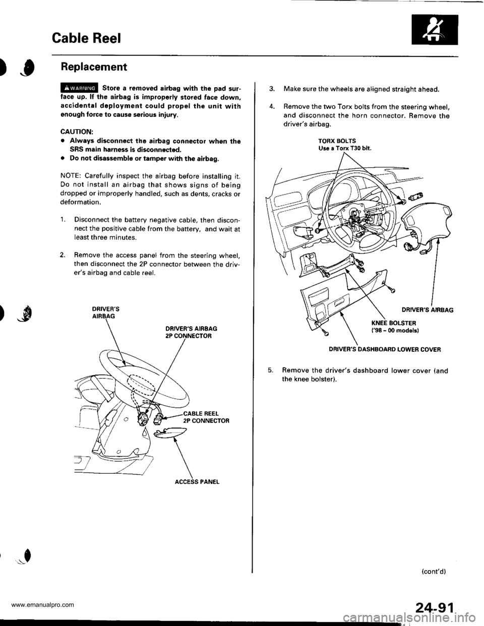
Cable Reel
)Replacement
@ stors a removed airbag with the pad sur-
tace up. lf th€ airbag is improperly stored face down,
accidental d6ployment could propel the unit withgnough force to cause serious iniuty.
CAUTION:
. Always disconnect the airbag connector whgn the
SRS msin harness is disconnoctod.
. Do not disassemblo or tamper with the airbag.
NOTE: Carefully inspect the airbag before installing it.
Do not install an airbag that shows signs of being
dropped or improperly handled, such as dents, cracks or
deformation,
'1.Disconnect the battery negative cable, then discon-
nect the positive cable from the battery, and wait at
least three minutes.
Remove the access panel from the steering wheel,
then disconnect the 2P connector between the driv-
er's airbag and cable reel.
*f
DRIVER'S
24-91
Make sure the wheels are aligned straight ahead.
Remove the two Torx bolts from the steering wheel,
and disconnect the horn connector, Remove the
driver's airbag,
TORX BOLTSUse a Torx T30 bit.
5. Remove the driver's dashboard lower cover (and
the knee bolster).
(cont'd)
DRIVER'S DASHBOARD LOWER COVER
www.emanualpro.com