1999 HONDA CR-V length
[x] Cancel search: lengthPage 715 of 1395

Regulator Valve Body
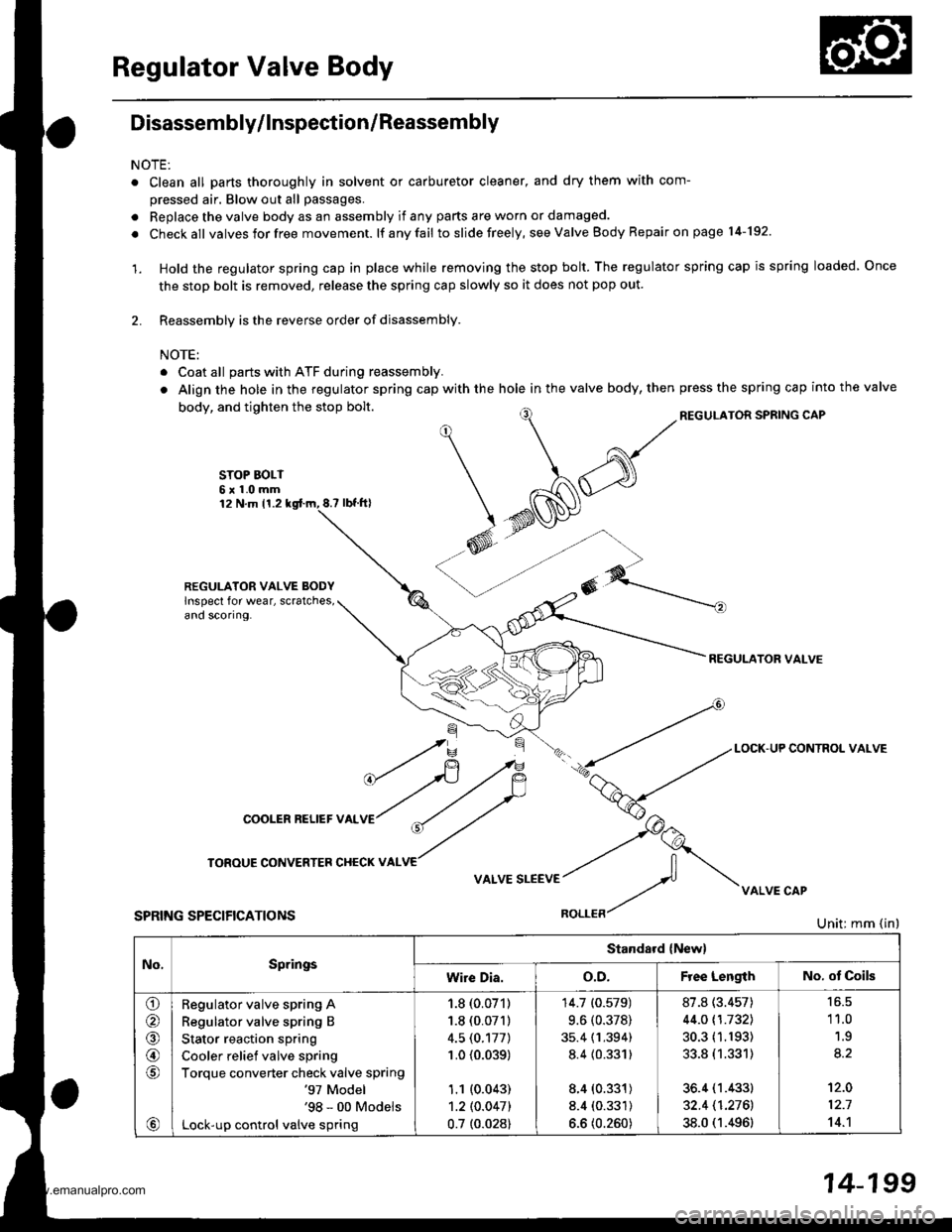
Disassembly/lnspection/Reassembly
NOTE:
o Clean all parts thoroughly in solvent or carburetor cleaner, and dry them with com-
pressed air. Blow out all passages.
. Replace the valve body as an assembly if any parts are worn or damaged.
. Checkall valvesforfree movement. lf anyfail toslidefreely, see Valve Body Repair on page l4-192.
'1. Hold the regulator spring cap in place while removing the stop bolt. The regulator spring cap is spring loaded Once
the stop bolt is removed, release the spring cap slowly so it does not pop out.
2. Reassembly is the reverse order of disassembly.
NOTE:
. Coat all parts with ATF during reassembly.
. Align the hole in the regulator spring cap with the hole in the valve body, thenpress the spring cap into the valve
REGULATOR SPSING CAPbody, and tighten the stop bolt.
STOP BOLT6x1.0mm12 N.m 11.28.? tbt.fil
REGULATOR VALVE BODYlnspect for wear, scratches,ano scoflng.
REGULATOR VALVE
No,SpringsStandard {New}
wire Dia.o.D.F ee LengthNo. ot Coils
o
@
@,6
a,
Regulator valve spring A
Regulator valve spring B
Stator reaction spring
Cooler relief valve spring
Torque converter check valve spring'97 Model'98 - 00 Models
Lock-up control valve spring
1.8 (0.071)
1.8 (0.071)
4.5 (0.177)
1.0 {0.039)
1.1 (0.043)
1.2lO.O47l
0.7 t0.028)
14.7 (0.579)
9.6 (0.378)
35.4 (1.394)
8.4 {0.331)
8.4 (0.331)
8.4 (0.331)
6.6 (0.260)
87.8 (3.457)
44.0 t1.7321
30.3 (1.193)
33.8 (1.331)
36.4 (1.433)
32.4 11.2761
38.0 (1.496)
'11.0
1.9
't2.0
12.7
14.'l
14-199
www.emanualpro.com
Page 717 of 1395

Lock-up Valve Body
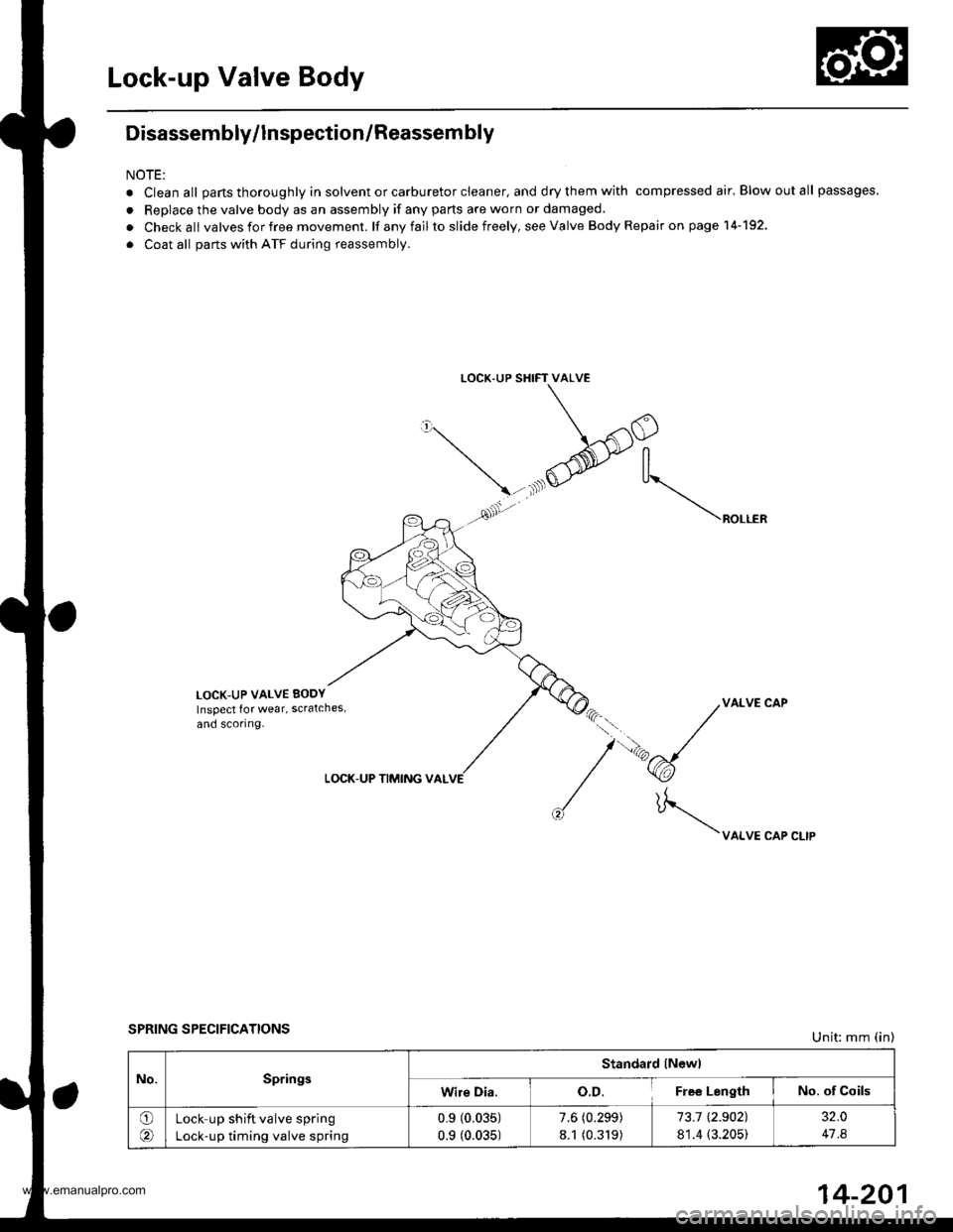
Disassembly/lnspection/Reassem bly
NOTE:
. Clean all parts thoroughly in solvent or carburetor cleaner, and dry them with compressed air. Blow out all passages.
. Replace the valve body as an assembly if any parts are worn or damaged.
. Checkall valvesforfree movement. lf anyfailto slide freely, seeValve Body Repairon page 14-192.
. Coat all parts with ATF during reassembly.
LOCK.UP SHIFT VALVE
\/'
\-.xlO
@-tr
, ^ ,As'. \"o...*
LOCK-UP VALVE EODY
Inspect lor wear, scratches,
and scoring.
VALVE CAP
\uo.*"or".,,
LOCK-UP TIMING VAL
SPRING SPECIFICATIONSUnit: mm (in)
No.SpringsStandard lNewl
Wire Dia.o.D.Fle€ LengthNo. of Coils
O(Lock up shift valve spring
Lock-up timing valve spring
0.9 (0.035)
0.9 (0.035)
7.6 (0.299)
8.1 (0.319)
73.1 t2.902),
81.4 (3.205)
32.0
47 .8
14-201
www.emanualpro.com
Page 825 of 1395

Front Driveshafts
Reassembly {cont'd)
7. Fit the inboard joint onto the driveshaft, and note
these items:
Reinstall the inboard joint onto the driveshaft by
aligning ths marks on the inboard joint with the
marks on the rollers.
Hold the driveshaft so the inboard joint points up
to prevent it from falling off.
Adjust the length of the driveshafts to the specifica-
tions shown. then adjust the boots to halfway
between full compression and full e)dension. Make
sure the ends of the boots seat in the grooves of the
driveshaft and Ioint.
/€\
/,?:..�{ \
t Sptine airection
lffi
tYl:\
ROLLER HOLDER
16-10
Left: 508 - 513 mm 120 - 2O.2 inl
Right: AT model 520 - 525 mm {20.5 - 20.7 in)
MT mod6l 515 - 520 mm (20.3 - 20.5 inl
II
-flm+dm@
9. Position the dynamic damper to the specifications
as snown.
Left: 299.5 t 2 mm 111.8 r O.l inl
Right: 299.5 t 2 mm 111.810.1 inl
OUTBOARO JOINT
www.emanualpro.com
Page 840 of 1395

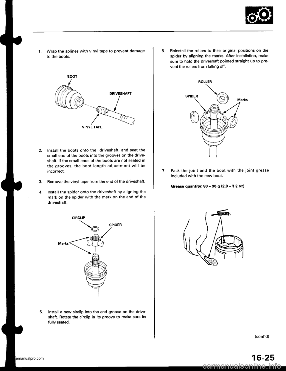
'1. Wrap the splines with vinyl tape to prevent damage
to the boots.
lnstall the boots onto the driveshaft, and seat the
small end of the boots into the grooves on the drive-
shaft, lf the small ends of the boots are not seated in
the grooves, the boot length adiustment will be
rncorrect.
Remove the vinyl tape from the end of the driveshaft.
Install the spider onto the driveshaft by aligning the
mark on the spider with the mark on the end of the
driveshaft.
lnstall a new circlip into the end g.oove on the drive-
shaft. Rotate the circlip in its groove to make sure its
fullv seated.
VINYL TAPE
6. Reinstall the rollers to their original positions on the
spider by aligning the marks. After installation, make
sure to hold the driveshaft pointed straight up to pre-
vent the rollers from falling off.
Pack the joint and the boot with the joint grease
included with the new boot.
Grease quantity: 80 - 90 s {2.8 - 3.2 o2)
7.
ROLLER
(cont'd)
16-25
www.emanualpro.com
Page 894 of 1395

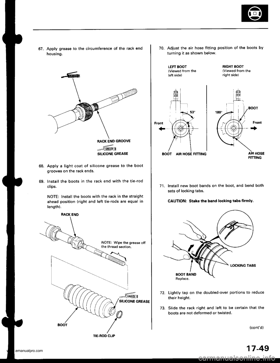
67. Apply grease to the circumference of the rack end
housing.
68.
69.
RACK END GROOVE
.={@
SILICONE GREASE
Apply a light coat of silicone grease to the boot
grooves on the rack ends.
lnstall the boots in the rack end with the tie-rod
clips.
NOTE: Install the boots with the rack in the straight
ahead position (right and left tie-rods are equal in
length).
RACK ENO
NOTE: Wipe the grease offthe thread section.
TIE.ROD CLIP
17-49
70. Adiust the air hose fitting position of the boots by
turning it as shown below.
LEFT BOOT{Viewed from theleft side)
+rom
''rT.a'.
, tri"
\,'tAr-
{,1@}tr
)Fr1
/\
RIGHT BOOT(Viewed trom theright side)
Front
+
BOOT AIR HOSE FITTING
71. Install new boot bands on the boot, and bend both
sets of locking tabs.
CAUTION: Stake the band locking tabs firmly.
Lightly tap on the doubled-over portions to reduce
their height.
Slide the rack right and left to be cenain that the
boots are not deformed or twisted.
(cont'd)
FIT'I'ING
www.emanualpro.com
Page 937 of 1395

Master Cylinder/Brake Booster
Removal/lnstallation
1, Disconnect the brake fluid level switch connectors.
2. Remove the reservoir cap from the master cylinder.
3. Remove the brake fluid from the master cvlinder
reservoir with a syringe.
4. Disconnect the brake lines from the master cylinder.
To prevent spills, cover the line joints with rags or
shop towels.
5. Remove the master cylinder mounting nuts and
wasners.
6. Remove the master cylinder from the brake booster.
CAUTION: Be careful not to bend or damage the
brake lines when removing the master cylinder.
Do not spill brake fluid on the vehicle; it may dam.
age the paint; it brake fluid does cont.ct the paint,
wash it oft immediately with water.
7. Disconnect the vacuum hose from the brake booster.
8. Remove the cotter pin and clevis pin from the clevis.
Do not disconnect the clevis by removing it from
the operating rod of the brake booster. lf the clevis
is loosened, adjust the pushrod length before
installing the brake booster (see page 19-15).
To Front Caliper (Without ABS)
\\
15 N.m {1.5 kgtm, vAcuuM HosE
r r rbf.ft) |
/ | BRAKE FLUTD LEvEL
/l /
swrrcHcoNNEcroRs
/ I I I COTTER PIN
I I / neotace
l,/-- ro Rear wheet cylinders / | I
h ./-''' /. I I IYli //*s (.S
I /r:
9. Remove the four booster mounting nuts.'10. Pull the brake booster forward until the clevis is
clear of the bulkhead.
11. Remove the brake booster from the enqine com-
panment.
12. Install the brake booster and master cylinder in the
reverse order of removal, and note these items:
. When connecting the brake lines, make sure that
there is no interference between the brake lines
and other parts.
. Be careful not to bend or damage the brake lines
when installing the master cylinder.
. lf replacing the master cylinder or brake booster,
check and adjust the pushrod clearance before
installing the master cylinder (see page 19-14).
Fill the master cylinder reservoir, and bleed the
brake system (see page 19-7).
After installation, check the brake pedal height and
brake pedal free play (see page 19-5), and adjust if
necessary.
13 N.m 11.3 kg{.m,I rbf.ft)
13.
14.
To Master Cylinder(Without ABS)To Modulator Unit(with ABs)@-\
\
^ To Front Caliper
9i\.
-#qCLEVIS PIN
):-,/
PROPORTIONING CONTROL VALVE
MASTER CYLINDER
15 N.m (1.5 kgf.m, 11 lbl.ftl
BRAXE BOOSTER
www.emanualpro.com
Page 939 of 1395

6.
7.
8.
lf the clearance between the gauge body and
adjusting nut is 0.4 mm (0.02 in), the pushrod-to-
piston clearance is 0 mm. However. if the clearance
between the gauge body and adjusting nut is 0 mm,
the pushrod-to-piston clearance is 0.4 mm (0.02 in)
or more. Therefore it must be adjusted and
recheck€d.
lf clearance is incorrect, loosen the star locknut, and
turn the adjuster in or out to adjust.
. Adjust the clearance while the specified vacuum
is applied to the booster.
. Hold the clevis while adjusting.
Tighten the star locknut securely.
Remove the special tool.
0 - 0.4 mm (0 - 0.02 inl
Adjust the pushrod length as shown if the
is removed,
booster
11610.5 mm{4.6 t 0.02 inl
PUSHRODLOCKNUT1.5N.m 11.5 kgf.m. '11 lbtfl)
Install the master cylinder (see page 19-13).
9.
STAR LOCKNUT22 N.m12.2 kgt m. 16 lbtftl
10.
(Check valve is built-in)
Brake Booster Inspection
FunctionalTest
1. With the engine stopped, press the brake pedal sev-
eral times to deplete the vacuum reservoir. thenpress the pedal hard, and hold it for 15 seconds. lf
the pedal sinks, either the master cylinder is
bypassing internally, or the brake system (master
cylinder, lines, modulator, proportioning valve. or
caliper) is leaking.
2. Start the engine with the pedal pressed. lf the pedal
sinks slightly. the vacuum booster is operating nor-
mally. lf the pedal height does not vary, the booster
or check valve is faultv.
3. With the engine running, press the brake pedal light-
ly. Apply just enough pressure to hold back auto-
matic transmission creep. lf the brake pedal sinks
more than 10 mm (3/8 in.) in three minutes, the mas-
ter cylinder is faulty. A slight change in pedal height
when the Ay'C compressor cycles on and off is nor-
mal. (The Ay'C compressor load changes the vacuum
available to the booster.)
Leak Test
1.Press the brake pedal with the engine running, then
stop the engine. lf the pedal height does not vary
while pressed for 30 seconds, the vacuum booster is
OK. lf the pedal rises, the booster is faulty.
With the engine stopped, press the brake pedal sev-
eral times using normal pressure. When the pedal is
first pressed. it should be low, On consecutive appli-
cations, the pedal height should gradually rise. lf thepedal position does not vary. check the booster
check valve.
Boostor Chock Valve Test
1. Disconnect the brake booster vacuum hose at the
booster.
2. Start the engine, and let it idle. There should be vac-
uum. lf no vacuum is available, the check valve is
not working properly. Replace the brake booster
vacuum hose and check valve. and retest.
ERAKE BOOSTERVACUUM HOSE
www.emanualpro.com