1999 HONDA CR-V drain bolt
[x] Cancel search: drain boltPage 697 of 1395
![HONDA CR-V 1999 RD1-RD3 / 1.G Workshop Manual
O END COVERiLl OIL SEAL Beplace.
O BALL BEARINGi.) A/T GEAR POSITION SWITCH COVER
i5] A/T GEAR POSITION SWITCH
aq) RoLLER
? COLLABi0 o-BtNG Replace.
€) FEED PIPE FLANGE
f,o) o-RING Replace.
1 SNAP HONDA CR-V 1999 RD1-RD3 / 1.G Workshop Manual
O END COVERiLl OIL SEAL Beplace.
O BALL BEARINGi.) A/T GEAR POSITION SWITCH COVER
i5] A/T GEAR POSITION SWITCH
aq) RoLLER
? COLLABi0 o-BtNG Replace.
€) FEED PIPE FLANGE
f,o) o-RING Replace.
1 SNAP](/manual-img/13/5778/w960_5778-696.png)
O END COVERiLl OIL SEAL Beplace.
O BALL BEARINGi.) A/T GEAR POSITION SWITCH COVER
i5] A/T GEAR POSITION SWITCH
aq) RoLLER
? COLLABi0 o-BtNG Replace.
€) FEED PIPE FLANGE
f,o) o-RING Replace.
1' SNAP RING
1A 3RD CLUTCH FEED PIPE
O COUNTERSHAFT LOCKNUT 23 x 1.25 mm Replace.
[} coNtcal SPRING WASHER Replace.iO PARK GEAR(!I ONE.WAY CLUTCH
E COUNTERSHAFT lST GEAR
@ NEEDLE BEARING
@ COUNTERSHAFT 1ST GEAR COLLAR
Or o-RtNGS Reptace.
?] lST CLUTCH FEED PIPE
@ o-RING Replace.
e3 FEED PIPE FLANGE
4I SNAP RING
€i DOWEL PINi?0 END COVER GASKET Replace.
?7) PARK PAWL STOP
E9 PARK PAWL
C9 PARK PAWL SPRING
€D PARK PAWL SHAFT
OI A/T GEAR POSITION SWITCH HARNESS CIAMP
@ PARK LEVER
€3 LoCK WASHER Replace.
04 PARK sToP Selective part(!' PARK LEVER SPRING
@ DRAIN PLUG
Ot SEALING WASHER Replace.
60 MA|NSHAFT LocKNuT 21 x 1.25 mm Replace.(9 CONICAL SPRING WASHER Replace.
@ lST CLUTCH ASSEMBLY
TOROUE SPECIFICATIONS
,!4! O-RING Replace.
@I THRUST WASHER@ THRUST NEEDLE BEARINGi.!' NEEDLE BEARINGi MAINSHAFT lST GEAR
@i MAINSHAFT 1ST GEAR COLLAR!r, O-RING Replace.iO COUNTERSHAFT SPEED SENSOR
E ROLLER
@, coLLAR
Ct o-RING Replace.5.] FEED PIPE FLANGE
09 o-RING Replace.
6A SNAP RING
5' IST.HOLD CLUTCH FEED PIPE
@-] SUB-SHAFT LOCKNUT 19 x 1.25 mm Replace.
!t CONICAL SPRING WASHER Replace.
6i' SUB-SHAFT lST GEAR
G) LINEAR SOLENOID ASSEMBLY(6!) LINEAR SOLENOID ASSEMBLY GASKET Replace
G] HARNESS BRACKET
6a SEALING WASHERS Replace.
C' ATF COOLER LINE
@ L|NE BoLT
GI ATF DIPSTICK
GI ATF COOLER LINE
O LINE BOLT
@ SEALING wasHERs Replace.aoo VEHICI.E SPEED SENSOR IVSS)
f,E O-RING Replace.
Bolt/Nut No.Torque ValueSizeRemarks
6A
6B
8A
12J'18D
195
21M
12 N.m (1.2 kgf.m,8.7 lbf.ft)
14 N.m (1.4 kgf.m, 10lbf.ft)
22 N.m 12.2 kgim, 16lbf.ft)
28 N.m (2.9 kgim,21 lbf.ft)
49 N'm (5.0 kgim,36 lbf.ft)
93 N.m (9.5 kgf.m,69 lbf.ft)
78 N.m (8.0 kgf.m,58 lbf.ft)
103+ 0+ 103 N{n (10.5 + 0+ 10.5 kSfm,
75.9' 0 - 75.9 lbfft)
6x1.0mm
6x1.0mm
8 x 1.25 mm
12 x 1 .25 mm
18 x 1.5 mm
19 x 1.25 mm
21 x 1.25 mm
23 x 1.25 mm
Line bolt
Drain plug
Sub-shaft locknut
Mainshaft locknut: Left-hand threads
Countershaft locknut: Left-hand
threads
14-181
www.emanualpro.com
Page 803 of 1395
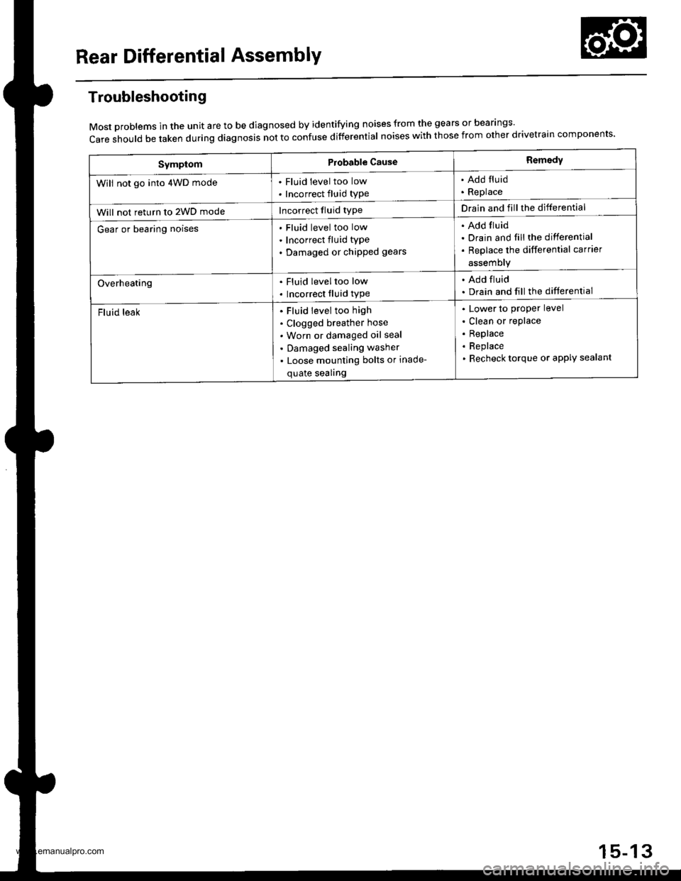
Rear Differential AssemblY
Troubleshooting
Most problems in the unit are to be diagnosed by identifying noises from the gears or bear'ngs'
care should be taken during diagnosis not to confuse differential noises with those from other drivetra'n components'
SymptomProbable CauseRemedy
Will not go into 4WD mode. Fluid level too low
. Incorrect fluid type
. Add fluid. Replace
Will not return to 2WD modeIncorrect fluid typeDrain and fill the differential
Gear or bearing noisesFluid level too low
Incorrect fluid type
Damaged or chipped gears
Add fluid
Drain and fill the differential
Replace the differential carrier
assemory
Overheating. Fluid leveltoo low
. Incorrect fluid type
. Add fluid. Drain and fill the differential
Fluid leakFluid level too high
Clogged breather hose
Worn or damaged oil seal
Damaged sealing washer
Loose mounting bolts or inade-
quate sealing
Lower to proper level
Clean or replace
Replace
Replace
Recheck torque or aPPIY sealant
15-13
www.emanualpro.com
Page 818 of 1395
DriveshaftsFront Driveshafts
Inspection
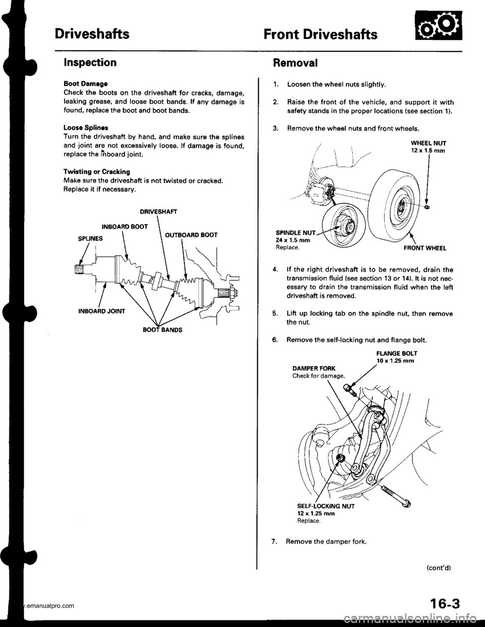
Boot Damago
Check the boots on the driveshaft for cracks, damago,
leaking grease, and loose boot bands. lf any damags is
found, replace the boot and boot bands.
Looso Splines
Turn the driveshaft by hand, and make sure th€ splin€s
and joint are not excessively loose. lf damage is found,
replace the inboard joint.
Twisting or Crscking
Make sure the driveshaft is not twisted or crackod.
Replace it if necessary.
DRIVESHAFT
1.
Removal
Loosen the wheel nuts slightly.
Raise the front of the vehicle, and suppon it with
safety stands in the proper locations (see section 1).
Remove the wheel nuts and front wheels.?
SPINDLE NUT24 x 1.5 mmReplace.
lf the right driveshaft is to be removed, drain the
transmission fluid {see s€ction 13 or 14). lt is not nec-
essary to drain the transmission fluid when the left
driveshaft is removed.
Lift up locking tab on the spindle nut, then remove
the nut,
Remove the self-locking nut and flange bolt,
FLANGE BOLT10 x 1.25 mm
FRONT WHEEL
(cont'd)
6.
SELF"LOCKING NUT12 x 1.25 mmReplace.
7. Remove the damper fork,
16-3
www.emanualpro.com
Page 833 of 1395
Front DriveshaftsIntermediate Shaft
Installation {cont'd}
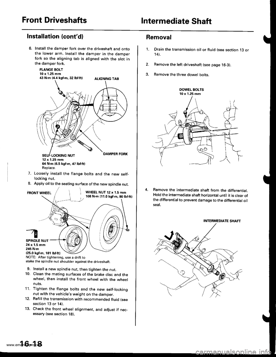
Install the damper fork over the driveshaft and ontothe lower arm. Install the damper in the damperfork so the aligning tab is aligned with the slot inthe damper fork.
FLANGE BOLT10 x 1.25 mm€ N.m {4.i1kst.n,32 lbf.ftl ALtcNtNG TAB
12x 1.25 mm64 N.m {6.5 kgf.m, 47 lbf.ftlReplace.
7. Loosely install the flange bolts and the new self-locking nut.
8. Apply oil to the seating surface of the new spindle nut.
FRONT WHEELi WHEEL NUT 12 x 1.5 mm108 N.m (11.0 kgf.m,80lbf.ftl
SPINDLE NUT24 x 1.5 mm245 N.m{25.0 ksf.m, 181 lbf.ft)NOTE: Atter tightening. use a drift tostake the spindle nut shoulder against the driveshaft.
9. Install a new spindle nut, then tighten the nut.10. Clean the mating surfaces of the brake disc and thewheel. then install the front wheel with the wheelnuts,
1'1. Tighten the flange bolts and the new setf-lockingnut with the vehicle's weight on the damper.12. Refill the transmission with recommended fluid (see
section 13 or 14).
13. Check the front wheel alignment. and adjust if nec-essary (see section 18).
16-18
1.
Removal
Drain the transmission oil or fluid (see section 13 or14).
Remove the left driveshaft (see page 16-3).
Remove the three dowel bolts.
Remove the intermediate shaft from the differential.Hold the intermediate shaft horizontal until it is clear ofthe differentialto prevent damage to the differential oilseal.
INTERMEDIATE SHAFT
www.emanualpro.com
Page 869 of 1395

Power Steering Pump
Replacement
1.Place a suitable container under the vehicle.
Drain the power steering fluid from the reservoir.
Remove the belt by loosening the pump mountingbolt and pump lock bolt.
PUMP MOUNNNG BOI.T24 N.m 12.4 kgt m, 17 lbl.ftl
PUMP LOCK BOLT24 N.m (2.4 kg{.m, 1, tbfttl
Cover the IVC compressor with several shop towelsto protect it from spilled power steering fluid.Disconnect the pump inlet hose and pump outlethose from the pump, and plug them. Take care notto spill the lluid on the body or parts. Wipe off anyspilled fluid at once.
Remove the pump mounting bolt and pump lockbolt, then remove the pump. Do not turn the steer-ing wheelwith the pump removed.
Cover the opening of the pump with a piece of tapeto prevent foreign materialfrom entering the pump.
PUMP OU'I.TT HOSE
11 N.m (1.1 kgf.m,E rbf.ti)
17-24
7.Connect the pump inlet hose and pump outlet hose.Tighten the pump fittings securely.
Loosely install the pump in the pump bracket withthe mounting bolt and lock bolt.
Install the pump belt.
Note these items du.ing belt instsllation:. Make sure that the power steering belt is proper-
ly positioned on the pulleys.
. Do not get power steering fluid or grease on thepower steering belt or pulley faces, Clean off anyfluid or grease before installation
FOWER STEER G EELT
PUTrlY
Adiust the pump belt (see page 17-141.
Fill the reservoir to the upper level line (see page't7 -151..
10.
'l l.
www.emanualpro.com
Page 876 of 1395
Power Steering Gearbox
Removal
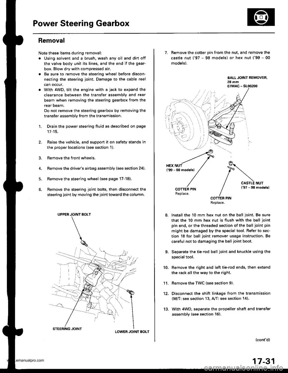
Note these items during removal:
. Using solvent and a brush, wash any oil and dirt off
the valve body unit its lines, and the end if the gear-
box. Blow dry with compressed air.
. Be sure to remove the steering wheel before discon-
necting the steering joint. Damage to the cable reel
can occur.
. With 4WD. tilt the engine with a jack to expand the
clearance between the transfer assembly and rear
beam when removing the steering gearbox from the
rear oeam.
Do not remove the steering gearbox by removing the
transfer assembly from the transmission.
1. Drain the power steering fluid as described on page'17-15.
Raise the vehicle, and suppon it on safety stands in
the proper locations (see section 1).
Remove the front wheels,
Remove the drive/s airbag assembly {see section 24).
Remove the steering wheel {see page 17-18).
Remove the steering joint bolts, then disconnect the
steering joint by moving the joint toward the column.
UPPER JOINT BOLT
LOWER JOINT BOLT
13.
7. Remove the cotter pin from the nut, and remove the
castle nut {'97 - 98 models) or hex nut ('99 - 00
models).
COTTER PINReplace.
Install the 10 mm hex nut on the ball joint. Be sure
that the 10 mm hex nut is flush with the ball joint
pin end, or the threaded section of the ball joint pin
might be damaged by the special tool. Refer to sec-
tion 18 for ball joint remover usage instruction, Be
careful not to damaging the ball joint boot.
Separate the tie-rod ball joint and knuckle using the
special tool.
Remove the right and left tie-rod ends, then extend
the rack all the way to the right.
Remove the TWC (see section 9).
Disconnect the shift linkage from the transmission
(M/T: see section 13, A/T: see section 14).
With 4WD. separate the propeller shaft and transfer
assembly (see section 161.
10.
11.
(cont'd)
17-31
www.emanualpro.com
Page 880 of 1395
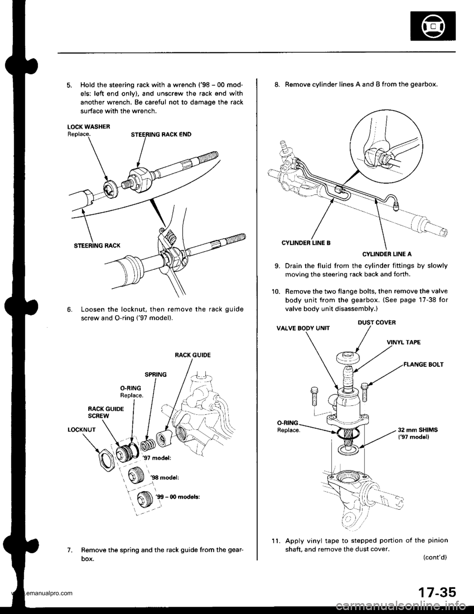
5. Hold the steering rack with a wrench {'98 - 00 mod-
els: left end onlv), and unscrew the rack end with
another wrench, Be careful not to damage the rack
surface with the wrench,
LOCK WASHER
Loosen the locknut, then remove the rack guide
screw and O-ring ('97 model).
6.
1.
LOCKNUT
Remove the spring and the rack guide from the gear-
DOX.
RACK GUIDE
9.
8. Remove cylinder lines A and B from the gearbox,
CYLINDER LINE A
Drain the fluid from the cylinder fittings by slowly
moving the steering rack back and {orth.
Remove the two tlange bolts, then remove the valve
body unit from the gearbox. (See page 17-38 for
valve body unit disassembly.)
VINYL TAPE
FLANGE BOLT
Apply vinyl tape to stepped portion of the pinion
shaft, and remove the dust cover.(cont'd)
DUST COVER
11.
17-35
www.emanualpro.com
Page 936 of 1395
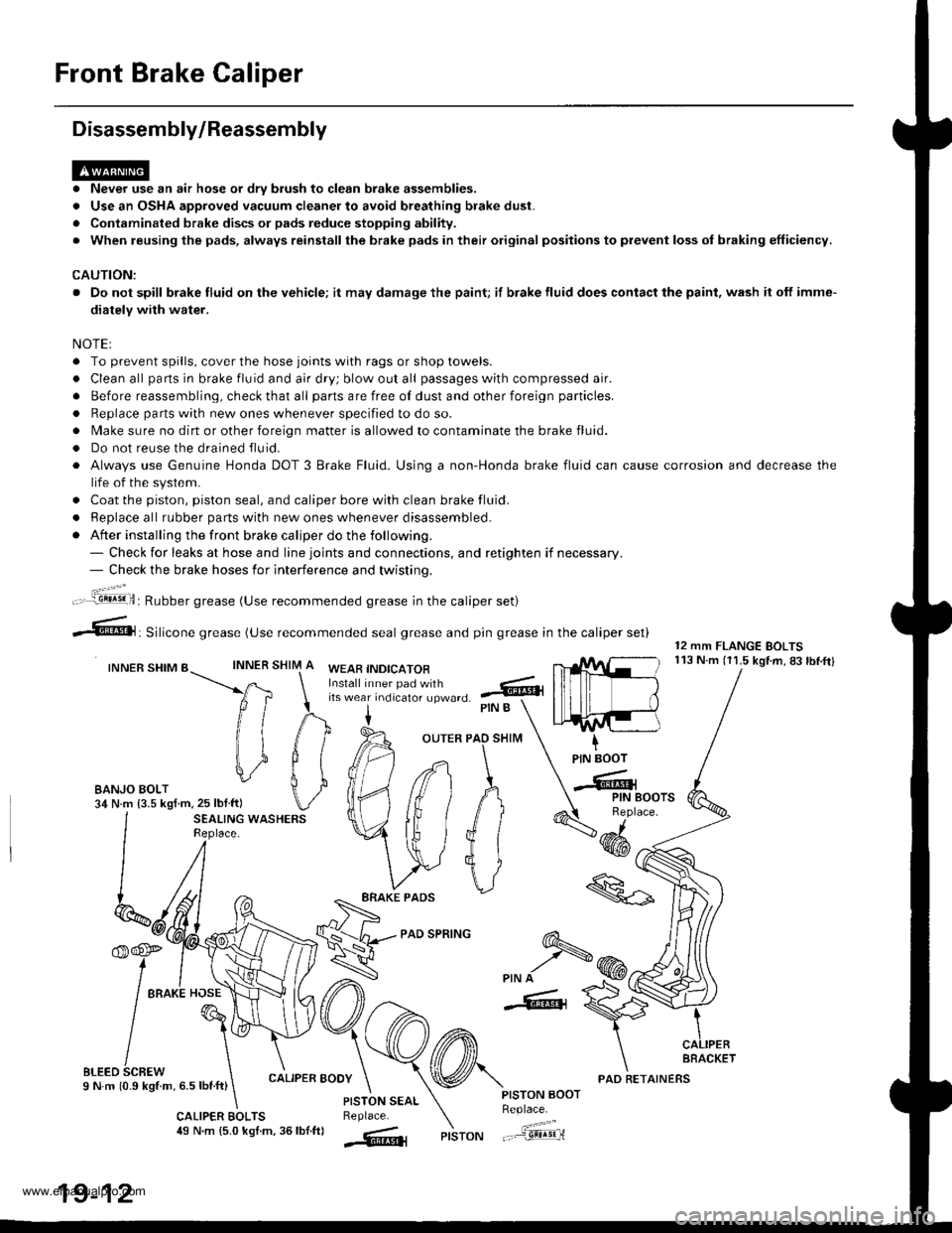
Front Brake Caliper
Disassembly/Reassembly
. Never use an air hose or dry brush to clean brake assemblies.
. Use an OSHA approved vacuum cleaner to avoid breathing brake dust.
. Contaminated brake discs or pads reduce stopping ability.
. When reusing the pads, always reinstallthe brake pads in their original positions to prevent loss ol braking efficiency.
CAUTION:
. Do not spill brake fluid on the vehicle; it may damage the paint; if brake fluid does contact the paint, wash it off imme-
diatelY with water.
NOTEI
. To prevent spills, cover the hose joints with rags or shop towels.
. Clean all pans in brake fluid and air dry; blow out all passages with compressed air.
. Before reassembling, check that all parts are free of dust and other foreign particles.
. Replace parts with new ones whenever specified to do so.
. Make sure no dirt or other foreign matter is allowed to contaminate the brake fluid.
. Do not reuse the drained fluid.
. Always use Genuine Honda DOT 3 Brake Fluid. Using a non-Honda brake fluid can cause corrosion and decrease the
life of the system.
. Coat the piston, piston seal, and caliper bore with clean brake fluid.
. ReDlace all rubber oarts with new ones whenever disassembled.
. After installing the front brake caliper do the following.- Check for leaks at hose and line joints and connections, and retighten if necessary.- Check the brake hoses for interference and twistinq.
SHIM
12 mm FLANGE BOLTS113 N.m (11.5 kgtm,83lbf.ftlINNER
ft
il1
#
\i
#
PIN B
OUTER PAO SHIM
PAD SPRING
IPIN BOOT
-Cr
SEALING WASHERSReplace.4dd*
ERAKE PADS
'f,-rre
/ tto*l "o"\
t@I
/\'
sLreo 6cnew \I N m 10.9 kStm, 6.5 lbnft)
\
6-
>PIN A
-6, {
CALIPER BOOY
CALIPER EOLTS49 N.m {5.0 kgl.m, 36lbf.ftl
PISTON AOOTReplace.
"..-a=a-...,--"sEqriPISTON
t".:jil,,.'.1!!!!9!il: Rubber grease (Use recommended grease in the caliper set)
irf"i:;;T::fl,-J'I",0 .@
--6, Silicone grease (use recommended seal grease and p,n grease in the caliper set)
INNER SHIM BWEAB INDICATOR
EANJO BOLT34 N.m {3.5 kgf m,25 lblftl
PISTON SEALReplace.
AFACKET
19-12
PAD RETAINERS
www.emanualpro.com