1999 HONDA CR-V diagnosis
[x] Cancel search: diagnosisPage 669 of 1395

Symptom-to-Component Chart
Hydraulic System
Before troubleshooting a problem on Hydraulic system, check the self-diagnosis Dl ('97 - 98) or Lq ('99 - 00) indicator
light indication. lf the El or E indicator light indicates a trouble code, perform the electrical troubleshooting according to
the Electrical System-to-Component Chart. lf the Ol or E indicator light does not indicate a trouble code and failure is not
found on the electrical troubleshooting, perform the hydraulic troubleshooting following the chart.
SYMPTOMCheck these items on the
PROBABLE CAUSE List
Check these items on
the NOTES List
Engine runs, but vehicle does not move in any gear.1r2FAt?82?K,L.R,S
Vehicle moves in El. @, but not in lE. E, E, or E, position6, 8, 9, 10, 29, 52c,M,o
Vehicle moves in [D!. E, E. E, E, but not in E] position.al
Vehicle moves in .&1, E. E, E, E, but not in E position4,6, 14, 15c,L.o
Vehicle moves in E position.10 , 12, 13, '�l4, '16, 2A, 32, 33, 34
Excessive idle vibration1,2, 18,3'1,35, 44, 46, 41B,K,L
Poor acceleration; flares on starting off in E, Di position
or E position
Stall rpm hish in El, El, E, E, E Position
Stall rpm hiqh in E, E, E, E position
1,2,3,6,37, 40K,L,R
6, 8, 10C,D
Stall rpm high in E positionc,D
Stall rpm high in hl position14N
Stall rpm low17,31, 44, 46, 47R
No shift18, 19, 39, 47, 48G,L
Fails to shift in Pr, E position or E position; from 1st to
3rd gear
21, 48
Fails to shift in EJ, E position or E position; from 1st to
4th gear
21,22, 47
Erratic upshifting
fz upshlft. ,3 ripshlft, 3r. up+ilft57
ffi20, 47
il21, 4A
3-4 upshift22, 47
Harsh upshift ('l-2)12, 18, 19,2A,49, 50, 56, 57
Harsh upshift (2-3)13, 1A, 19,23,26,28, 49, 50, 56, 57C,D.E,H,L
Harsh upshift {3-4)14,1A, 19,24,27,28, 49, 50, 56. 57C, D, E, I,L
Harsh downshitt (2-1)18, 19,23, 42,53,56,51o
Harsh downshift (3-2)12, 18,19,24,41,42, 54. 56, 57, 58
Harsh downshift (4-3)13,'1A, 19, 25, 41, 42, 55, 56, 57C, D, E, I
Flares on 2-3 upshift13,1A,19,23,26,50FI
Flares on 3-4 upshift14, 1A, 19,24,27,50E,L,N
Excessive shock on 2-3 upshift13. '18, 19 , 23, 26, 42, 49 , 50, 51E.L.N
Excessive shock on 3-4 upshift14, 1A, 19,24,27 , 42, 49,50,51E,L,N
Late shift from N position to ld or Erl position. or to E
position
10, 29M
Late shift from E position to E position4, 14,20,51o
Noise from transmission in all shift lever positions2,36K,L.O
Vehicle does not accelerate more than 3l mph (50 km/h).11
(cont'd)
14-153
www.emanualpro.com
Page 803 of 1395

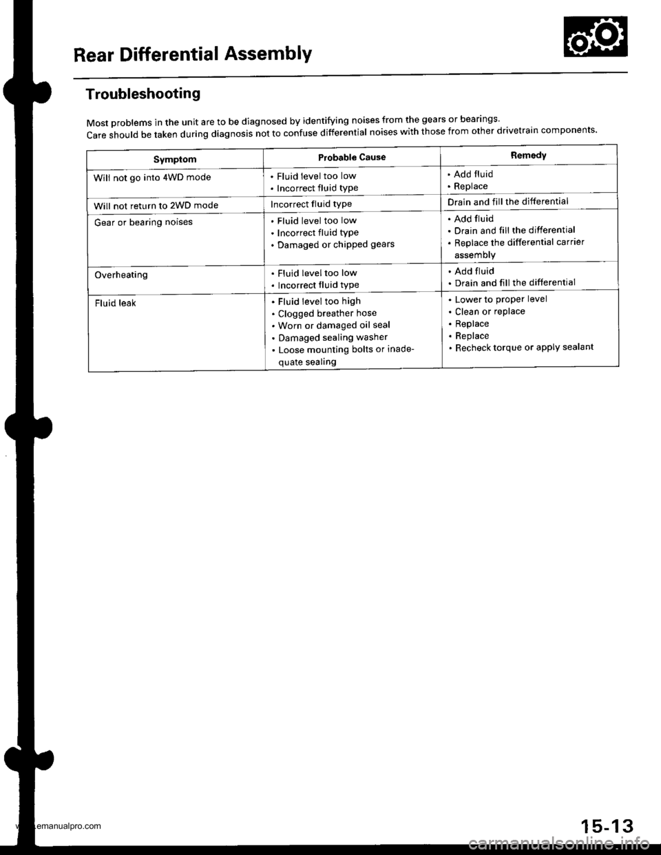
Rear Differential AssemblY
Troubleshooting
Most problems in the unit are to be diagnosed by identifying noises from the gears or bear'ngs'
care should be taken during diagnosis not to confuse differential noises with those from other drivetra'n components'
SymptomProbable CauseRemedy
Will not go into 4WD mode. Fluid level too low
. Incorrect fluid type
. Add fluid. Replace
Will not return to 2WD modeIncorrect fluid typeDrain and fill the differential
Gear or bearing noisesFluid level too low
Incorrect fluid type
Damaged or chipped gears
Add fluid
Drain and fill the differential
Replace the differential carrier
assemory
Overheating. Fluid leveltoo low
. Incorrect fluid type
. Add fluid. Drain and fill the differential
Fluid leakFluid level too high
Clogged breather hose
Worn or damaged oil seal
Damaged sealing washer
Loose mounting bolts or inade-
quate sealing
Lower to proper level
Clean or replace
Replace
Replace
Recheck torque or aPPIY sealant
15-13
www.emanualpro.com
Page 952 of 1395

ABS Control
The ABS control unit detects the wheel speed based on the wheel sensor signal it received, then it calculates the vehicle
speed based on the detected wheel speed. The control unit detects the vehicle speed during deceleration based on the
rate of deceleration.
The ABS control unit calculates the slip rate of each wheel, and it transmits the control signal to the modulator unit
solenoid valve when the slip rate is high
The pressure reduction control has three modes: pressure reducing, pressure retaining, and pressure intensi{ying modes.
Self-diagnosis Function
The ABS control unit is equipped with a main cPU and a sub cPU, that check each other for problems.
The CPUs check the circuit of the system.
When the CPUS detect failure, they shift to the "system down mode" or the "control inhibition mode".
The self-diagnosis can be classitied into these four categories:
O: Initial diagnosis
O: Except ABS control
O; During ABS control
@: During warning
On-board Diagnosis Function
The ABS system can be diagnosed with the Honda PGM Tester.
The ALB Checker cannot be used with this system. For air bleeding. and checking wheel sensor signals, use the Honda
PGIM Tester. See the Honda PGM Tester user's manuals for specific operating instructions.
(cont'd)
19-29
ABS CONTROL I-INIT
MODEABSINDICATOR LIGHTMAIN
RE LAY
SOLENOID
VALVERestan conditionDTC
SYSTEM
DOWNONNo
operatron
Drive
inhibitionOperation*rlgnition
switchOFF - oN (ll)Memory
CONTROL
INHIBITIONONNo
operaton
Drive
inhibitionOperationAutomaticlVemory
*1: Except CPU failure
www.emanualpro.com
Page 959 of 1395

Troubleshooting Precautions
ABS lndicalor
1 lf the system is oK, the ABS indicator goes off two seconds after turning the ignition switch oN 1l) wathout staningthe engine, and then comes on again and goes off after two seconds. This occurs because the ABS control unit isturned on by the lG2 power source.2. The ABS indicator comes on when the ABS control unit detects a problem in the system. However, even thouoh thesystem is operating properly, the ABs indicator will come on too, under the following conditions:. Signal disturbance
. Wheel spin
. Only drive wheels rotate. Battery voltage fluctuates
To determine the actual cause of the problem, question the customer about the problem, taking these conditions intoconsideration:
3 When a problem is detected and the ABS indicator comes on, the indicator can stay on until the ignition switch isturned OFF, or it can automatically go off, depending on the mode.. Indicator stays on untilthe ignition switch is turned off: When the system is in the system down mode.. Indicator automatically goes off: When the system is in the control inhibition mode.4 The ABS indicator stays on when the system is reactivated without erasing the DTC, but it goes off after starting thevehicle.
When the wheel sensor system is faulty and the ABS indicator comes on. the algorithm of the system automatically turnsoff the ABS indicator after the wheel speed signal returns to the normal speed. Also, when the DTc is erased, the cpu isreset and the ABS indicator goes off when the system checked out normal by the initial diagnosis.Therefore, test-drive the vehicle after servicing the wheel sensor system. and be sure that the ABS indicator does notcome on.
5 When the ABS control unit outputs battery voltage to the gauge assembly, the ABS indicator ooes off.
Diagnostic Trouble Code (DTCI
1. The diagnostic trouble code (DTc) is memorized when a problem is detected and the ABS indicator does not go off,or when the ABS indicator comes on.The DTc is not memorized when the ABS indicator comes on unress the cpu is activated,2 The memory can hold any number of DTCs. However, when the same DTc is detected twice or more, the tater one iswritten over the old one.
Therefore, when the same problem is detected repeatedly, it is recorded as one DTC.3. The DTCs are indicated in the order of ascending number, not in the order they occur.4. The DTCS are memorized in the EEPROM (non-volatile memorv).Therefore, the memorized DTcs cannot be canceled by disconnecting the battery. perform the specified procedures toerase the DTCS.
Self-diagnosis
1. Self-diagnosis can be classified into these four categories:' Initial diagnosis: Performed right after the eng ine starts and untir theABS indicator goes off.. Except ABS control: Performed when the ABS is not functioning.. During ABS control: Performed when the ABS is functioning.. During warning: Performed when the ABS indicator is ON.2. The system performs the fo|owing contrors when a probrem is detected by the serf-diagnosis:. ABS indicator ON. Memorv of DTC. Mode changetothe "system down mode,, or the ,,control inhibition mode,,.
MODEABS INDICATORMAIN
RELAY
SOLENOID
VALVECPURestart conditionDTC
SYSTEM
DOWNONNo
operation
Drive
inhibitionOperation*rlgnition
switchoFF - ON l)Memory
CONTROL
INHIBITIONONNo
operal|on
Drive
inhibitionOperationAutomaticlMemory
*1: Except CPU failure
19-36
www.emanualpro.com
Page 960 of 1395

Kickback'1. The motor operates when the ABS is functioning. and the fluid in the reservoir is forced out to the master cylinder,
causing kickback at the brake pedal.
2. The ABS control unit operates the solenoid valve when the brake pedal is released after the initial diagnosis You may
hear the solenoid valve operate at this time, but it is normal
Pumo Motol
1. The pump motor operates when the ABS is functioning
2. The ABS control unit checks the pump motor operation during acceleration. You may hear the motor operate at this
time, but it is normal.
Brake Fluid Replacement/Ail Bleeding
L Brake fluid replacement and air bleeding procedures are the same as for vehicles without ABS To ease bleeding, start
with the front wheels.
Troubleshooting
1. The troubleshooting flowchart procedures assume that the cause of the problem is still present and the ABS indicator
is still on. Following the flowchart when the ABS indicator does not come on can result in incorrect diagnosis.
2. Ouestion the customer about the conditions when the problem occurred, and try to reproduce the same conditions
for troubleshooting.
Self-diagnosis is made at various times such as the initial diagnosis, except ABS control, during ABS control, during
acceleration, during the specified vehicle speed, etc. Therefore, the symptom canngt be checked unless the check
conditions match with the problem conditjons
3. When the ABS jndicator does not come on during the test-drive. but troubleshooting is performed based on the DTC,
check lor loose connectors, poor contact of the terminals, etc., before you start troubleshooting.
4. After troubleshooting, erase the DTC and test-drive the vehicle. Be sure the ABS indicator does not come on.
5. The connector illustratjons show the female terminals with a single outline and the male terminals with a double out-
l ne.
ABS Function Test
To simulate ABS operation and activate the solenoid valves and pump, use the Honda PGM Tester.
Connect the PGM Tester to the 16P Data Link Connector (DLC). When the System Select menu is displayed, select the ABS
Test Mode menu, and follow the tester's prompts.
19-37
www.emanualpro.com
Page 963 of 1395

Diagnostic Trouble Code (DTC)
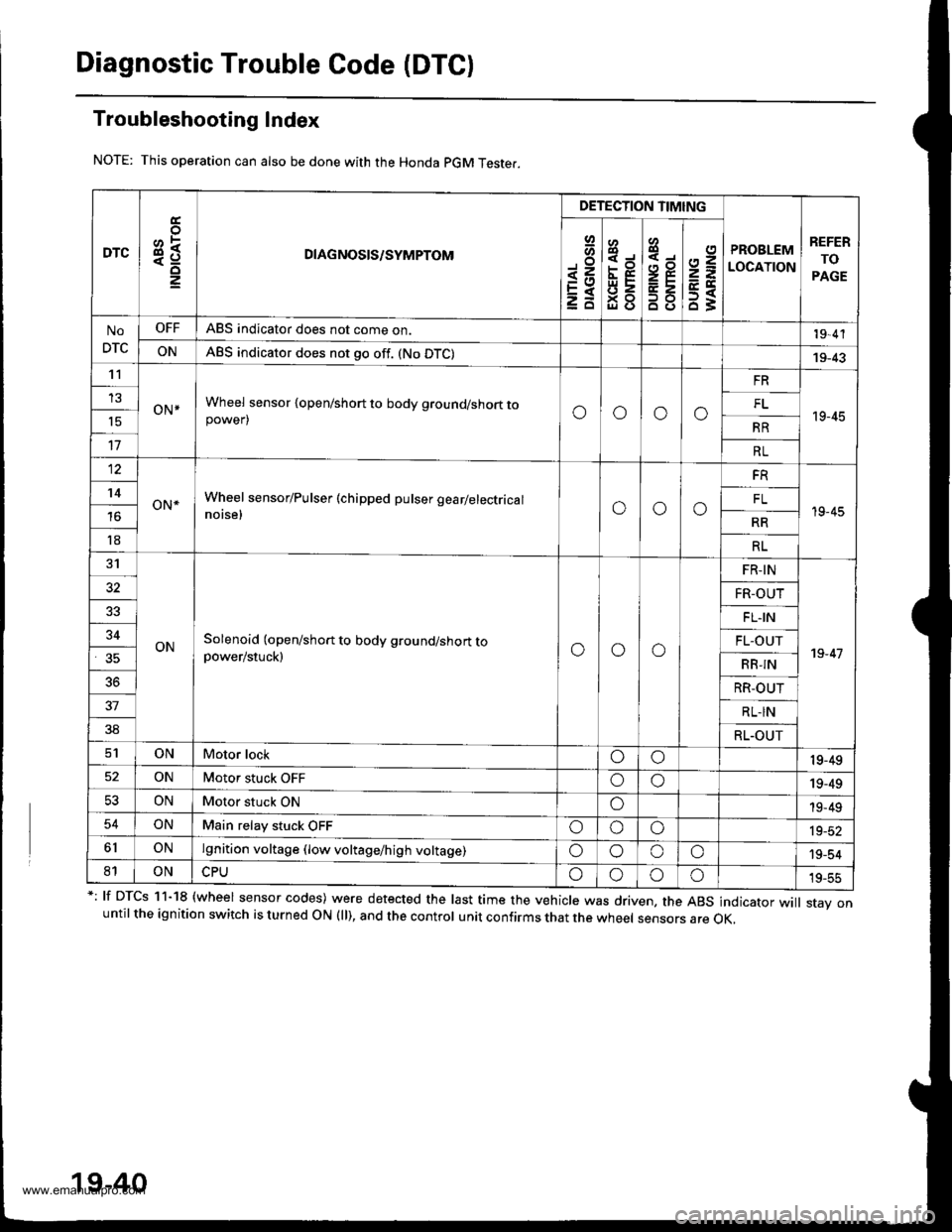
Troubleshooting Index
This operation can also be done with the Honda pGM Teste..
*: lf DTcs 11-18 {wheel sensor codes) were detected the last time the vehicle was driven, the ABs indicator wi
stav onuntil the ignition switch is turned ON (ll), and the control unit confirms that the wheel sensors are OK,
19-40
DTC3R
DETECTION TIMING
PROBLEM
LOCATION
REFER
TO
PAGE
Io
<=EXzd
8
93gl (J
4,,to
B8
2=
ET63
No
DTC
OFFABS indicator does not come on.19,4'l
ONABS indicator does not go off. (No DTC)19-43't1
oN*Wheel sensor {open/short to body ground/short topower)oooo
FR
19-45
13FL't5RR
17RL
12
oN*Wheel sensor/Pulser (chipped pulser gearlelectrical
notse,ooo
FR
19-45
't4FL
RR
18RL
31
ONSolenoid (open/short to body ground/short topower/stuck)ooo
FR-IN
19-47
32FR-OUT
FL.IN
34FL-OUT
RB-IN
36RR-OUT
37RL-IN
38RL.OUT
ONMotor lockoo19-49
ONMotor stuck OFFoo19-49
53ONMotor stuck ONo19-49
54ONMain relay stuck OFFoooia_at
6lONlgnition voltage (low voltage/high voltage)oooo'19-54
81ONoooo19-55
www.emanualpro.com
Page 1101 of 1395

Self-diagnosis Function
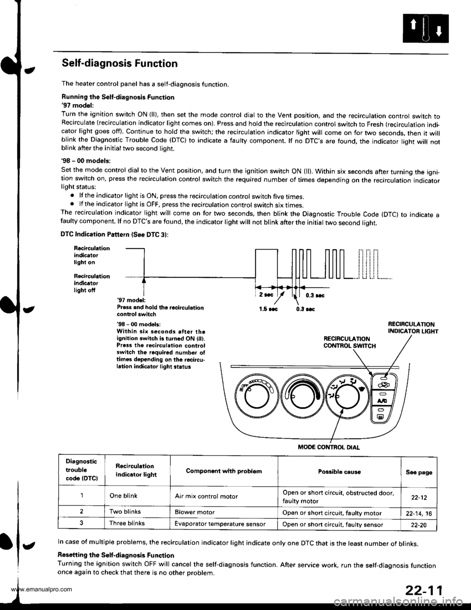
The heater control panel has a self-diagnosis function.
Running the Self-diagnosis Function'97 mod€l:
Turn the ignition switch ON {ll), then set the mode control dial to the Vent position, and the recirculation controt switch toRecirculate {recirculation indicator light comes on). Press and hold the recirculation control switch to Fresh (recirculation indi-cator light goes off). Continue to hold the switch; the recirculation indicator light will come on for two seconds. then it willblink the Diagnostic Trouble Code (DTC) to indicate a iaulty component. lf no DTC'S are found, the indicator liqht will notblink atter the initial two second light.
'98 - 00 models:
Set the mode control dial to the Vent position, and turn the ignition switch ON (ll). Within six seconds after turning the igni-tion switch on, press the recirculation control switch the required number of times depending on the recirculation indicatorlight status:
.lftheindicatorlightisON,presstherecirculationcontrol switch five times..lftheindicatorlightisOFF,presstherecirculationcontrol switch six I|mes.The recirculation indicator light will come on for two seconds, then blink the Diagnostic Trouble Code (DTC) to indicate afaulty component. lf no DTC'S are found, the indicator light will not blink after the initial two second liqht.
DTC Indicaiion Pattern {See DTC 3}:
Rocirculationindicatorlight on
Recirculrtionindicatorlighi off'97 model:P.ess and hold th6 recircul.tioncontrol switch'98 - 00 modek:Within six second3 atter theignition switch b turned ON (lll.Prass the rocirculation controlswitch the required number oltimes depending on the r6circu-lation indicator light striu3
,r*
/1.5 aaa 0.3 aac
RECIRCULANONINDICATOR LIGHT
In case of multiple problems, the recirculation indicator light indicate only one DTC that is the least number of blinks.
Resetiing the Solf.diagnosis Funqtion
Turning the ignition switch OFF will cancel the self-diagnosis function. After service work, run the self-diaqnosis functiononce again to check that there is no other Droblem.
MODE CONTROL OIAL
Diagnostic
trouble
code {DTCI
R6circulation
indicator lightComponent with problsmPossiblo causcSee page
'lOne blinkAir mix control molorOpen or short circuit, obstructed door,
faulty motor22-12
2Two blinksElower motorOpen or short circuit, faultv motor22-14,16
Three blinksEvaporator temperature sensorOpon or short circuit, faulty sensor22-20
t
www.emanualpro.com
Page 1102 of 1395

Troubleshooting
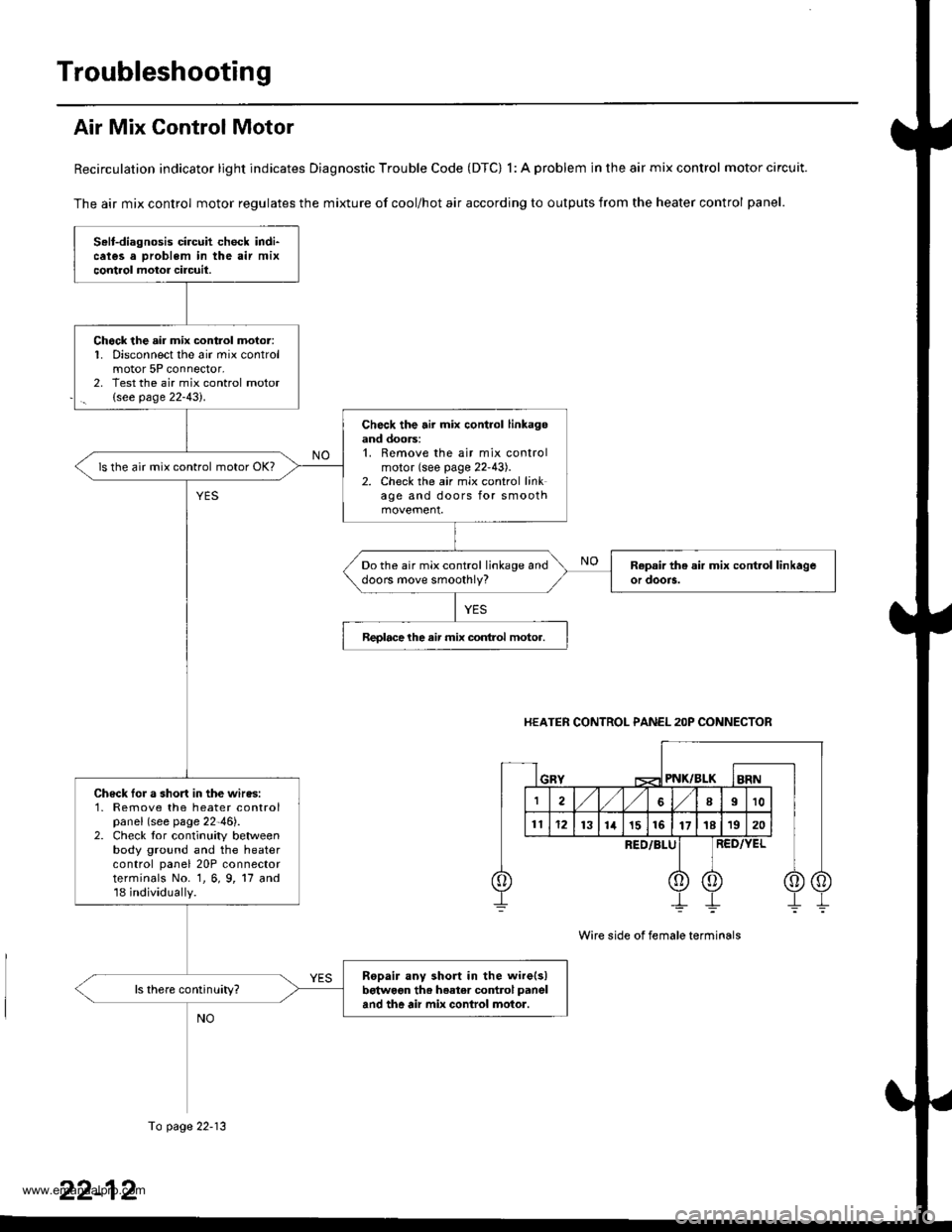
Air Mix Control Motor
Recirculation indicator light indicates Diagnostic Trouble Code (DTC) 1: A problem in the air mix control motor circuit.
The air mix control motor regulates the mixture of cool/hot air according to outputs from the heater control panel.
Selt-diagnosis circuit check indi-cates a Droblem in the air mixcontrol motor circuil.
Chock the air mix control moior:1. Disconnect the air mix controlmotor 5P connector,2, Test the air mix control motor(see page 22-43).
Check the air mix control linkagoand doors:1. Remove the air mix controlmotor (see page 22'43).2. Check the air mix control linkage and doors for smooth
ls the air mix control motor OK?
Do the air mix control linkage anddoors move smoothly?
Reolacelhe air mix conlrol motor.
Check Ior a short in the wires:1- Remove the heater controlpanel (see page 22-46).2. Check tor continuity betweenbody ground and the heatercontrol panel 20P connectorterminals No. 1, 6, 9, 17 and18 individually.
Ropair any short in the wire(s)betwoon th. heater co.rtrol panel
and the air mix conlrol motor.
HEATER CONTROL PANEL 2OP CONNECTOR
PNK/BLK
RED/BLU
Wire side of female terminals
To page 22-13
www.emanualpro.com