Page 409 of 1395
Chack iho EVAP purge controlsolenoid valve:1. Disconnect the vacuum hosetrom the EVAP controlcanister.2, Connect the vacuum pump tothe hose and apply vacuum,
Does it hold vacuum?
Chgck thg EVAP control csnbter:1. Reconnect the vacuum hose tothe EVAP control canister.2. Connect a vac!um gauge tothe purge air hose.3. Connect PCM connector terminals A15 and 410 with ajumper wire.4. Stan the engine.5. Check the vacuum.
Check the EVAP two way valve(see page 11'224).
Does the EVAP two way valvework properly?Rapbce the EVAP two wey valve.
Substitute a known-good PCMand rechock. It symptom/indica-tion gocs away, roplacg tho origi-nrl rcM.
(From page 11-206)
JUMPEF WIRE
<\
EVAP CONTNOLCANISTER
VACUUMPUMPIGAUGE,0-30 in.Hg4973X -
0il1 -
xxxxx
VACUUM/PRESSUREGAUGE0-4 in.Hg07JA2 - ml(x)o8
wire side of female terminals
{cont'd)
-20711
www.emanualpro.com
Page 410 of 1395

Emission Control System
Evaporative Emission (EVAP) Controls (cont'd)
99 - 00 models:
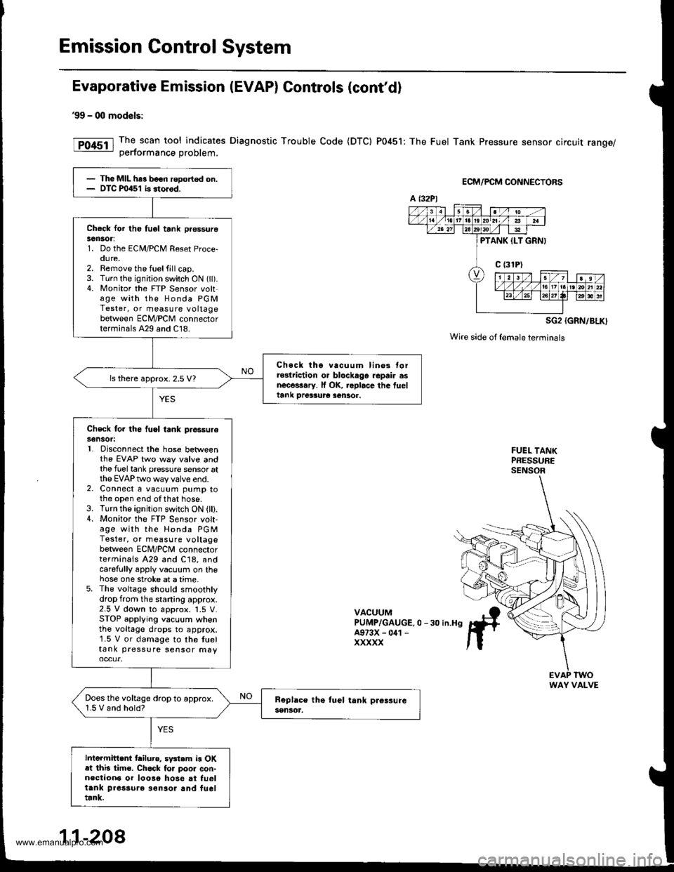
The scan tool indicates Diagnostic Trouble Code {DTC) P0451: The Fuel Tank Pressure sensor circuit range/oerformance Droblem.
ECM/PCM CONNECTORS
SG2 {GRN/BLK)
Wire side of {emaleterminals
FUEL TANKPRESSURESENSOR
VACUUMPUMP/GAUGE.0 -30 in.H9A973X - 041 -
XXXXX
- The MIL har been rooort€d on.- DTC P0451 b storod.
Check lor th6 tu6l tank pr€ssurelen30r:1. Do the ECM/PCM Reset Proce,oure.2. Remove the fuelfill cap.3. Turn the ignition switch ON (ll).4. Monitor the FTP Sensor voltage with the Honda PGMTester, or measure voltagebetween ECM/PCM connectorterminals A29 and C18.
Chock tho vacuum lin6s torrGlriction o. blockago repair asnecessary. lf OK, roplace the fueltank Drer3ur€ sentor.
ls there approx. 2.5 V?
Check for the fuel tank piessureSensot:L Disconnect the hose betweenthe EVAP two way valve andthe fuel tank pressure sensor atthe EVAP two way valve end.2. Connect a vacuum pump tothe open end ofthat hose.3. Turn the ignition switch ON (lll.4. Monitor the FTP S€nsor volt-age with the Honda PGMTester, or measure voltagebetween ECNI/PCNI connectorterminals A29 and C18, andcarefully appiy vacuum on thehose one stroke at a time.5. The voltage should smoothlydrop from the staning approx.2.5 V down to approx. 1.5 V.STOP applying vacuum whenthe voltage drops to approx.1.5 V or damage to the tueltank pressure sensor may
Does the voltage drop to approx.1.5 V and hold?
Intermittent tailuro. sv3tem is OKat this tim€. Chack to. poor con-n€ction6 or 10036 hose at fu6ltank pres3ure ionsor and fueltrnk.
a t32Pl
PTANK ILT GRNI
WAY VALVE
11-208
www.emanualpro.com
Page 417 of 1395

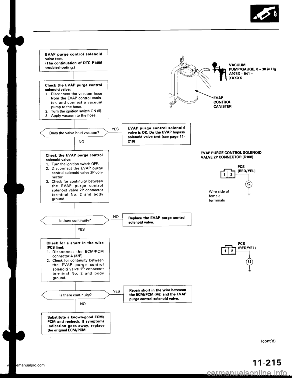
EVAP purge control 3ol€noidvalve test.{Tho continu.tion of DTC Plil56
trouble3hootin9.)
Check the EVAP purge control
solenoid valve:1. Disconnect the vacuum hosetrom the EVAP control canis-
ter, and connect a vacuumpump to the hose.2. Turn the ignition switch ON (ll).
3. Apply vacuum to the hose.
EVAP purge contlol solenoidv.lvo is OK. Do the EVAP bypai3
solenoid valve test (see Page 11-
2161
Does the valve hold vacuum?
Check tho EVAP purge control
solenoid valve:'t. Turn the ignition switch OFF.2. Disconnect the EVAP Purgecontrol solenoid valve 2P con-nector,3. Check for continuity between
the EVAP pu rge controlsolenoid valve 2P connectorterminal No.2 and bodYground,
Check for s short in the wire
{PCS linel:1. D iscon nect the ECM/PCMconnector A {32P).2. Check for continuity betweenthe EVAP purge controlsolenoid valve 2P connectorterminal No. 2 and bodyground.
neprir short in tho wite bot$reon
the ECM/FCM lAGl and thc EVAPpurge control 3olenoid valve.ls there continuity?
Substitut€ a known-good ECM/
PCM and recheck. lf symptom/indication goe3 away. repl.ce
thc originsl ECM/PCM.
VACUUMPUMP/GAUGE,0 - 30 in.HgA973X - 041 -
xxxxx
EVAPCONTROLCANISTER
EVAP PURGE CONTROL SOLENOIDVALVE 2P CONNECTOR (Cl08}
Wire side offemaleterminals
(cont'd)
-21511
www.emanualpro.com
Page 424 of 1395

Emission Control System
Evaporative Emission (EVAP) Controls (cont,dl
lT145il ("ont'o)
EVAPTHREE
VATVE \'t
VACUUMPUMP/GAUGE,0 - 30 in.HsA973X - 041 -
xxxxx
WIRE
ECM/PCM CONNECTOR A {32PI
vsv
Wire side of female terminals
EVAPCONTROLCANISTER
EVAP CONTROLCANISTER VENT SHUTVALVE 2P CONNECTOR {C361}
riErr+J
I vsv
/A {Lr GRN/WHT|
YI
Wire side of female terminals
CANISTEFVENTSHUTVALVE
EVAPCONTROL
(}BING
Replace.
ffilrcr
e
(BLK/wHr)
I
11-222
EVAP control canistor vent shutvalve t6t.(The continuation of DTC p1457
troubl€ahooting.)
Chcck the EVAP control c.nirt6lvent ahut vrlve:1. Disconnect the vacuum hosetrom the EVAP thre€ way valve,and connect a vacuum pumpto the hose.2. Connect the ECM,PCM conn6c,tor terminal A4 to the bodyground with a jumper wire.3. Turn the ignition switch ON fil).4. Applyvacuum to the hose.
EVAP control crni3ter v6nt shutvelve b OK. Do the canistsr sys-lern loak test {3ee page 11-2231.
Does the valve hold vacuum?
Check for an open in the wireIVSV linGll1. Turn the ignition swjtch OFF.2. Disconnect the EVAP controlcanister vent shut valve 2pconnector.3. Check for continuity betweenthe EVAP control canister ventshul valve 2P connector termi-nal No. l and body ground.
Ropril op6n in tho wire botweonthe EVAP control canister v6ntshut v.lve and the ECM/PCM(A41.
Check tor an open in the wire(lGl line):1. Turn the ignition switch ON l).2. Measure voltage between theEVAP control canister vent shutvalve 2P connector terrninalNo. 1 and body ground.
Roplace thG EVAP cont.ol canis-ter Yent shut velve and O-ring.
Repai. opon in the wire betwoenth6 EVAP control canister vontshut valve .nd No. 15 ALTERNA-TOB SP SENSOR t?.5 Alfus6.
{LT GRN/WHT)
36a10
l4/1617l8't9202l232426 272a2930
JUMPER
www.emanualpro.com
Page 590 of 1395

Electrical Troubleshooting ('97 Model)
Troubleshooting Flowchart - Shift Control Solenoid Valve B
Po33ibla Crusa
. Disconnec{ed shift cont.ol solenoidvalve A/B dssombly connector. Short or open in shift conlrol sole-noid valvg B wire' Faultv shift comrol 3olenoid valvo B
lf the Honda PGMT€ster is available:
PCM CONNECTORS
Wire side ot female terminals
. OBO ll Scan Toot indicrt8 CodoP0758.. Setf-diagnGis E indicator lightblinks oight tim93.
Check and r€cord the lreere datain case it is needed later for prob
lem verilication.
Test solenoid valve B with theHonda PGM Tester in the FLrnction test mode.
The 3olonoid is OK at this time.Verifv that all connoctors in thecircuit are making good contlct.Did the solenoid Dass the test?
Chock tor a Sho.t to Power:1. Turn the ignition switch OFF.2. Disconnect the A (32P) and B{25P) connectors Irom the PCM.3. Turn the ignition switch ON (ll).
4. Measuro the voltage botveenthe 811 and Ag or A22 termi-nats.
R.p.ir 3hort to power in the wirebotwo€n the 811 iormin.l andtho shift control sol.noid valve B.
M.6sure Shift Control SolonoidValve B Reaistanco:1. Turn the ignition switch OFF.2. Measure the r€sistancebetween the 811 and A9 orA22 terminals.
Checl lor loosc terminal fil in thePCM connactors. It nocessarv,substitute a known-good aole-noid vllvo asssmbly or PCM andr6chsck,
ls the resistance 12 - 25 O?
To page 14-75
14-74
www.emanualpro.com
Page 599 of 1395

From page 14 82
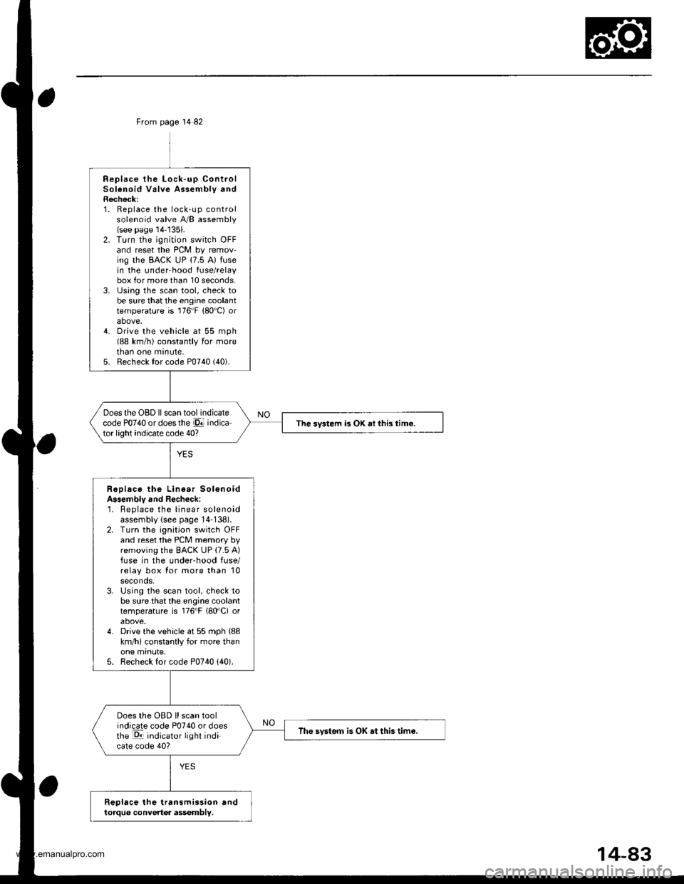
Replace the Lock-up ControlSolenoid Valve Assembly andRecheck:1. Replace the lock-up controlsolenoid valve A/B assembly(see page 14-'135).2. Turn the ignition switch OFFand reset the PCM by remov-ing the BACK uP (7.5 A) fusein the under-hood fuse/relaybox for more than 10 seconds.3. lJsing the scan tool, check tobe sure that the engine coolanttemperature is 176"F 180'C) orabove,4. Drive the vehicle at 55 mph(88 km/h) constantly for moretnan one mrnute.5. Recheck for code P0740 (40).
Does the OBD ll scan tool indicatecode PO74O or doesthe El indicator light indicate code 40?The svstem is OK ai this time.
Replace the Linear Sol€noidA$embly and Recheck:'1. Beplace the linear solenoidassembly {see page 14-138).2. Turn the ignition switch OFFand reset the PCM memory byremoving the BACK UP (7.5 A)fuse in the underhood fuse/relay box for more than 10seconds.3. Using the scan tool, check tobe sure that the engine coolanttemperature is 176"F (80'C) orabove.4. Drive the vehicle at 55 mph (88
km/h) constantly for more thanone minute,5. Recheck for code P0740 {40).
Does the OBD ll scan toolindicate code P0740 or doesthe E indicator light indicate code 40?
The svsteo is OK at this tim€.
Replace the transmission andtorque convertor assembly.
www.emanualpro.com
Page 601 of 1395

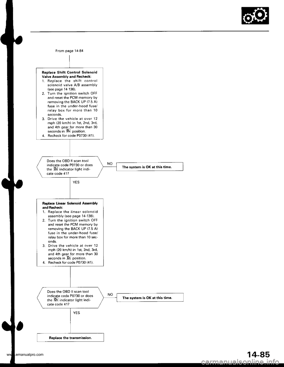
Replace Shift Control Solenoidvslve Assembly and Recheck:1. Replace the shift controlsolenoid valve A/B assembly(see page'14 136).2. Turn the ignition switch OFFand reset the PCM memory byremoving the BACK UP (7.5 A)fuse in the under-hood fuse/relay box for more than 10seconds.3. Drive the vehicle at over 12mph (20 km/h) in 1st,2nd,3rd,and 4th qear for more than 30seconds in E position.
4. Recheck for code P0730 (41).
Does the OBD ll scan toolindicate code P0730 or doesthe E indicator light indicate code 41?
The svstem is OK at this time.
Replace Linea. Solenoid Ass€mblyand Recheck:1. Replace the linear solenoidassembly lsee page 14-138).2. Turn the ignition switch OFFand reset the PcM memory byremoving the BACK UP 17.5 A)fuse in the underhood fuse/relay box tor more than 10 sec'onos.3. Drive the vehicle at over '12
mph {20 km/h) in 1st,2nd,3rd,and 4th geal for more than 30seconds in -Da position.
4. Recheck for code P0730 (41).
Does the OBD llscan toolindicate code P0730 or doesthe Di indicator light indi-cate code 41?
The syslem is OK at this time.
From page 14-84
14-85
www.emanualpro.com
Page 636 of 1395
Electrical Troubleshooting ('98 - 00 Models)
Troubleshooting Flowchart - Lock-up Control System (cont'd)
From page 14-119
Replace the Lock-up ControlSolenoid Valve A/B Assomblyand Recheck:1. Replace the lock-up controlsolenoid valve A,/B assembly(see page 14-!35).2. Turn the ignition switch OFFand reset the PCM memory byremoving the BACK UP (7.5 A)fuse in the undeFdash fuse/relay box for more than 10seconds.3. Using the scan tool, check tobe sure that the engine coolanttemperature is 176"F {80'C) orabove.4. Drive the vehicle at 55 mph(88 km/h) constantly tor morethan one minute.5. Recheck {or code P0740 (40i.
Does the OBD ll scan tool indicatecode P0740 or does the [9i] or Eindicator light indicate code 40?The system is OK at this time.
14-120
www.emanualpro.com