Page 308 of 1395
PGM-FI System
TP SENSOR 3P CONNECTOR
Terminal side of mal6 terminals
(GRN/BLKI
Wire side ol temale torminals
Throttle Position (TPl Sensor (cont'dl
(From p6ge 11-105)
ls there approx. 0.5 - 0.9 kO?
Chock for rn op€n or 3hort in thoTP sonsorMeasure resistance between theTP sensor 3P connector terminalsNo. 2 and No. 3 with the throttlefully closed.
ls th€re approx. 4.5 k0?
Check lor an open in the ECM/PCM ITPS linel:1. Reconnect the TP sensor con'nector.2. Turn the ignition switch ON {ll).3. Measure voltage betweenECM/PCM connector C (31P)
terminals C18 and C27.
ls thgre 6pprox.0.5 V when thethrottle is Iully closed andapprox.4.5 V when the throttleis lully opened?
Subrtituto . known-good ECM/PCM rnd rocheok. lI pro.cribed
voltaga ia now rvailablc, rcpl.ceth. o.igln.l ECM/PCM.
Raoai. ahort in th€ wira lrltw.anthe ECM/PCM (C181 lnd th€ TP3€n3rot.
ECM/PCM CONNECTOR C {31P}
I37llaI
1617t8 19lm
2327tl l2e3031
TPS IRED/BLK)Lle
{9}
1 1-106
www.emanualpro.com
Page 309 of 1395
![HONDA CR-V 1999 RD1-RD3 / 1.G Workshop Manual
The scan tool indicates Diagnostic Trouble Code (DTC) P0123: A high voltage problem in the Throttle Position
(TP) sensor circuit.
TP SENSOR 3P @]{NECTOR IC13O}
sG2(GnN/Br.XlvocrtYEt /8LU)
{GBIT/BLKI
HONDA CR-V 1999 RD1-RD3 / 1.G Workshop Manual
The scan tool indicates Diagnostic Trouble Code (DTC) P0123: A high voltage problem in the Throttle Position
(TP) sensor circuit.
TP SENSOR 3P @]{NECTOR IC13O}
sG2(GnN/Br.XlvocrtYEt /8LU)
{GBIT/BLKI](/manual-img/13/5778/w960_5778-308.png)
The scan tool indicates Diagnostic Trouble Code (DTC) P0123: A high voltage problem in the Throttle Position
(TP) sensor circuit.
TP SENSOR 3P @]{NECTOR IC13O}
sG2(GnN/Br.XlvocrtYEt /8LU)
{GBIT/BLKI
(cont'd)
11-107
Wiro side of fom.le terminals
PCM CON'{ECTOF D I16PI
Wire side ot female terhinals
The MIL hlr br€n r.9ort.d on.DTC P0123 ir stored.
Pioblom vorificltion:1. Start the ongin6. Hold th€ongine at 3,000 rpm with noload {in Park or neutral) untilth6 radiator fan comes on.then turn the ignition switchOFF,2. Turn the ignition switch ON (ll).
3. Check the throttle position
with the scan tool.
Intarmittant tailuro, ryrtern b OKat this timo. Chock lor poor con-nections or loo3o wir€3 at C130
ITP 3orcorl .nd at tho ECM/FCM.
ls there spprox. 1oyo when thothrottle is Iully closed andapprox.90% when the throttleis tully open€d?
Choct toJ an opcn in th6 TP s6n-3t']:1. Turn the ignition switch OFF.2. Disconnect the TP sensor 3Pconnectol,3. Turn the ignition switch ON (ll).
4. At the wir6 harnoss side, mea-suro voltage betweon thg TPsensor 3P connector t€rminalsNo. 1 and No.3.
ls there approx.5 V?
Chack for an oDan in tha wira(SG2 linel:M6asu16 voltage b6tween PCMconn€ctor terminals Dl0 and D'! 1.
R.pai. opcn in tha wira botwcontho PcM {o111 rnd the TP 3en-3('t,
ls there approx. 5 V?
('97 model)
(To page 11-108)
www.emanualpro.com
Page 310 of 1395
PGM-FI System
(From page 11-107)
Check lor an open in the wirc(SG2line):
Measure voltage between ECM/PCM connector C (31P) terminalsC18 and C28.
Ropair open in th€ wire betweonrhe ECM/PCM (Cl81 .nd the TP56nSOl,
ls there approx. 5 V?
Substitute a known-good ECM/PCM and rocheck. lf pre3cribedvoltago is now avaibble, replacetho origin.l ECM/PCM,
Throttle Position (TP) Sensor (cont'dl
ECM/PCM CONNECTOR C {31PI
Wire side of temale terminals
1 1-108
www.emanualpro.com
Page 312 of 1395

PGM-FI System
Primary Heated Oxygen Sensor (Primary HO2S) (Sensor 1)
The Heated Oxygen Sensors (HO2S) detect the oxygen content in the exhaust gas and signal the ECM/PCM. In operation,
the ECM/PCM receives the signals from the sensor and varies the duration during which fuel is iniected. To stabilize the
sensor's output, the sensor has an internal heater. The Primary HO2S (Sensor 1) is installed in exhaust pipe A.
HO2S:
ztRcoNtAEI.IMENT
s€NsoRTERMINALSVOLTAGE IVI
HEATEBTERMINALS
The scan tool indicates Diagnostic Trouble Code (DTC) P0131: A low voltage
Oxygen Sensor (HO2S) {Sensor 1} circuit,
RICH - AIR. . LEANFUELNATO
problem in the Primary Heated
37 - 98 models:
HEATER
The MIL has been reoorted on.DTC P0131 is stoied.
Problem verification:1. Do the ECM/PCM Reset Pro-ceoure.Start the engine. Hold theengine at 3,000 rpm with noload (in Park or neutral) untilthe radiator fan comes on.Test-drive with the A/T in Eposition (M/T in 4th gear)Check the Primary HO2S{Sensor 1} output voltage withthe scan tool during accelera-tion using wide open throttle.
Intermittent f.ilure, system is OKat this time. Check fo. poor con-nections or loose wirer at C111(Primary HO2S, SeGor 1) and atrh€ ECM/FCM.
Check the fuel pressure (see page
11-178).
Repair the fuel supply system.
{To page 11'111}
1 1-1 10
www.emanualpro.com
Page 315 of 1395

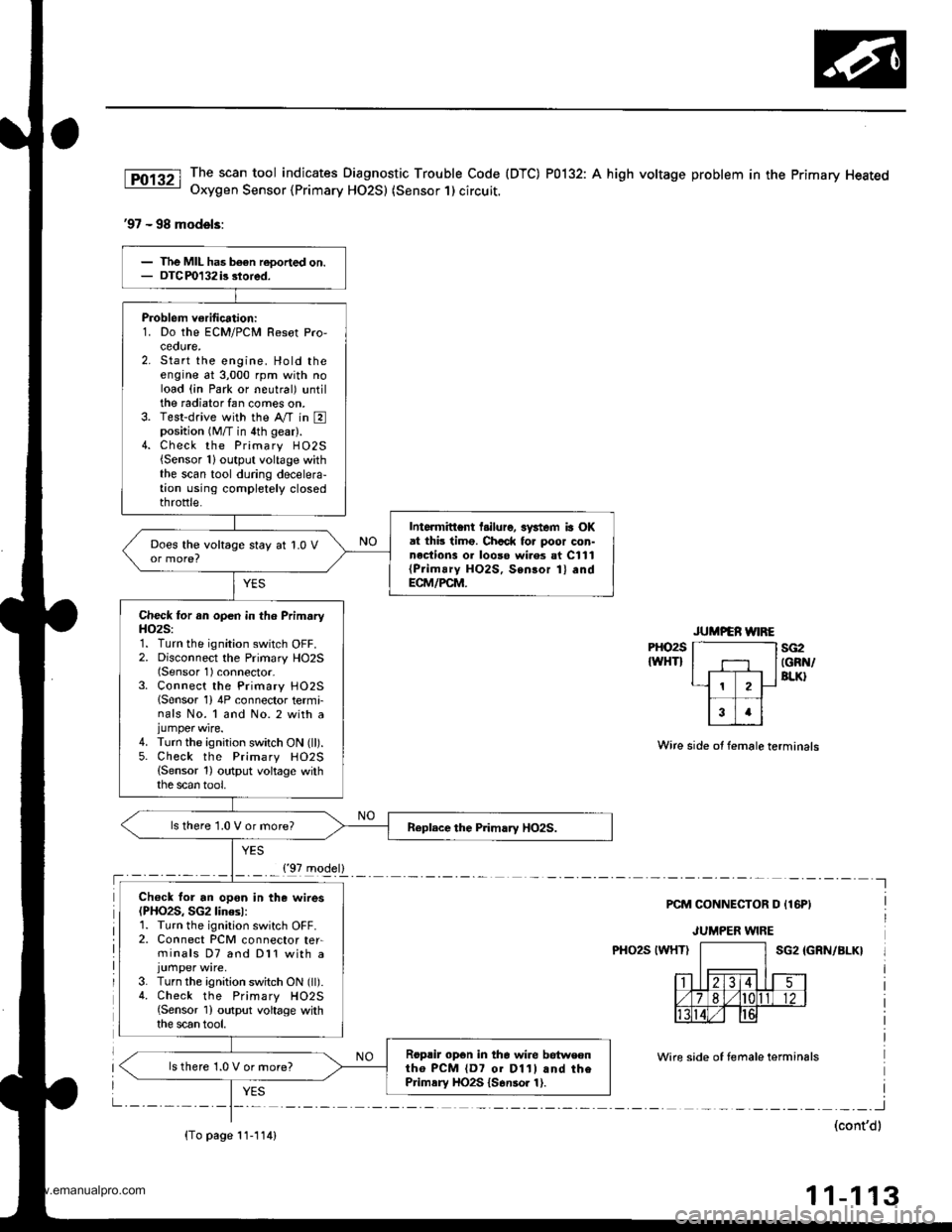
The scan tool indicates Diagnostic Trouble Code (DTC) P0132: A high voltage problem in the Primary HeatedOxygen Sensor {Primary HO2S) (Sensor 1) circuit.
'97 - 98 models:
PHO2S
IWHTIsG2IGRN/BLK}
Wire side ot female terminals
PCM CONNECTOR D {16PI
JUMPER WIRE
PHO2S IWHTISG2 IGRN/BLK}
Wire side of temale terminals
I
(cont'dl
11-113
Problem verification:1. Do the ECM/PCM Resot Pro,ceoute,2. Start the engine. Hold theengine at 3,000 rpm with noload (in Park or neutral) untilthe radiator fan comes on.3. Test-drive with the Ay'T in Eposition (M/T in 4th gear).4. Check the Primary H02S{Sensor 1}output voltage withthe scan tool during decelera-tion using completely closedthrottle.
Intormittent l.ilure, 3ystem ia OKat thb timo. Chcck fo. poor con-nections 01 looso wi.es at C111{Prim!ry HO2S, Sensor 1} andECM/PCM.
Does the voltage stay at 1.0 V
Check for an open in th6 PrimaryH()2S:1. Turn the ignition switch OFF.2. Disconnect the Primary HO2S(Sensor 1) connector-3. Connect the Primary HO25lSensor 1) 4P connector termi-nals No. 1 and No. 2 with ajumper wire.4. Turn the ignition switch ON (ll).5. Check the Primary HO2S(Sensor 1) output voltage withthe scan tool,
ls there 1.0 V or more?
Ch€ck for an opon in the wires(PHO2S, SG2linesl:1. Turn the ignition switch OFF.2. Connect PCM connector ter-minals D7 and Dl1 with a
3. Turn the ignition switch ON (ll).4. Check the Primary HO2S{Sensor 1) output voltage withthe scan tool.
Roprir opon in the wire betweontho PCM {D7 01 D11l and thePrimsry HO2S {S6nsor 1).
ls there 1.0 V or more?
{'97 model}
{To page 11-114)
www.emanualpro.com
Page 339 of 1395

Barometric Pressure (BARO) Sensor
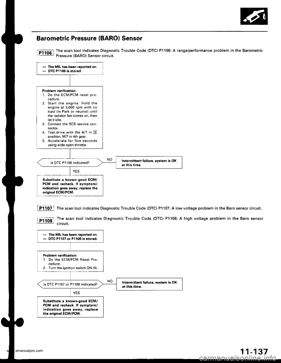
The scan tool indicates Diagnostic Trouble Code (DTC) P1106: A range/performsnce problem in the Barometric
Pressure {BARO) Sensor circuit.
The MIL has been reDorted on.OTC Pl106 b slored.
Problem ve.ification:1. Oo the ECM/PCM reset pro'
ceoure.2. Start the engine. Hold theengine at 3,000 rpm with noload (;n Park or neutral) untilthe radiator lan comes on, thenlet it idle.3. Connect the SCS service con-nector,4. Test'drive with the A/T in Eposition, M/T in 4th gear.
5. Accelerate Ior five secondsusing wide open throttle.
Intermittent fsilure, sy3tom i5 OKat this time.ls DTC P1106 indicated?
Substitute a known-good ECM/PCM .nd recheck. It symptom/indication goes away, replace theorigioal ECM/PCM.
fTiloz l
tP11o8l
The scan tool indicates Diagnostic Trouble Code (DTC) P1107: A low
The scan tool indicates Diagnostic Trouble Code (DTC) Pl108: A
circuit.
voltage problem in the Baro sensor circuit.
high voltage problem in the Baro sensor
- The MIL h.3 b€en roport€d on.- OTC Pl10? or Pl108 i3 stored.
Problom veritic.lion:L Do the ECM/PCM Reset Pro-cedure.2. Turn the ignition switch ON (lli.
Intarmittoni failure, lystom b OKat thb time.ls DTC P1107 or P1108 indicated?
Sub3tituto a known-good ECM/PCM and rcch6ck. ll symptom/indication 9oo3 away. .oplacorho o.igin.l ECM/PCM.
www.emanualpro.com
Page 352 of 1395

ldle Control System
ldle Control System
I P0505 | The scan tool indicates Diagnostic T.ouble Code (DTCI PO5O5: ldlecontrol svstem mattunction.
NOTE: lf DTC P1508 is stored at the same time as DTC P0505, troubleshoot DTC P1508 first. then troubleshoot DTC p0505.
Possibls Cause
. IAC valve mechanical malfunction. Throttle body clogged port, improper adlustment. Intake manifold gasket leakaging. Intake air hose loose leakaging. Vacuum hose leakaging
a ECT sensor incorrect output. Throttle Position sensor incorrect output
Troubleshooting Flowchart
The MIL has been reDorted on.DTC P0505 is sto.ed.
Problem verificationi1. Start the engine. Hold theengine at 3,000 rpm with noload (in Park or neutral) untilthe radiator Ian comes on, thenlet it idle.2. With the scan tool, check thelollowing items.- Throttle position should beapprox. 10% with the throt-tle {ully closed.- Engine coolant temperature shorJld be 194 - 205'F(90 - 96"C).lf they are not within thespec., repair the faulty sen-sor circuit.3 Check the engine speed atidle with no-load conditions:headlights, blower fan. reardefogger, radiator lan, and airconditioner are not operaling,
Inte.mittent failure. syltem is OKat this time.ls it 750 {730)* i 50 rpm?
ls il 700 (680)' rpm or less?
{To page 11-151)(To page 1'l-151)
l:'99 - 00 models
www.emanualpro.com
Page 532 of 1395
Description
PCM
PGM.FIControl System
Throttle Position SensorSignelVehicle Speed SensorSignal
Engin€ Coolsnt TomperatureSen30r SignalService Ch€ck Connectol
A/T Control Svstem
INTERLOCK
Shift Control
Shift ConlrolSolenoid Valve ACONTROL UNITr
RShift ControlSolenoid Valve B
N
Linear SolenoidD
Lock-up Control
2
Lock-up ControlSolenoid valve A1
Lock-up ControlSolenoid Valve BOver-DriveSwitch Signal
Mainshaft Speed SensorSignalE Indicator Light
Countershaft SpeedSensor SigntlSelt-Oiagnosis SigndSelf-DiagnosisFunc{ion
O/D OFFIndicetor Light
Electronic Gontrol System (cont'd)
'99 - 00 Models
14-16
www.emanualpro.com