Page 425 of 1395

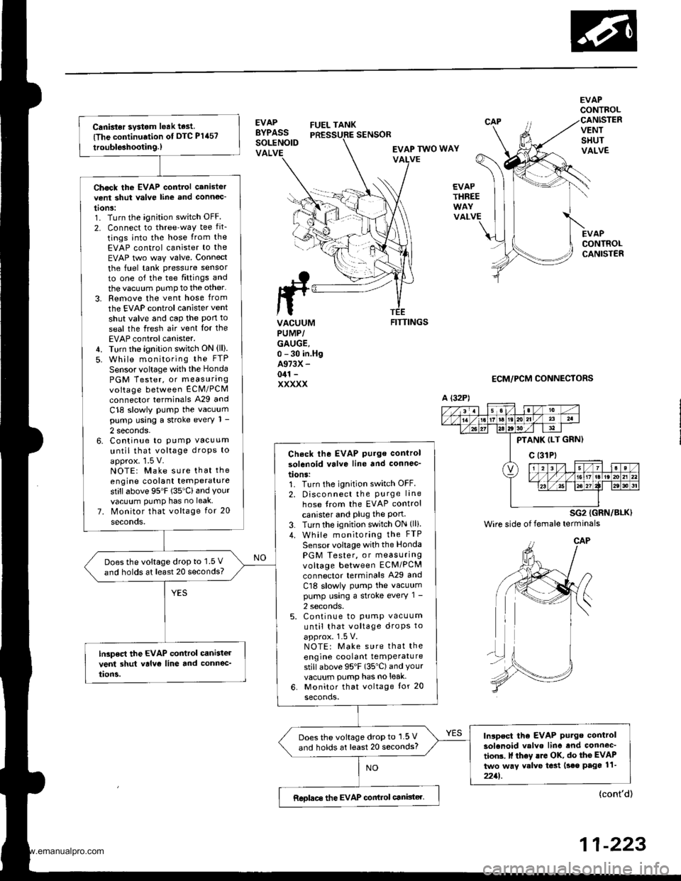
Canbter system leak test
{The continuation of DTC P1457
trouble3hootin9.)
Chock the EVAP control canistervent shut valve line and connoc'
tonS:1. Turn the ignition switch OFF
2. Connect to three'way tee fit_
tings into the hose from the
EVAP control canister to the
EVAP two way valve. Connect
the fuel tank pressure sensor
to one of the tee fittings and
the vacuum PumP to the other'
3. Remove the vent hose from
the EVAP control canister vent
shut valve and cap the Pon to
seal the fresh air vent Ior the
EVAP control canister.4. Turn the ignition switch ON (ll).
5. While monitoring the FTP
Sensor voltage with the Honda
PGM Tester, or measurangvoltage between ECM/PCM
connector terminals A29 and
C18 slowly PumP the vacuumpump using a stroke every 1 -
2 seconds.6. Continue to PumP vacuum
until that voltage droPs to
approx. 1.5 V.NOTE: Make sure that the
engine coolant temPeraturestillabove 95'F (35'Cland Yourvacuum PumP has no leak
7. Monitor that voltage for 20
seconds.
Check the EVAP Pu.ge control
solenoid valve line and connec-
tions:1. Turn the ignition switch OFF.
2. Disconnect the Purge lane
hose from the EVAP control
canister and Plug the Port3. Turn the ignition switch ON (lli.
4. While monitoring the FTP
Sensor voltage with the Honda
PGM Tester, or measuringvoltage between ECM/PCM
connector terminals A29 and
Cl8 slowly PumP the vacuumpump using a stroke every 1 -
2 seconds.5. Continue to pump vacuum
until that voltage droPs to
approx. 1-5 V.NOTE: Make sure that the
engine coolant temPeraturestill above 95'F (35"C) and Yourvacuum pump has no leak-
6. Monitor that voltage tor 20
seconds.
Doesthe voltage drop to 1.5 V
and holds at least 20 seconds?
lGp€ct the EVAP control cani3tel
vent 3hut valvo line and connec_
tion5.
Inlpect tho EVAP Putge control
solenoid valvo line and connec'
tion3. It th6y lro OK, do the EVAP
two way valve te3t (seo page 11-
2211.
Does the voltage drop to 1.5 V
and holds at least 20 seconds?
Reolace the EVAP conirol canister.
EVAPBYPASSSOLENOIDVALVE
FUEL TANK
EVAPCONTROL
VENTSHUTVALVE
EVAPCONTROLCANISTER
SENSOR
EVAP TWO WAYVALVE
EVAPTHREE
VALVE
ttrrL
ta
VACUUMPUMP/GAUGE,0 - 30 in.HgA973X -
041 -
XXXXX
FITTINGS
ECM/PCM CONNECTORS
A {32P)
PTANK ILT GRN)
c (31Pt
SG2 {GRN/BLK)
Wire side of female terminals
{cont'd)
11-223
www.emanualpro.com
Page 534 of 1395
Description
Electronic Control System (cont'dl
Grade Logic Control System
How it works:
The PCM compares actual driving conditions with memorized driving conditions, based on the input from the vehicle speed
sensor, the throttle position sensor, the barometric pressure sensor ('98 model). the engine coolant temperature sensor, the
brake switch signal, and the shift lever position signal, to control shifting while the vehicle is ascending or descending a
slope, or reducing speed.
SIGNALS DETECTED
Driving Rcsisl.nce
Judgemont ot Controlling Aroa
. Normal Modo {Flrt ro.d mode}. Ascending Mode. Deacending Mode. Deceleration Mode
14-14
www.emanualpro.com
Page 779 of 1395

26. Connect the vehicle speed sensor (VSS). the coun-
tershaft speed sensor. and the A,/T gear position
switch connectors,
VEHICLE SPEEO
SPEED SENSOACO'{NECTOR
Connect the lock-up control solenoid valve connec-
tor, then install the harness clamp on the clamp
bracket.
HARNESS CI-AMP
27.
RADIATOR HOSECLAMP
TRANSMISSIONGROUND CAB1ITERMINAL
LOCK-UP OONTROLSOLENOID VALVECONNECTOR
6x1.0mm12 N'm (1.2 kgi.m,8.? tbtftl
28.
29.
Instail the transmission ground cable terminal on
the transmission hanger, and install the radiator
hose clamp on the transmission hanger,
Connect the starter cables to the starter, and install
the harness clamD on the clamD bracket. Make sure
the crimped side of the starter cable ring terminal is
facing out.
STARTEBCABLE
STARTER CAAtf,
Install the air cleaner housing assembly and the
intake air duct.
Refill the transmission with ATF (see page 14-161).
Connect the battery positive terminal and negative
terminal.
Set the parking brake, Start the engine, and shift the
transmission through all gears three times.
Check the shift cable adjustment (see page 14-271]-.
Check the tront wheel alignment and adjust it if
needed (see section 18).
Let the engine reach normal operating temperature
(the radiator fan comes on) with the transmission in
E or N position, then turn it off and check the ATF
level {see page 14-160).
Perform a road test (see page 14-157 and 14-158).
30.
31.
34.
CLAMP BRACKET
37.
14-263
www.emanualpro.com
Page 1096 of 1395
Component Location
Index (cont'dl
SRS components are located in this area. Review the SRS component locations, precautions, and procedures in the SRS
section (24) before performing repairs or service.
BECIRCULATION CONTROL MOTOR4P CONNECTOR
EVAPORATOR TEMPERATURE SENSORTesl, page 22-44POWER TRANSISTOR3P CONNECTOR
AIR MIX CONTROL MOTORReplacement, page 22-43lest, page 22-13
BLOWER MOTOB2P CONNECTOR
BLOWER MOTOR HIGH RELAYTest, page 22-45
HEATER SUB.HARNESS
7P CONNECTOR
DASHBOARD WIRE HARNESS
HEATER CONTROL PANEL8P AND 2OP CONNECYORS
22-6
www.emanualpro.com
Page 1099 of 1395
cnNj@_snN
GRY
PNK/BLK
NED/8LU
REO/YEL
YEL/BLU
8RN/WHT
GRNI/VHT
GRN/RED
POWERTRANSISTOR
c401c402
22-9
4
ORNMHT
Fg"{
EVAPONATORTEMPERATURE SENSOR
fi3'.Hfi|$l#i9D>
"'"-
DASH LTGHTS _/4EE|GHTNESS < l_ REDCONTROLLER -!
REAR
fllf$!S,* (l aLurrLRELAY
O:8P coNNEcToR
n :20P c0NN€CToR
YEL/RED
GRN/YEL
8LU/8LK
BRN
YEL
s5v s coM
AMD P AIR MIXCONTROLMOTOB
HOT
VENT
B/LI/lODEH CONT8OLl
10T0RH/D MDEF
HEATER CONTROL PANEI-
8LK
www.emanualpro.com
Page 1101 of 1395

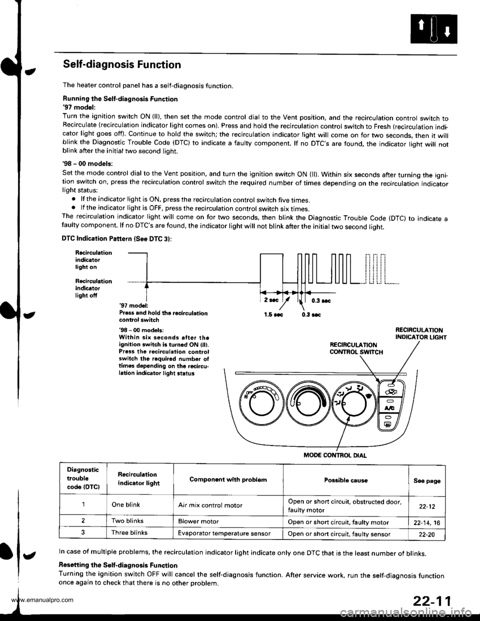
Self-diagnosis Function
The heater control panel has a self-diagnosis function.
Running the Self-diagnosis Function'97 mod€l:
Turn the ignition switch ON {ll), then set the mode control dial to the Vent position, and the recirculation controt switch toRecirculate {recirculation indicator light comes on). Press and hold the recirculation control switch to Fresh (recirculation indi-cator light goes off). Continue to hold the switch; the recirculation indicator light will come on for two seconds. then it willblink the Diagnostic Trouble Code (DTC) to indicate a iaulty component. lf no DTC'S are found, the indicator liqht will notblink atter the initial two second light.
'98 - 00 models:
Set the mode control dial to the Vent position, and turn the ignition switch ON (ll). Within six seconds after turning the igni-tion switch on, press the recirculation control switch the required number of times depending on the recirculation indicatorlight status:
.lftheindicatorlightisON,presstherecirculationcontrol switch five times..lftheindicatorlightisOFF,presstherecirculationcontrol switch six I|mes.The recirculation indicator light will come on for two seconds, then blink the Diagnostic Trouble Code (DTC) to indicate afaulty component. lf no DTC'S are found, the indicator light will not blink after the initial two second liqht.
DTC Indicaiion Pattern {See DTC 3}:
Rocirculationindicatorlight on
Recirculrtionindicatorlighi off'97 model:P.ess and hold th6 recircul.tioncontrol switch'98 - 00 modek:Within six second3 atter theignition switch b turned ON (lll.Prass the rocirculation controlswitch the required number oltimes depending on the r6circu-lation indicator light striu3
,r*
/1.5 aaa 0.3 aac
RECIRCULANONINDICATOR LIGHT
In case of multiple problems, the recirculation indicator light indicate only one DTC that is the least number of blinks.
Resetiing the Solf.diagnosis Funqtion
Turning the ignition switch OFF will cancel the self-diagnosis function. After service work, run the self-diaqnosis functiononce again to check that there is no other Droblem.
MODE CONTROL OIAL
Diagnostic
trouble
code {DTCI
R6circulation
indicator lightComponent with problsmPossiblo causcSee page
'lOne blinkAir mix control molorOpen or short circuit, obstructed door,
faulty motor22-12
2Two blinksElower motorOpen or short circuit, faultv motor22-14,16
Three blinksEvaporator temperature sensorOpon or short circuit, faulty sensor22-20
t
www.emanualpro.com
Page 1110 of 1395

Troubleshooting
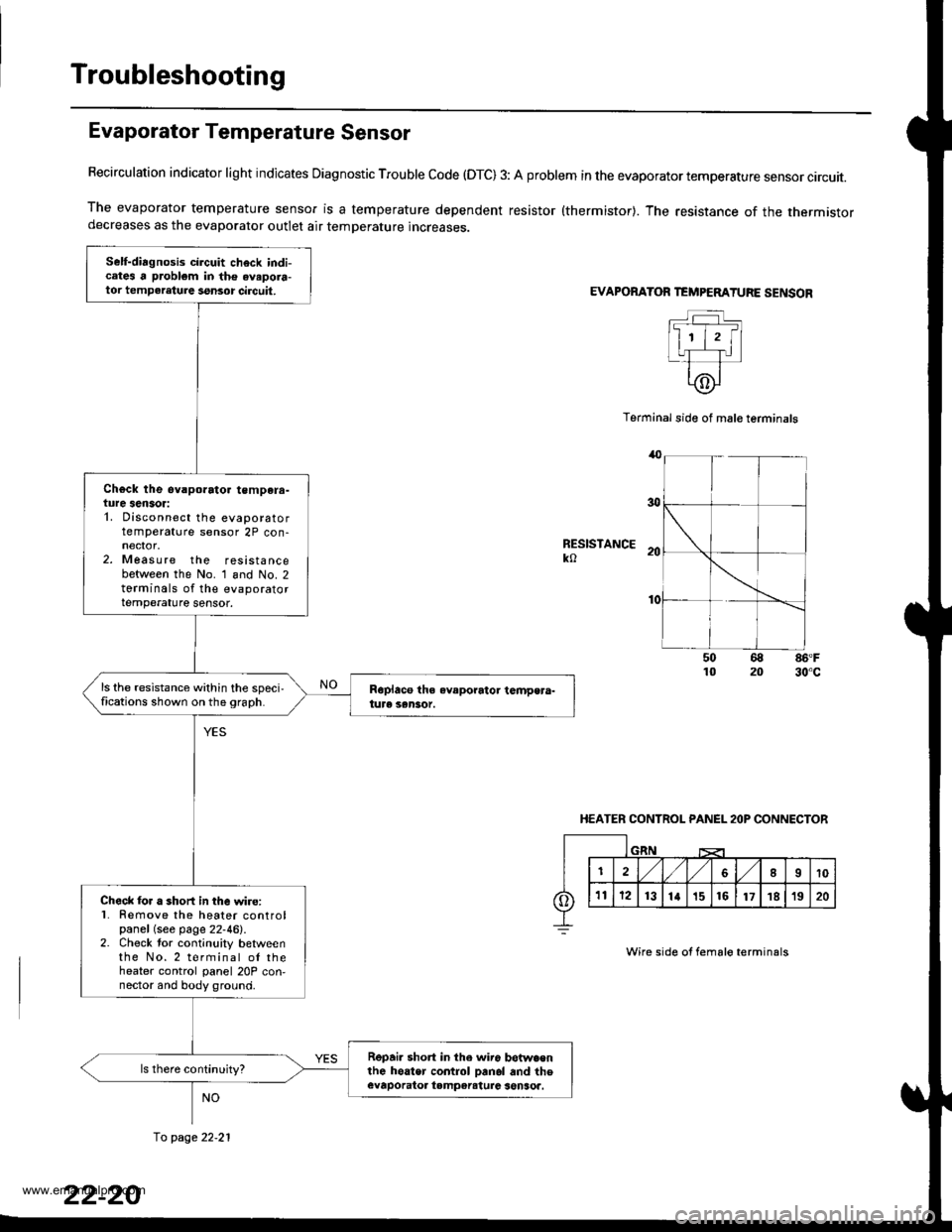
Evaporator Temperature Sensor
Recirculation indicator light indicates Diagnostic Trouble code (OTC) 3: A problem in the evaporator temperature sensor circuit.
The evaporator temperature sensor is a temperature dependent resistor {thermistor}. The resistance of the thermistordecreases as the evaporator outlet air temperature increases.
EVAPORATOR TEMPEMTURE SENSOR
Terminal side of mal€ terminals
RESISTANCEko
86'F30"c
HEATER CONTROL PANEL 2OP CONNECTOR
Wire side of fema16 terminals
Self-diagnosis circuit check indicates a problem in the avapora-tor tempeleture ssnsor circuit,
Ch€ck the ev.porato. tempera-ture sensor:1. Disconnect the evaporatortemperature sensor 2P con-
2. Measure the resistancebetween the No. 1 and No. 2torminals of the evaporatortemperature sensor.
ls the resistance within the speci,fications shown on the 9raph.
Check lor a short in the wire:l� Remove the heater controlpanel (see page 22-46).2. Check tor continuity betweenthe No.2 terminal ol theheater control panel 20P con,nector and body ground.
Repai. short in the wir6 betwa€nlhe hoater control Danol and theevaporatoa tampereturc senSoa.
fo page 22.21
www.emanualpro.com
Page 1111 of 1395

From page 22-20
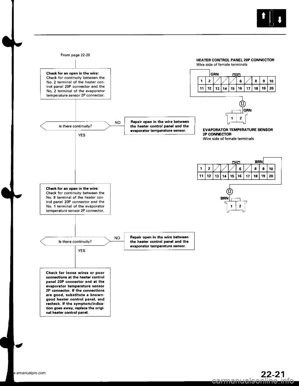
Chock tor an oDen in th€ wire:Check for continuity betlveen theNo. 2 terminal of the heater con-trol oanel 20P connector and theNo.2 terminal oI the evaporatortemperature sensor 2P connoctor.
Fopair open in the wiro betweentho heato. control penel and theevaporator tempetatule sensor.
Check for rn opsn in tha wiJe:Check for continuity between theNo. 9 terminal of the heater control oanel 20P connector and theNo. 'l terminal ot the evaporatortemperature sensor 2P connector,
Ropair open in tho wire betwegnthe heater control oanel and theevaporator tgmpcrature sen3or.
Chgck fol loose wiros or pool
connectrons at the hoator controloan6l 20P connector and at theeveporator temperatura Sensol2P connector. It the connectionsare good, substitute a known-good he.tel contlol panel, andrech€ck. ll thg symptom/indica-tion 90o3 rwey, roplsce the origi-nal heater control oanel.
HEATER CONTROL PANEL 2OP CONNECTORWire side ol female terminals
EVAPORATOB TEMPERATURE SENSOR2P CONNECTORWire side oI temale terminals
1810
1112131a1516't7181920
GIIN
12,/ l,/689t0
'tl1213lat1516'1718't920
o
+
li-L:t
www.emanualpro.com