Page 132 of 1395

13. Remove the upper radiator hose, heater hose and
water bypass hose.
WATER BYPASS
UPPEBRADIATORHOSE
17
HEATERHOSE
Remove the engine wire harness connectors and
wire harness clamps from the cylinder head and the
intake manifold.
o Four fuel injector connectors
. Engine coolant temperature (ECT) sensor con-
neclor
. Radiator fan switch connector
. Coolant temperature gauge sendlng unlt connec-
tor
. Throttle position sensor connector
. Manifold absolute pressure {MAP) sensor con-
nector
Primary heated oxygen sensor (primary HO2S)
connector
ldle air control (lAC) valve connector
Distributor connector
Remove the spark plug caps and distributor from the
cylinder head.
Remove the cruise control actuator (see section 4).
Support the engine with a jack, then remove the
upper bracket. Make sure to place a cushion
between the oil pan and the iack (see page 6-10).
a
18. Remove the cylinder head cover.
19. Inspect the timing belt (see page 6-9).
CYLINDER
(cont'd)
6-19
www.emanualpro.com
Page 145 of 1395

Cylinder Head
Installation (cont'dl
'13. Align the marks on the cylinder head plug to thecylinder head upper surface, then install the cylin
der head plug in the end of the cylinder head.
CYLINOER HEADPLUGReplace.
lnstallthe back cover.
To set the camshafts at TDC position for the No. lpiston, align the holes in the camshafts with theholes in the No. l camshaft holders and insert 5.0mm pin punches in the holes. Install the keys into
the camshaft grooves.
37 N m (3.8 *gl.m, 27 lbt.tr)
9.8 N.m (1.0 kgtm,7.2|hrftl
Push the camshaft pulleys onto the camshafts. thentighten the retaining bolts to the torque specified.
6-32
14.
KEYS
I x 1.25 mm
6x1.0mm
Install the timing belt (see page 6-1 1).
Adjust the valve clearance (see page 6-3).
Thoroughly clean the head cover gasket and thegroove.
lnstall the head cover gasket in the groove of thecylinder head cover. Seat the head cover gasket in
the recesses for the camshaft first, then work it into
the groove around the outside edges. Make sure thehead cover gasket is seated securely in the corners
of the recesses with no gap.
17.
'18.
19.
www.emanualpro.com
Page 174 of 1395

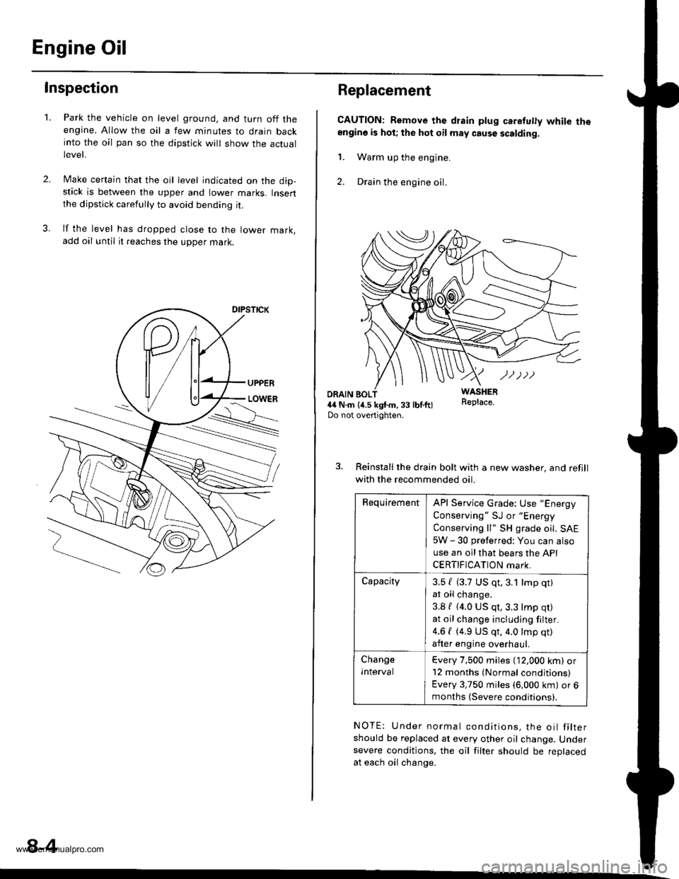
Engine Oil
Inspection
2.
1.Park the vehicle on level ground, and turn off theengine. Allow the oil a few minutes to drain backinto the oil pan so the dipstick will show the actuallevet,
Make certain that the oil level indicated on the dip-stick is between the upper and lower marks. Insertthe dipstick carefully to avoid bending it.
lf the level has dropped close to the lower mark,add oil until it reaches the upper mark.
8-4
Replacement
CAUTION: Remove the drain plug caretuly white theengino is hot; the hot oil may cause scalding.
1. Warm up the engine.
2. Drain the engine oil.
WASHERR€place.ORAIN BOL4il N.m {4.5 kgtm,33 lbf.ft)Do not overtighten.
3. Reinstall the drain bolt with a new washer, and refill
with the recommended oil.
RequirementAPI Service Grade: Use "Energy
Conserving " SJ or "Energy
Conserving ll" SH grade oil. SAE
5W - 30 preferred: You can also
use an oil that bears the API
CERTIFICATION mark.
Capacity3.5 { (3.7 US qt,3.1 lmp qt)
at oil change.
3.8 / (4.0 US qt,3.3 lmp qr)
at oil change including filter.
4.6 { (4.9 US qt, 4.0 lmp qt)
after engine overhaul.
Change
Inlerval
Every 7,500 miles (12,000 km) or12 months (Normal conditions)
Every 3,750 miles (6,000 km) or 6months (Severe conditions).
NOTE: Under normal conditions, the oil filtershould be replaced at every other oil change. Undersevere conditions, the oil filter should be replacedat each oil change.
www.emanualpro.com
Page 192 of 1395
Radiator
1.
2.
3.
4.
Replacement
CONDENSERFAN,/SHROUDASSEMBLY
Drain the engine coolant.
Remove the upper and lower radiator hoses, and
ATF cooler hoses.
Disconnect the fan motor connector.
Remove the radiator upper bracket, then pull up the
raotalor,
5. Remove the fan shroud assemblies and other parts
from the radiator.
6. lnstall the radiator in the reverse order of removal.
NOTE:
. Set the upper and lower cushions securely.
. Fill the radiator with engine cooiant and bleed the air.
RADIATOR CAP
RADIATOR
6x1.0mm9.8 N.m 11.0 kgf.m,7.2 tbl.trl
6x1.0mm7 N.m (0.? kgd.m, 5 lbl.ftl
UPPER MDIATOR HOSE
Reler to section 14when installing.
DRAIN PLUG
LOWER CUSHION
LOWERTOR HOSE
RADIATORASSEMBLY
6x1.0mm7 N.|n 10.7 kgt.m,5 tbt.ftl
rriItriiii
10-4
www.emanualpro.com
Page 193 of 1395
Engine Coolant Refilling and Bleeding
1. Slide the heater lemperature control lever to maxi
mum heat.
Make sure the engine and radiator are cooi to the
touch.
2. Remove the radiator caP.
3. Loosen the drain plug, and drain the coolant.
4. Remove the drain bolt from the cylinder block.
DRAIN PLUG
DRAIN BOLT78 N.m {8.0 ksl.m, 58 lbtft}
10-5
6.
7.
Apply liquid gasket to the drain bolt threads, then
reinstall the bolt with a new washer and tighten it
securely.
Tighten the radiator drain plug securely.
Remove, drain and reinstall the reservoir' Fill the
tank halfway to the MAX mark with water, then up
to the MAX mark with antitreeze.
(cont'd)
www.emanualpro.com
Page 329 of 1395
![HONDA CR-V 1999 RD1-RD3 / 1.G Workshop Manual
Misfire Detected in One Cylinder
Ipffi1] Thescantoot indicates Diagnostic Trouble Code (DTC) P0301: Cylinder 1 misfire detected.
lF03O2l 16".""n toot indicates Diagnostic Trouble Code (DTC) P0302; Cy HONDA CR-V 1999 RD1-RD3 / 1.G Workshop Manual
Misfire Detected in One Cylinder
Ipffi1] Thescantoot indicates Diagnostic Trouble Code (DTC) P0301: Cylinder 1 misfire detected.
lF03O2l 16".""n toot indicates Diagnostic Trouble Code (DTC) P0302; Cy](/manual-img/13/5778/w960_5778-328.png)
Misfire Detected in One Cylinder
Ipffi1] Thescantoot indicates Diagnostic Trouble Code (DTC) P0301: Cylinder 1 misfire detected.
lF03O2l 16".""n toot indicates Diagnostic Trouble Code (DTC) P0302; Cylinder 2 misfire detected.
I P0303 | fne scan tool indicates Diagnostic Trouble Code (DTC) P0303: Cylinder3 misfire detected.
lF0il04l 16" ""un tool indicates Diagnostic Trouble Code (DTC) PO3O4: Cylinder 4 misfire detected
Description
Misfire detection is accomplished by monitoring the crankshaft speed with the crankshaft speed fluctuation (CKF) sensor
which is attached to the crankshaft.
lf misiiring strong enough to damage the catalyst is detected, the MIL will blink during the time of its occurrence. and DTC
P0301, P0302, P0303 and/or P0304 will be stored. Then, after the misfire has ceased, the MIL will come on.
lf misfiring that increases emissions is detected during two consecutive driving cycles. the MIL will come on, and DTc
P0301, P0302, P0303 and/or P0304 will be stored.
NOTE: lJ some of the DTcs listed below are stored at the same time as a misfire DTc, troubleshoot those DTcs first, then
troubleshoot the misfire DTC.
P0107, P0108, P'n2a, P1129t MAP sensor
Po'17 'l , P0112t Fuel suPP|Y system
P0441: EVAP insufficient Purge flow
P1336, P1337: CKF sensor
P1359, Pl361, P1362: TDC sensor
Pl381, P1382: CYP sensor
Possible Cause
. Fuel injector clogging, fuel leakage, air leakage
. Fuel injector circuit open or shorted
. Spark plug carbon deposits, fouling, malfunction
. lgnition wires open, leaking
. Distributor malfunction
. Compression low
. Valve clearance out of specification
(cont'd)
11-127
www.emanualpro.com
Page 330 of 1395

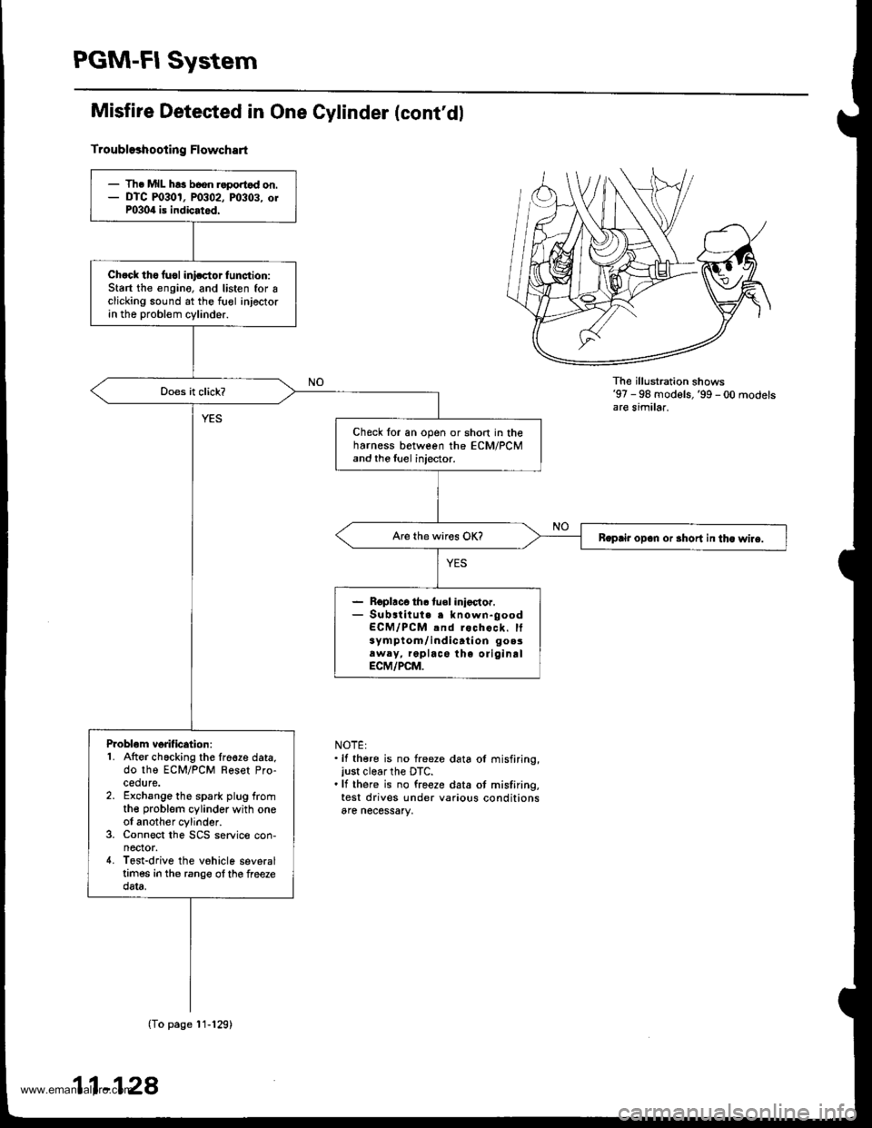
PGM-FI System
Misfire Detested in One Cylinder (cont'dl
Troubl93hooting Flowchart
The illu stration shows'97 - 98 models,'99 - 00 modelsare similar.
NOTE:.lf there is no freeze data ol misfiring,just clear the DTC..lf there is no freeze data ot misfiring,test drives under various conditionsare necessary,
- Th. MIL h!3 b6on r.portod on.- DTC m30r, P0302, m303. orP0304 is indicated.
Ch.ck tho fuol inicctor tunction:Start the engino, and listen for Iclicking sound at the fuol injectorin the probl€m cylinder.
Check for an open or short in theharness between the ECM/PCMand the luel injector.
Boprir opan or 3hort in tha wlre.
- Roplaco th. tuel inioctor.- Substitut. . known-goodECM/PCM .nd rochock. It3ym ptom/ indicati on go.3aw.y, replace the oliginalECM/PCM.
Problom vorification:1. Atter chacking the lre€ze data,do the ECM/PCM Reset Pro-cedure.2. Exchange the spark plug fromthe problem cylinder with oneol another cylinder.3. Connect the SCS service con-nector.4. Tost-drive the vohicle severaltimes in the rango ol the freezedata.
(To page'11-129)
11-128
www.emanualpro.com
Page 331 of 1395
(From page 11-128)
lntormittent misfire due lo sparkplug fouling, etc. (no mislire at
this tim€).
ls DTC P0301, P0302, P0303,or P0304 indicated?
ooes the misfire occur in theother cylinder?Replace the faulty spark Plug.
Check lor fuel iniector maltunc-
t|on:1. Exchange the fuel injectorfrom the problem cylinderwith one from another cylin-der.2. Let the engine idle for two min
utes.3. Test'drive the vehicle severaltimes in the range of the freezedata,
lntermittent misfiro due lo bad
contrct in the fuel iniector con-nector {no misfire at this time).
ls DTC P0301, P0302, P0303,or P0304 indicated?
Does the misfire occur in theother cylinder?Replace lhe faulty luel inlector.
Check following items- Valvo clearance- Cvlinder l€ak-down- Compression- Crsnkshaft Speed FluctuationICKF) sensol
NOTE: lf there is no freeze data of misfiring, test drives under various condi_
tions are necessary.
11-129
www.emanualpro.com