1999 HONDA CR-V Main relay
[x] Cancel search: Main relayPage 391 of 1395
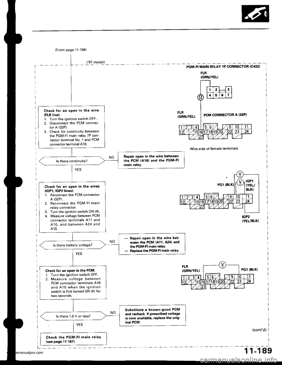
lFrom page 11 188)
Ch6ck lor an open in the wir€
{FLR line):1. Turn the ignition switch OFF.
2. Disconnect the PCM connec-
tor A (32P).
3. Check for continuity between
the PGM-FI main relay 7P con-
nector terminal No. 1 and PCM
connector terminal A16.
Repair open in the wire be{weonthe PCM lAl6l and the PGM-FImain relay.
Check for an open in the wir€s
{lGP1, lGP2lin€s):'1. Reconnect the PCM connectorA (32P).
2. Reconnect the PGM'Fl main
relay connector.3. Turn the ignition switch ON (lli.
4. Measure voltage between PCM
connector terminals A11 and
A10, and between A24 andA10.
- Repair open in the wir€ bet'
ween th€ PCM {A11, A2ia} end
the PGM-FI main relay.- Reolsce the PGM-FI main rolaY.
ls there battery voltage?
Check tor an open in the PCM:
1. Turn the ignition switch OFF.2, Measu re voltage betweenPCM connector terminals A16
and A10 when the ignition
switch is first turned ON {ll) for
Substitute a known-good PCM
and recheck. lf ptesctibed volttgeis now available, roplaco tho orig'in.lPCM.
ls there '1.0 V or less?
Check the PGM-Fl m.in.elaV(see page 11-187).
('97 model)
IGRN/YELI
-t
PGM.FI MAIN RELAY 7P CONNECTOR (C432I
FLR
Wire side of lemale terminals
IGP2(YEL/BLK)
(cont'd)
_l
1 1-1 89
www.emanualpro.com
Page 392 of 1395
Fuel Supply System
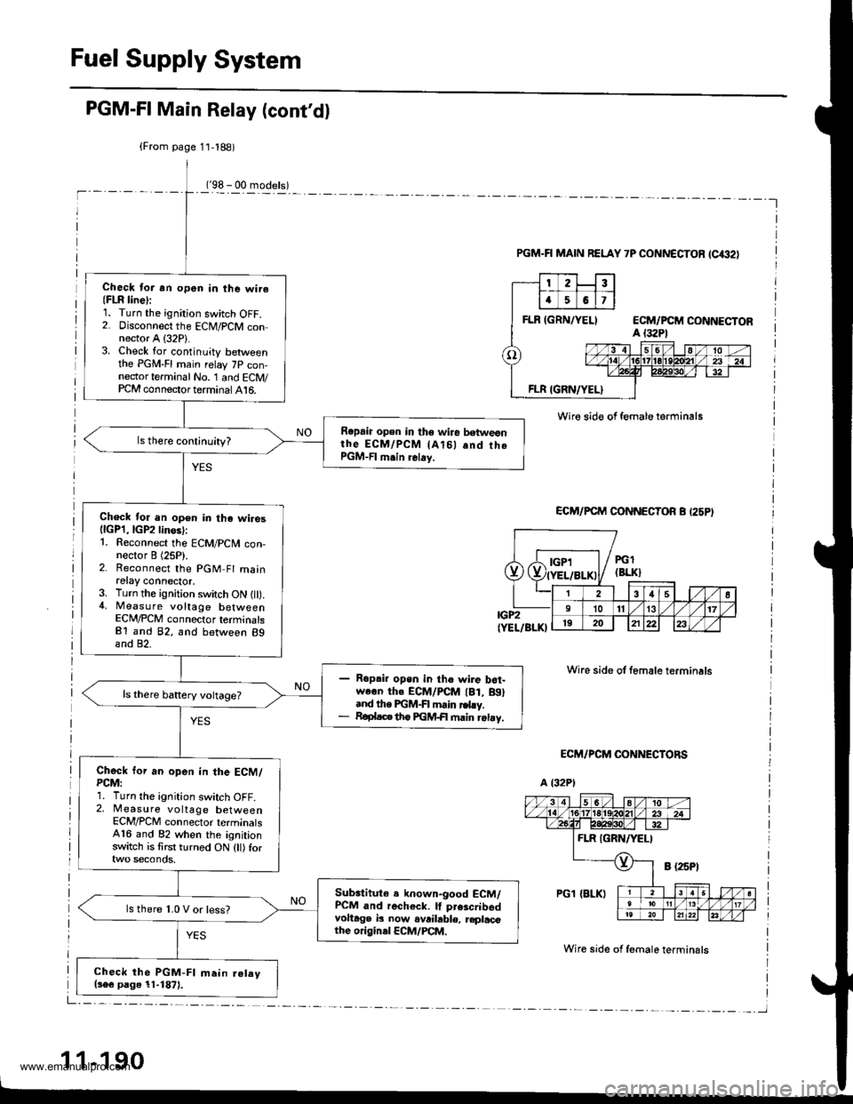
PGM-FI Main Relay (cont'dl
('98 - 00 models)-l
(From page 11,188)
Check lor an open in the wire(FLR line):1. Turn the ignition switch OFF.2. Disconnect the ECM/PCM connector A (32P1.3. Check for continuity betweenthe PGM-FI main relay 7P con-nector terminal No. '1 and ECM/PCM connector terminal 416.
Repaia open in the wire betweenthe EcM/PcM lAl5l .nd thePGM-FI m.in relay.
Check for an open in the wiresllcPl,lGP2linos):1. Reconnect the ECM/PCN4 con-nector I (25P).2. Reconnect the PGM Fl mainretay connector.3. Turn the ignition switch ON l).4, Measure voltage betweenECM/PCM connector terminalsB1 and 82, and between 89and 82.
Ropai. open in tho wire b6t-we€n th. ECM/PCM lBt, Btl.nd the FGM-FI main rd.y.R€plac€ th6 FGM+| main retay,
Chock for an open in the ECM/PCM:1. Turn the ignition switch OFF.2, Measure voltage betweenECM/PCM connector terminals416 and 82 when the ignitionswitch is first turned ON (tl) for
Subrtitute e known-good ECM/PCM and recheck. lf prescribsdvoltage b now ovrihble, replacothe originel ECM/PCM.
ls there 1.0 V or less?
Check the PGM-FI main.elav(s6e page 11-1871.
PGM.FI MAIN RELAY 7P CONNECTOF (C€2)
Wire sid€ of female terminals
ECM/PCM CONNECTOR B I25PI
IGP2(YEL/BLKI
ECM/PCM CONNECTORS
a t32Pl
Wire side of female terminals
Wire side of f€male terminsls
1 1-190
Dde"Jt;;liL-F-T--
PGl(BLK}
38s l1011131719202122
www.emanualpro.com
Page 395 of 1395
Intake Air System
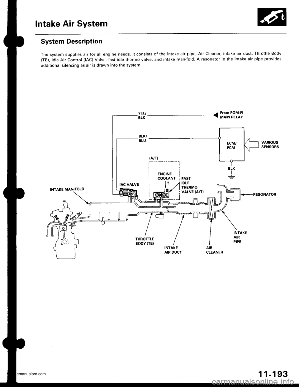
System Description
The system supplies air for all engine needs. lt consists of the intake air pipe, Air Cleaner, intake air duct, Throttle Body
(TB), ldle Air Control (lAC) Valve, fast idle thermo valve, and intake manifold. A resonator in the intake air pipe provides
additional silencing as air is drawn into the system.
INTAKE MANIFOLD
YEL| - - Fiom PGM'FI
BLK T MAIN RELAY
IDLETHERMO
lJ- _iuo'u'j"'
INTAKEAIR DUCT
vaRtousSENSORS
FESONATON
THROTTLEBODY (TB)
1 1-193
www.emanualpro.com
Page 570 of 1395

PCM Terminal Voltage/Measuring Conditions
A/T Control System -'98 - 00 Models
The PCM terminal voltage and measuring conditions are shown for the connector terminals that are related to the A"/T con-
trol system. The other PCM terminal voltage and measuring conditions are described in section 11.
FCM Connector Terminal Localions
NOTE: 819 and C3 terminalsare applied to'99 - 00 models.
o (16Pt
T6rminal NumberSignalDescriptionMeasuring Conditions/Terminal Voltage
A5CRSDownshift signal input from
cruise control unit
When cruise control is used; Pulsing signal
A10scsTiming and adjustment service
check signal (5 V from PCM)
With ignition switch ON (ll) and service check
connector open:5 V
With ignition switch ON (ll) and service check
connector jumped with special tool: 0 V
A14('98 model)
D4 INDD4 indicator light control
{Voltage from PCM turns D4 light
oN)
When ignition switch is first turned ON (ll):
Battery voltage for two seconds
In E position: Battery voltage
A14
('99 - 00 models)
D INDD indicator light control(Voltage from PCM turns D light
oN)
When ignition switch is first turned ON (ll):
Baftery voltage for two seconds
ln E position: Battery voltage
428ILUInterlock control(Voltage from PCM)
When ignition switch ON {ll), brake pedal
depressed, and accelerator pedal released:
Battery voltage
A.32STOP SWBrake switch signal inputBrake pedal pressed; Battery voltage
Brake pedal released: 0 V
FCM CONNECTOR B I25P}
Terminal NumberSignalDescriptionMeasuring Conditions/Terminal Voltage
B1IGPlPower supply circuit from main
relay via under-hood Fuse 44
With ignition switch ON {ll): Battery voltage
With ignition switch OFF: 0 V
82PG1Ground (G101)
B8LSMLinear solenoid power supply
negative electrode
IG P2Power supply circuit from main
relay
With ignition switch ON (ll): Baftery voltage
With ignition switch OFF: 0 V
810PG2Ground (G101)
B17Linear solenoid power supply
positive electrode
With ignition switch ON (ll): Pulsing signal
819
('99 - 00 models)
O/D INDOver-Drive (O/D) OFF indicator
light control
When ignition switch is first turned ON (ll):
0 V for two seconds
O/D OFF indicator light ON:0 V
O/D OFF indicator light OFF: Battery voltage
s20Ground (G101)
B�21VBUBack-up power supply(under-hood Fuse 47)
Always battery voltage
B�22LG2Ground (G101)
14-54
www.emanualpro.com
Page 639 of 1395
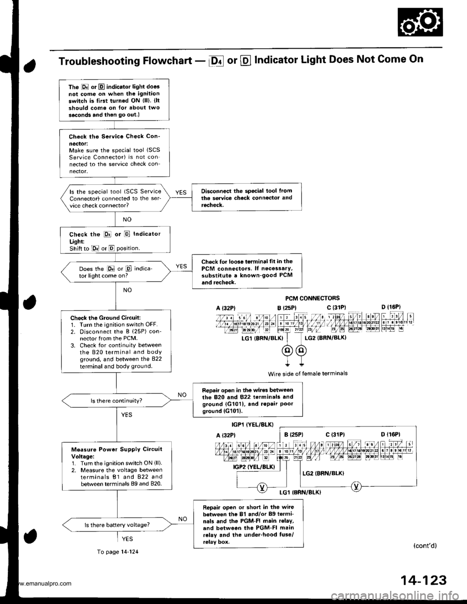
Troubleshooting Flowchart - Df or @ Indicator Light Does Not Come On
PCM CONNECTORS
B t2sPl c (31D (16P)
l*f4tr 8-
f - -- -6 3 rol ,: irr t lrpri$fe?0?r/a)1 e 'oI 13 11/ / l//|rrr I , ltelx ?r2? r,/i-T_LG1 {8RN/BI-KI I LG2 (BRN/BL()I
@@I++
Wire side of lemale terminals
(cont'd)
14-123
The E or El indicator light doe3not cofie on when the ignitaon
switch is first turned ON {ll). {ltshould como on for about two
s.cond3 and ihen go out.l
Check ths Service Check Con-
neclor:Make sure the special tool (SCS
Service Connector) is not connected to the service check connector.
Disconnecl the special lool lromtha service check connoctor andrecheck.
ls the special tool (SCS ServiceConnector) connected to the ser_vice check connector?
check the E or E Indicator
Ught:Shift to E or E position.
Check for loo3e t6lminal tit in thePCM connectors. lf necessary.substitute a known-good PCMand recheck.
Does the E or P indica-tor light come on?
Check the Gtound Circuil:1. Turn the ignition switch OFF.2. Disconnect the B (25P) con-nector from the PCM.3. Check for continuitY betweenthe 820 terminal and bodyground, and between the 822
terminal and body ground.
Repair open in the wires betweenthe 820 and 822 terminals andground {G1011, and r€Pair Poorground (G101).
ls there continuity?
Measure Power Supply CircuitVoltage:1. Turn the ignition switch ON 1ll).2. Measure the voltage betweenterminals B1 and 822 andbetween terminals Bg and 820.
Repair open or short in tho wi.ebetween the 81 and/or Bg tormi-nals and the PGM-FI main r€lay,.nd between tho PGM-FI mainrelay and the under-hood tuse/relay box.
ls there battery voltage?
A l32Plc (31P)
c (31P)
YES
To page 14-124
www.emanualpro.com
Page 948 of 1395

Anti-lock Brake System (ABSI,'97 - 00 Models
Special Tools ............. 19-26
Component Locations ......................... 19-27
Anti-lock Brake System (ABS)
Features/Construction ............. ......, 19-2A
Circuit Diagram ......... 19-32
ABS Control Unit Terminal
Arrangement ......... 19-34
Troubleshooting Precautions ............. 19-36
Diagnostic Trouble Gode (DTC)
Diagnostic Trouble Code (DTC)
Indication (SCS Model ................ 19-38
DTG Erasure (MES Mode) ............... 19-39
Troubleshooting lndex .................... 19-40
Troubleshooting
ABS Indicator Light Does Not
Come On ............ 19-41
ABS Indicator Light Does Not
Go Off (No DTC) ........................... 19-43
DTC 1r - 18:
Wheel Sensor .... 19-45
DTC 31 - 38:
Solenoid ............. 19-47
DTC 51 - 53:
ABS Pump Motor ......................... 19-49
DTC 54:
Main Relay ......... 19-52
DTC 61:
lgnition Voltage ........................... 19-54
DTC 81:
Central Processing Unit (CPU) .... 19-55
Modulator Unit
Removal/lnstallation ....................... 19-56
ABS Control Unit
Replacement ..,...... 19-57
Pulsers/Wheel Sensors
Inspection .............. 19-57
Wheel Sensor Replacement ............ 19-58
www.emanualpro.com
Page 959 of 1395

Troubleshooting Precautions
ABS lndicalor
1 lf the system is oK, the ABS indicator goes off two seconds after turning the ignition switch oN 1l) wathout staningthe engine, and then comes on again and goes off after two seconds. This occurs because the ABS control unit isturned on by the lG2 power source.2. The ABS indicator comes on when the ABS control unit detects a problem in the system. However, even thouoh thesystem is operating properly, the ABs indicator will come on too, under the following conditions:. Signal disturbance
. Wheel spin
. Only drive wheels rotate. Battery voltage fluctuates
To determine the actual cause of the problem, question the customer about the problem, taking these conditions intoconsideration:
3 When a problem is detected and the ABS indicator comes on, the indicator can stay on until the ignition switch isturned OFF, or it can automatically go off, depending on the mode.. Indicator stays on untilthe ignition switch is turned off: When the system is in the system down mode.. Indicator automatically goes off: When the system is in the control inhibition mode.4 The ABS indicator stays on when the system is reactivated without erasing the DTC, but it goes off after starting thevehicle.
When the wheel sensor system is faulty and the ABS indicator comes on. the algorithm of the system automatically turnsoff the ABS indicator after the wheel speed signal returns to the normal speed. Also, when the DTc is erased, the cpu isreset and the ABS indicator goes off when the system checked out normal by the initial diagnosis.Therefore, test-drive the vehicle after servicing the wheel sensor system. and be sure that the ABS indicator does notcome on.
5 When the ABS control unit outputs battery voltage to the gauge assembly, the ABS indicator ooes off.
Diagnostic Trouble Code (DTCI
1. The diagnostic trouble code (DTc) is memorized when a problem is detected and the ABS indicator does not go off,or when the ABS indicator comes on.The DTc is not memorized when the ABS indicator comes on unress the cpu is activated,2 The memory can hold any number of DTCs. However, when the same DTc is detected twice or more, the tater one iswritten over the old one.
Therefore, when the same problem is detected repeatedly, it is recorded as one DTC.3. The DTCs are indicated in the order of ascending number, not in the order they occur.4. The DTCS are memorized in the EEPROM (non-volatile memorv).Therefore, the memorized DTcs cannot be canceled by disconnecting the battery. perform the specified procedures toerase the DTCS.
Self-diagnosis
1. Self-diagnosis can be classified into these four categories:' Initial diagnosis: Performed right after the eng ine starts and untir theABS indicator goes off.. Except ABS control: Performed when the ABS is not functioning.. During ABS control: Performed when the ABS is functioning.. During warning: Performed when the ABS indicator is ON.2. The system performs the fo|owing contrors when a probrem is detected by the serf-diagnosis:. ABS indicator ON. Memorv of DTC. Mode changetothe "system down mode,, or the ,,control inhibition mode,,.
MODEABS INDICATORMAIN
RELAY
SOLENOID
VALVECPURestart conditionDTC
SYSTEM
DOWNONNo
operation
Drive
inhibitionOperation*rlgnition
switchoFF - ON l)Memory
CONTROL
INHIBITIONONNo
operal|on
Drive
inhibitionOperationAutomaticlMemory
*1: Except CPU failure
19-36
www.emanualpro.com
Page 963 of 1395
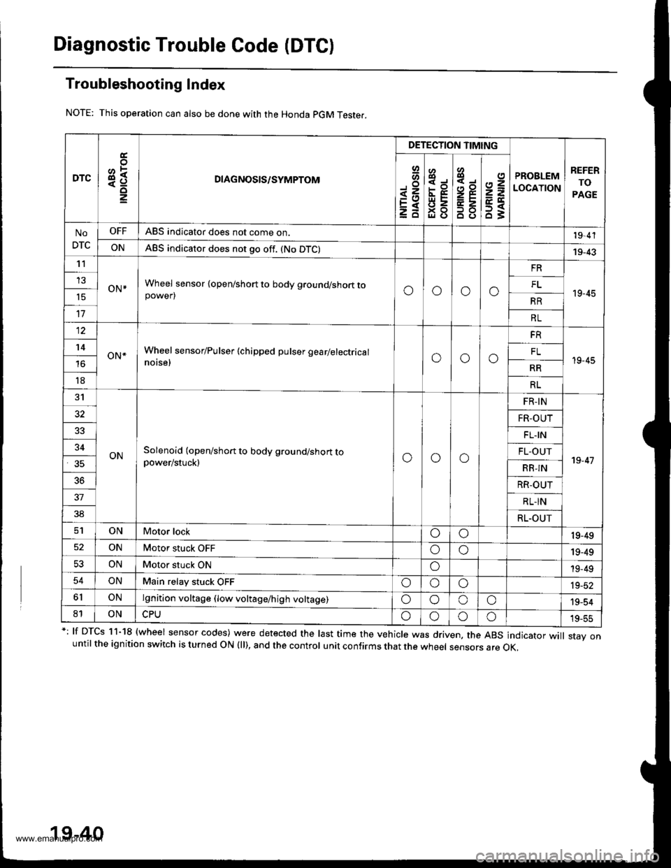
Diagnostic Trouble Code (DTC)
Troubleshooting Index
This operation can also be done with the Honda pGM Teste..
*: lf DTcs 11-18 {wheel sensor codes) were detected the last time the vehicle was driven, the ABs indicator wi
stav onuntil the ignition switch is turned ON (ll), and the control unit confirms that the wheel sensors are OK,
19-40
DTC3R
DETECTION TIMING
PROBLEM
LOCATION
REFER
TO
PAGE
Io
<=EXzd
8
93gl (J
4,,to
B8
2=
ET63
No
DTC
OFFABS indicator does not come on.19,4'l
ONABS indicator does not go off. (No DTC)19-43't1
oN*Wheel sensor {open/short to body ground/short topower)oooo
FR
19-45
13FL't5RR
17RL
12
oN*Wheel sensor/Pulser (chipped pulser gearlelectrical
notse,ooo
FR
19-45
't4FL
RR
18RL
31
ONSolenoid (open/short to body ground/short topower/stuck)ooo
FR-IN
19-47
32FR-OUT
FL.IN
34FL-OUT
RB-IN
36RR-OUT
37RL-IN
38RL.OUT
ONMotor lockoo19-49
ONMotor stuck OFFoo19-49
53ONMotor stuck ONo19-49
54ONMain relay stuck OFFoooia_at
6lONlgnition voltage (low voltage/high voltage)oooo'19-54
81ONoooo19-55
www.emanualpro.com