Page 718 of 1395

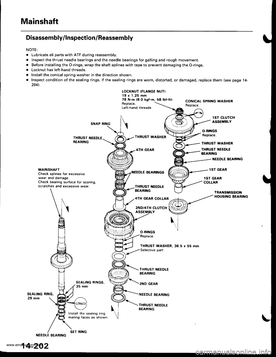
Mainshaft
Disassembly/lnspection/Reassembly
NOTE:
. Lubricate all parts with ATF during reassembly.
.Inspectthethrustneedlebearingsandtheneedlebearingsforgallingandroughmov\
ement,
. Before installing the O-rings. wrap the shaft splines with tape to prevent damaging the O-rings.. Locknut has left-hand threads.
. Install the conical spring washer in the direction shown.
. Inspect condition of the sealing rings. lf the sealing rings are worn, distorted, ordamaged, replace them (see page 14-
2041.
LOCKNUT IFLANGE NUT)19 x 1.25 mm78 N.m {8.O kgf.m,58 lbl.ftlReplace.Left-hand threads
CONICAL SPRING WASHERReplace.
lST CIUTCHASSEMBI.YSNAP RING
THRUST NEEDLEB€ARING
Install the sealing ringmating faces as shown
THRUST WASHEB
4TH GEAR
BEARII{GS
o-Brr{Gs
o-Rtt{GsReplace.
THRUST WASHCR
THRUST NEEOI€BEARIl{G
I{EEDLE BEARIIIG
lST GEARMAINSI{AFTCheck splines for excessivewear ano damage.Check bearing surface tor scoring,scratches and excessive wear.
rST GEARCOLLARTXBUST 1{EEDLEBEARIl{G
4TH GEAR COLLAR
2ND/4TH CLUTCX
TnANSMtSSIOt{HOUSII{G BEARII{G
THRUST WASHER, 36.5 r 55 mmSelective part
SEALING29 mm
THRUST NEEDLESEARING
2NO GEAR
NEEDLE EEARING
THRUST NEEDI-EBEARING
RltrlG,
NEEDLE EEARING
14-202
SET RING
www.emanualpro.com
Page 721 of 1395
Countershaft
Disassembly/lnspection/Reassembly
NOTE:
. Lubricate all pans with ATF before reassembly.
.Inspectthethrustneedlebearingsandtheneedlebearingsforgallingandroughmov\
ement.
. Before installing the O-rings, wrap the shaft spllnes with tape to prevent damaging the O-rings.
. Locknut has left-hand threads.
. Install the conical spring washer in the direction shown.
R€VERSE GEAR
LOCKNUT IFLANGE NUTI23 x 1.25 mm103-0-103N.mCONICAL SPRINGWASHERReplace.t10.5 - 0 -
75.9 - 0 -
Replace.
10.5 kgl.m,75.9 lbt.lr)
Lelt.hand threads
COUNTERSHAFTCheck splines for excessivewear and damage.
REVERSE SELECTORHUB
4TH GEAR
NEEDLE EEARING
NEEOLE BEARING
REVERSESELECTOR
OISTANCE COLLAR.28 mmSelective part
2NO GEAR
lST GEAR
I{EEDLE BEARINGCheck bearing surface for scoring,scratches and excessive wear.lST GEAR COLLAR
TRANSn SSTONHOUSI G BEARING
3RD GEAR
NEEDLE BEARING
3RD GEAR COLLAR
THRUST NEEOLE BEARING
SPLINED WASHER
3RO CLUTCH ASS€MBLY
14-205
www.emanualpro.com
Page 722 of 1395
Gountershaft
Disassembly/Reassembly
1. Remove the reverse selector hub and countershaft
4th gear using a universal two-jaw lor three-jaw)
puller as shown. Place a shaft protector between
the puller and countershaft to prevent damaging
the countershaft.
{Commercially available)
REVERSESELECTOR HUB
.TH GEAR
14-206
2. Assemble the parts on the countershaft as shown
below.
NOTE;
. Lubricate all parts with ATF during reassembly.
. Before installing the O-rings. wrap the shaft
splines with tape to prevent damaging the O-
rings.
4TH GEAR
BEARI'{G
DISTANCE COLLAR, 28 mmSelective oart
GEAR
THRUST ]{EEOL€ AEARIIIG
GEAR COLLAR
THRUST I{EEDLE EEARII{G
WASHER
3RO CLUTCH ASSEMBLY
SEARII{G
O-RINGSReplace.
www.emanualpro.com
Page 726 of 1395
Sub-shaft
Disassembly/lnspection/Reassembly
NOTE:
. Lubricate all parts with ATF before reassembly.
. Inspect the thrust needle bearings and the needle bearings for galling and rough movement.
. Before installing the O-rings, wrap the shaft splines with tape to prevent damaging the O-rings.
6 x 1.0 mrr12 1{.mll.2 ksl.m, 8.7 lbt.ftl
SUB.SHAFTCheck splines tor excessivewear ano damage,Check bearing surlace for scoring,scralches and excessive wear-
t{EEDLE BEARINGSTOP
IST.HOLO CLUTCHASSEMBLY
o,Rtl{GSReplace.
TI{RUST WASI{ER
THFUST TEEOLCBEARI G
I{EEDLE B€ARI G
TRAi{SMTSStON tl()UStNG
14-210
www.emanualpro.com
Page 727 of 1395
Disassembly/Reassembly
1.Remove the ATF guide cap by pushing the sub-shaft
inside the transmission housing.
Remove the 1st-hold clutch assembly by pulling,
then removing the sub-shaft.
Install new O-rings on the sub-shaft.
NOTE: Wrap the shaft splines with tape to prevent
damaging the O-rings.
Place the sub-shaft in the transmission housing,
and install the'lst-hold clutch assembly,
Install the new ATF guide cap using the special
tools. Install it in the direction shown.
ATTACHMENT,32x35mm07746 - 0010t00
14-211
www.emanualpro.com
Page 756 of 1395

Transfer Assembly
Reassembly
NOTE:
. While reassembling the transfer assembly:. Check and adjust the transfer gear tooth contact.. Measure and adjust the transfer gear backlash.. Check and adjust the tapered roller bearing stan-
ing torque.
. Coat all pans with ATF during reassembly.. Replace the tapered roller bearing and the bearing
outer race as a set if either part is replaced.. Replace the transfer drive gear and the transfer dri-ven gear shaft as a set if either part is replaced.
Outline of Assembly
1.Select the 35 mm thrusi shim.
Psrtorm this procedute if the transter driven g€ar
shaft or the tapered roller bearing on the transfer
driven gear shaft is replaced.
Prea$emble the parts to check and adiust transtelgear backlash and transfer gear tooth contact.
Disassemble the parts, then assemble the translerdriven gsar shaft and its related pans.
2.
3.
4. Measure and adjust the starting torque oI the
transfer driven gear shaft tapered roller bearing.
5. Assemble the transfer shaft and its related parts.
6. Measure and adiust the total starting torque.
35 mm Thrust Shim Selection
L Select the 35 mm thrust shim if the transfer drivengear shaft or the tapered roller bearing on the trans-
fer driven gear shaft is replaced.
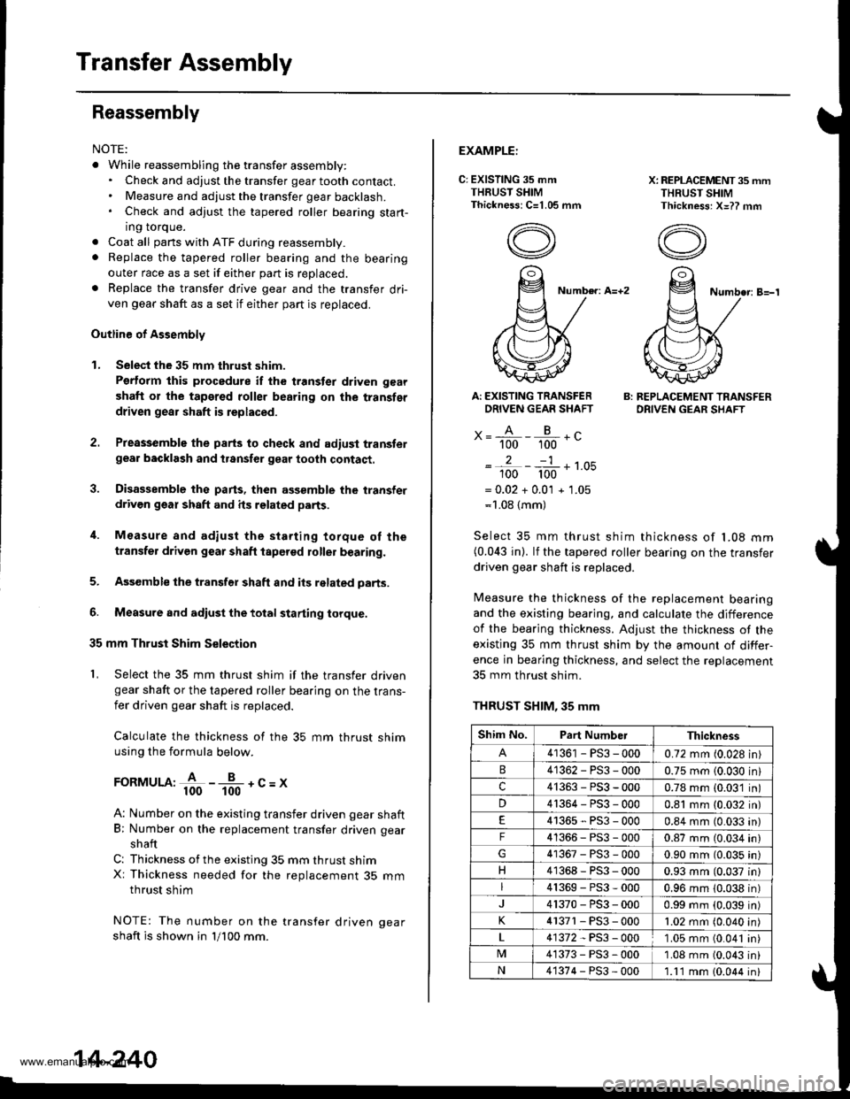
Calculate the thickness of the 35 mm thrust shimusing the formula below.
FoRMULA:+ -*-+c=x
A: Number on the existing transfer driven gear shaft
B; Number on the replacement transfer driven gear
shaft
C: Thickness ofthe existing 35 mm thrust shimX: Thickness needed for the replacement 35 mmthrust shim
NOTE: The number on the transfer driven oear
shaft is shown in 'll100 mm.
14-240
EXAMPLE:
C: EXISTING 35 mmTHRUST SHIMThickness: C=1.05 mm
X: REPLACEMENT 35 mmTHRUST SHIMThickness: X=?? mm
Number: A=+2Numbe.: B=-'l
Ar EXISTING TRANSFERDRIVEN GEAR SHAFT
x= A - B .c" 100 100 -
2-1
100 100 '-
= 0.02 + 0.0'l + 1.05=1.08 {mm)
B: REPLACEMENT TRANSFERDRIVEN GEAR SHAFT
Select 35 mm thrust shim thickness of l�08 mm(0.043 in). lf the tapered roller bearing on the transfer
driven gear shaft is replaced.
Measure the thickness of the replacement bearingand the existing bearing, and calculate the difference
of the bearjng thickness. Adjust the thickness of the
existing 35 mm thrust shim by the amount of differ-
ence in bearing thickness, and select the replacement
35 mm thrust shim.
THRUST SHIM, 35 mm
Shim No.Part NumberThickness
41361 - PS3 - 0000.72 mm (0.028 in)
41362-PS3-0000.75 mm {0.030 in}
c41363-PS3-0000.78 mm (0.03'1 in)
D41364-PS3-0000.81 mm (0.032 in)
41365-PS3-0000.84 mm (0.033 an)
F41366-PS3-0000.87 mm (0.034 in)
41367-PS3-0000.90 mm (0.035 in)
H41368-PS3-0000.93 mm (0.037 in)
41369-PS3-0000.96 mm 10.038 in)
41370-PS3-0000.99 mm (0.039 in)
K4 r371 - PS3 - 0001.02 mm (0.040 in
41372-PS3-0001.05 mm (0.041 in
M41373-PS3-0001.08 mm (0.043 in
N41374-PS3-000'1.11 mm 10.044 in
www.emanualpro.com
Page 771 of 1395

5C.
36.
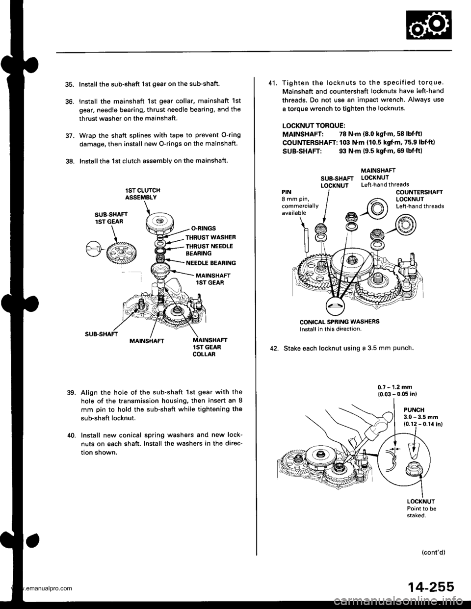
Install the sub-shaft lst gear on the sub-shaft.
Install the mainshaft 1st gear collar, mainshaft 1st
gear, needle bearing, thrust needle bearing, and the
thrust washer on the mainshaft.
Wrap the shaft splines with tape to prevent O-ring
damage, then install new O-rings on the mainshaft
lnstallthe 1st clutch assemblv on the mainshaft
lST CLUTCHASSEMELY
O.RINGS
,te
SUB.SHAFTlST GEAR
.A/.b"'"wt
THRUST WASHER
IHRUST NEEDLEBEANING
NEEDLE BEARING
MAINSHAFT1ST GEAR
MAINSHAFT
39.
1ST GEARCOLLAB
Align the hole of the sub-shaft lst gear with the
hole of the transmission housing, then insert an 8
mm pin to hold the sub-shaft while tightening the
sub-shaft locknut.
40. Install new conical spring washers and new lock-
nuts on each shaft. Install the washers in the direc-
tion shown.
41. Tighten the locknuts to the specified torque.
Mainshaft and countershaft locknuts have left-hand
threads. Do not use an impact wrench. Always use
a torque wrench to tighten the locknuts.
LOCKNUT TOROUE:
MAINSHAFT: 78 N.m (8.0 kgf'm, 58 lbf'ft)
COUNTERSHAFT: 103 N.m (10.5 kgf.m, 75.9 lbf'ft)
SUB-SHAFT: 93 N.m {9.5 kgf'm, 69 lbf'ft|
MAINSHAFT
SU8-SHAFT LOCKNUT
LOCXNUT Left-handthreads
CONICAL SPBING WASH€RSlnstall in this direction-
42. Stake each locknut using a 3.5 mm punch.
0.7 - 1.2 mm
{0.03 - 0.05 inl
PIN8 mm pin,
commerciallyavailable
COUNTENSHAFTLOCKNUTLeft-hand threads
PUNCH3.0 - 3.5 mm10.12 - 0.1il inl
LOCKNUTPoint to bestaked.
(cont'd)
14-255
www.emanualpro.com
Page 773 of 1395

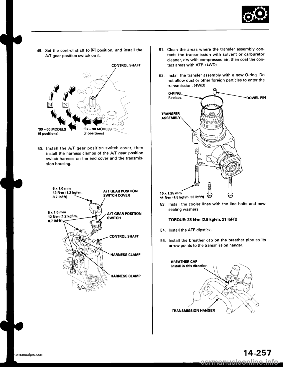
49. Set the control shaft to E position, and install the
A,/T gear position switch on it.
CONTROL SHAFT
l( ((,,, ,.
*
$*\.t+-
NN
6x1.0mm12 N.m 11.2 kgt.m,8.7 tbf.ftl
6xl.0mm12 N.m 11.2 kgf'm,
8,7
'gtt - 00 MoDELS{6 position3}T
Install the A/T gear position switch cover, then
install the harness clamps of the AviT gear position
switch harness on the end cover and the transmis-
sion housing.
50.
CONTROL SHAFT
HARNESS CLAMP
HARNESS CLAMP
Clean the areas where the transfer assembly con-
tacts the transmission with solvent or carburetor
cleaner, dry with compressed air, then coat the con-
tact areas with ATF. (4WD)
Install the transfer assembly with a new O-ring. Do
not allow dust or other foreign particles to enter the
transmission. {4WD)
O.RINGReplace-
10 r 1.25 mma,a N'm 14.5 kgt'm, 33 lbf'ftl
54.
55.
lnstall the cooler lines with the line bolts and new
sealing washers.
TOROUE: 28 N.m 12.9 kgif'm. 21 lbf'ft)
Install the ATF dipstick.
lnstall the breather cap on the breather pipe so its
arrow points to the transmission hanger.
TRANSMISSION
14-257
www.emanualpro.com