1999 HONDA CR-V tow
[x] Cancel search: towPage 144 of 1395
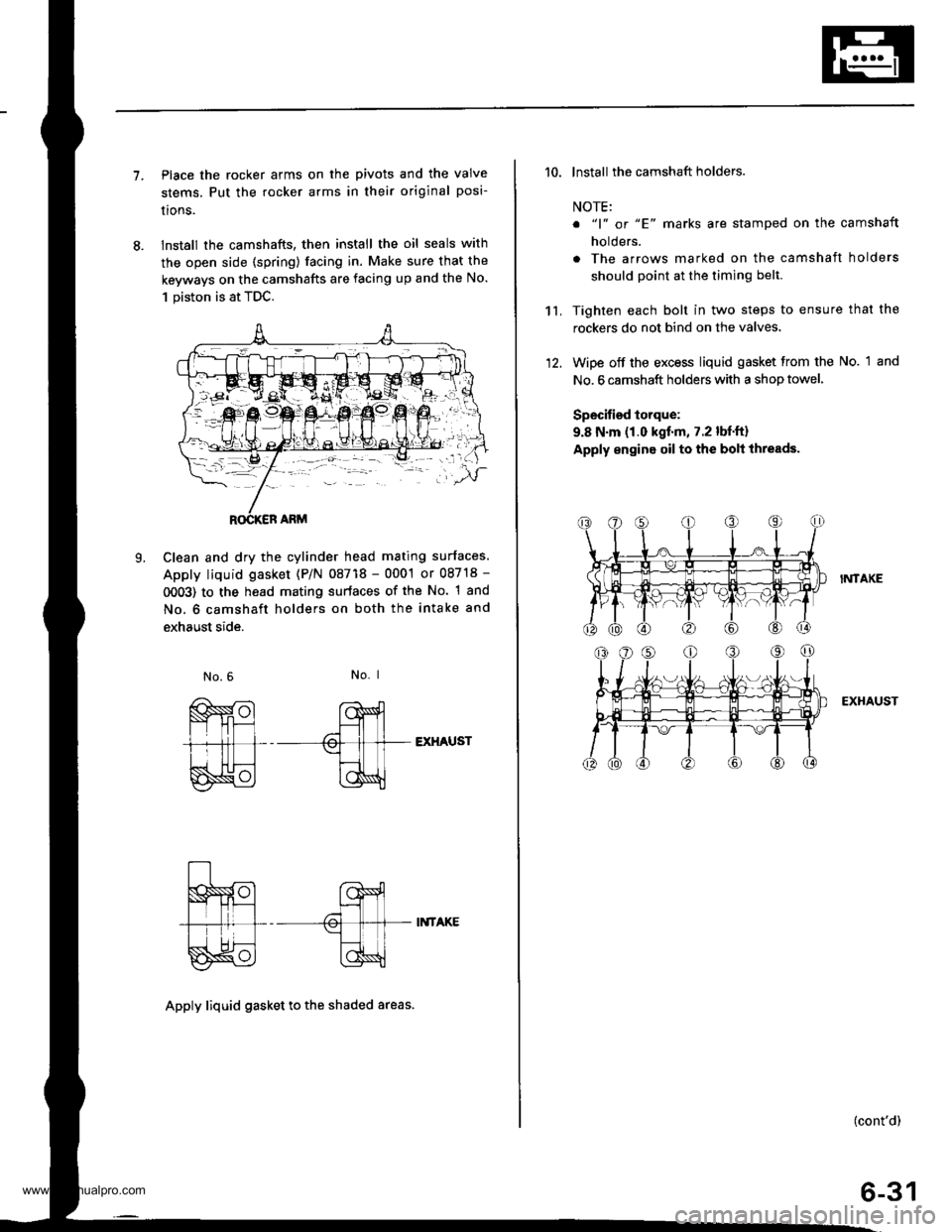
7.Place the rocker arms on the pivots and the valve
stems. Put the rocker arms in their original posi-
lrons.
lnstall the camshafts, then install the oil seals with
the open side (spring) facing in. Make sure that the
keyways on the camshafts are facing up and the No.
1 piston is at TDC.
Clean and dry the cylinder head mating surfaces.
Apply liquid gasket (P/N 08718 - 0001 or 08718 -
0OO3) to the head mating surfaces of the No. 1 and
No. 6 camshaft holders on both the intake and
exhaust side.
L
No. I
EXHAUST
II{TAKE
Apply liquid gasket to th€ shaded areas.
't't,
'10. lnstall the camshaft holders.
NOTE:
o "1" or "E' marks are stamped on the camshaft
holders.
. The arrows marked on the camshaft holders
should point at the timing belt.
Tighten each bolt in two steps to ensure that the
rockers do not bind on the valves.
Wipe off the excess liquid gasket from the No. 1 and
No. 6 camshaft holders with a shop towel,
Specified torque:
9.8 N.m (1.0 kgf.m, 7.2 lbf.ft)
Apply engine oil to the bolt ihreads.
I?,ITAKE
EXHAUST
(cont'd)
6-31
www.emanualpro.com
Page 152 of 1395
Connecting Rod and Crankshaft
End Play
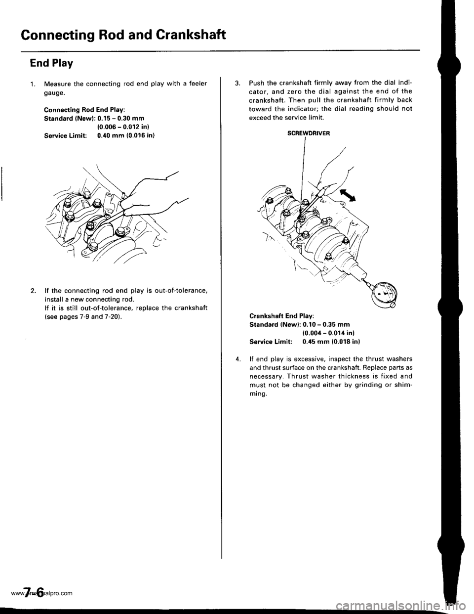
1. Measure the connecting rod end play with a feeler
gauge.
Connecting Rod End Play:
Stsndard (Nsw): 0.15 - 0.30 mm
{0.006 - 0.012 in)
Service Limit: 0./t0 mm 10.016 in)
2. lf the connecting rod end play is out-of-tolerance,
install a new connecting rod.
lf it is still out-of-tolerance, replace the crankshaft
{see pages 7-9 and 7-20).
7-6
3. Push the crankshaft firmly away from the dial indi-
cator, and zero the dial against the end of the
crankshaft. Then pull the crankshaft firmly back
toward the indicator; the dial reading should not
exceed the service limit.
Crankshaft End Play:
Stand.rd (New): 0.10 - 0,35 mm(0.004 - 0.014 inl
Service Limit: 0.45 mm (0.018 inl
4. lf end play is excessive, inspect the thrust washers
and thrust surface on the crankshaft. Reolace oans as
necessary. Thrust washer thickness is fixed and
must not be changed either by grinding or shim-
mrng.
SCREWORIVER
www.emanualpro.com
Page 153 of 1395
Main Bearings
2.
3.
1.
4.
Clearance
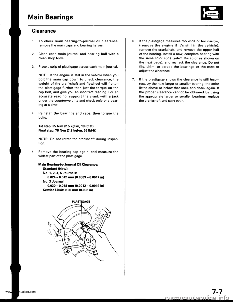
To check main bearing-to-journal oil clearance,
remove the main caps and bearing halves.
Clean each main journal and bearing half with a
clean shop towel.
Place a strip of plastigage across each main journal.
NOTE: lf the engine is still in the vehicle when you
bolt the main cap down to check clearance, the
weight of the crankshaft and flywheel will flatten
the plastigage further than just the torque on the
cap bolt, and give you an incorrect reading. For an
accurale reading, support the crank with a jack
under the counterweights and check only one bear-
Ing aI a Irme.
Reinstall the bearings and caps, then torque the
bolts,
1st step:25 N'm (2.5 kgf.m, 18lbf.ft)
Final siep: 76 N'm 17.8 kgl.m, 56 lbf.ftl
NOTE: Do not rotate the crankshaft during inspec-
tron.
Remove the bearing cap again, and measure the
widest part of the plastigage.
Main Bearing.to.Journal Oil Clearance:
Stand8.d {New):
No. 1,2,4,5 Journsls:
0.02i1- 0.0i12 mm (0.0009 - 0.0017 inl
No. 3 Journal:
0.030 - 0.0i18 mm (0.0012 - 0.0019 inl
Service Limit: 0.06 mm 10.002 in)
lf the plastigage measures too wide or too narrow,(remove the engine if it's still in the vehicle),
remove the crankshaft, and remove the upper half
of the bearing. Install a new, complete bearing with
the same color code (select the color as shown on
the next page). and recheck the clearance, Do not
file, shim, or scrape the bearings or the caps to
adjust the clearance.
lf the plastjgage shows the clearance is still incor-
rect, try the ne)d larger or smaller bearing {the color
listed above or below that one), and check again. lf
the proper clearance cannot be obtained by using
the appropriate larger or smaller bearings, replace
the crankshaft and start over.
7.
7-7
www.emanualpro.com
Page 154 of 1395
Main BearingsConnecting Rod Bearings
Selection
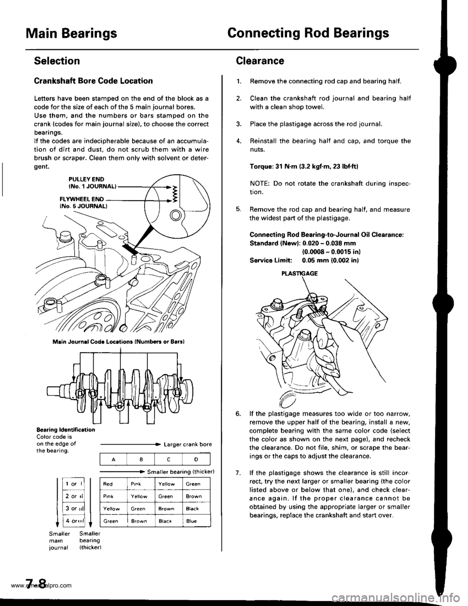
Crankshaft Bore Code Location
Letters have been stamDed on the end of the block as a
code Jor the size of each of the 5 main journal bores.
Use them, and the numbers or bars stamped on the
crank (codes for main journal size), to choose the correct
beanngs.
lf the codes are indecipherable because of an accumula-
tion of dirt and dust. do not scrub them with a wire
brush or sc.aper. Clean them only with solvent or deter-
gent.
Main Journ.l Cod. Locrtions lNumbcB oi Bar3l
Bearing ld.ntif icrtionColor code ison the edge ofthe bearing.
7-8
IcD
"""""""" Smallerbearing(rhicker)
Green
Green
ElaclAlue
Clearance
Remove the connecting rod cap and bearing half.
Clean the crankshaft rod journal and bearing half
with a clean shop towel.
Place the plastigage across the rod journal.
Reinstall the bearing half and cap, and torque the
nuts.
1.
7.
Torqus: 31 N.m (3.2 kgf.m. 23 lbf.ft)
NOTE: Do not rotate the crankshaft during inspec-
tion.
Remove the rod cap and bearing half, and measure
the widest part of the plastigage.
Connesting Rod Bearing-to-Journal Oil Clearancc:
Standard {Newl: 0.020 - 0.038 mm
{0.0008 - 0.0015 in)
Service Limit: 0.05 mm {0.002 inl
lf the plastigage measures too wide or too narrow,
remove the upper half of the bearing, install a new.
complete bearing with the same color code {select
the color as shown on the next page), and recheck
the clearance. Do not file, shim, or sc.ape the bear-
ings or the caps to adjust the clearance.
lf the plastigage shows the clearance is still incor
rect, try the next larger or smaller bearing {the color
listed above or below that one). and check clear-
ance again. lf the proper clearance cannot be
obtained by using the appropriate larger or smaller
bearings. replace the crankshaft and start over.
PLASTIGAGE
www.emanualpro.com
Page 203 of 1395
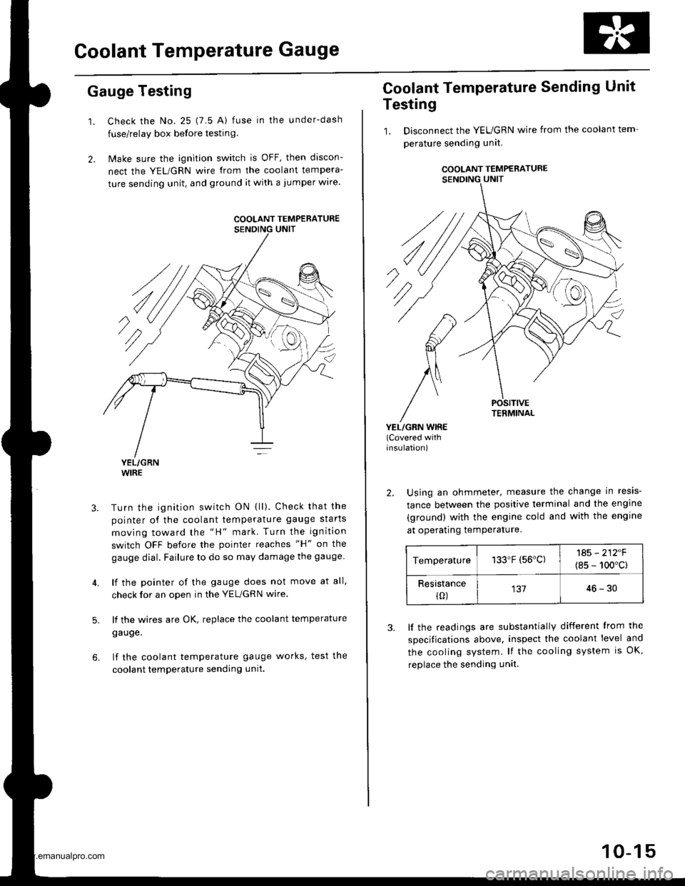
Goolant Temperature Gauge
Gauge Testing
1. Check the No. 25 (7.5 A) fuse in the under-dash
fuse/relay box before testin9.
2. Make sure the ignition switch is OFF, then discon-
nect the YEL/GRN wire from the coolant tempera-
ture sending unit. and ground it with a jumper wire.
YEL/GRNWIRE
Turn the ignition switch ON {ll). Check that the
pointer of the coolant temperature gauge starts
moving toward the "H" mark. Turn the ignition
switch OFF before the pointer reaches "H" on the
gauge dial. Failure to do so may damage the gauge.
lf the pointer of the gauge does not move at all,
check for an open in the YEL/GRN wire.
lf the wires are OK, replace the coolant temperature
gauge.
lf the coolant temperature gauge works, test the
coolant temperature sending unit.
5.
COOLANT TEMPERATURE
Coolant Temperature Sending Unit
Testing
1. Disconnect the YEUGRN wire from the coolant tem
perature sending unit.
COOLANT TEMPERATURE
POSITIVETERMINAL
YEL/GRN WIRE(Covered withinsulation)
2. Using an ohmmeter, measure the change in resis-
tance between the positive terminal and the engine
(ground) with the engine cold and with the engine
at operating temPerature.
Temperature133.F (56'C)1A5 - 212F
(8s - 100'c)
Resistance(0)13746-30
3. lf the readings are substantially different from the
specitications above, inspect the coolant level and
the cooling system. lf the cooling system is OK,
replace the sending unit.
10-15
www.emanualpro.com
Page 326 of 1395
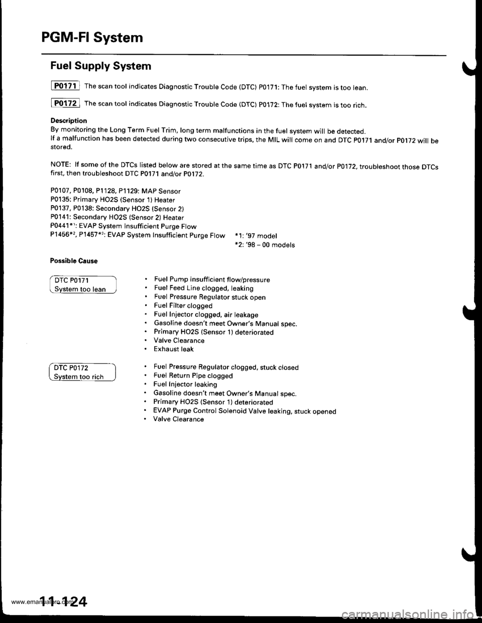
PGM-FI System
Fuel Supply System
[POliil The"""ntool indicates Diagnostic Troubte Code (DTC) p0'171:Thefuet system istoo lean.
[Fo17ZJ rh""""ntool indicates Diagnostic Troubte code {DTc) p0172:Thefuel svstem istoorich.
Description
By monitoring the Long Term Fuel rrim, long term malfunctions in the fuel system will be detected.lf a malfunction has been detected during two consecutive trips, the MIL will come on and DTc p0171 and/or pol72 will bestored.
NOTE: lf someof the DTCS listed below are stored atthesametimeas DTC P017'l and/or p0172, troubleshoot those DTcsfirst, then troubleshoot DTC P0171 and/or PO1i2.
P0107, P0108, P1128, P'1129: MAP Sensor
P0135: Primary HO2S (Sensor 1)Heater
P0137, P0138: Secondary HO2S {Sensor 2)P0141: Secondary H02S (Sensor 2) Heater
P0441*r: EVAP System lnsufficient Purge FtowP1456*,, P'l457 *?i EVAP System Insufficient purge Ftow
Possible Cause
DTC P0171
too lean
*1: '97 model*2: '98 - 00 models
Fuel Pump insufficient flow/pressure
Fuel Feed Line clogged. leaking
Fuel Pressure Regulator stuck openFuel Filter clogged
Fuel Injector clogged, air leakage
Gasoline doesn't meet Owner's Manual spec.Primary HO2S (Sensor 1) deteriorated
Valve Clearance
Exhaust leak
Fuel Pressure Regulator clogged, stuck closedFuel Return Pipe clogged
Fuel Injector leaking
Gasoline doesn't meet Owner's Manual spec.Primary H02S (Sensor 1) deteriorated
EVAP Purge Control Solenoid Valve leaking, stuck openedValve Clearance
DTC P0172
flch
11-124
www.emanualpro.com
Page 377 of 1395
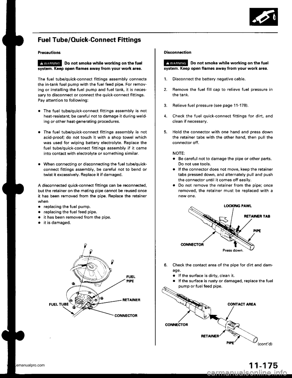
Fuel Tube/Ouick-Gonnect Fittings
Procautions
@ Do not smoke whils working on the fuel
syst6m, Koop open flames away from your work ar9a.
The fuel tube/quick-connect fittings assembly connects
the in-tank fuel pump with the fuel feed pipe. For remov-
ing or installing the fuel pump and fuel tank, it is neces-
sary to disconnect or connect the quick-connect fittings.
Pay attention to following;
. The fuel tube/quick-connect fittings assembly is not
heat-resistant; be careful not to damage it during weld-
ing or other heat-generating procedures.
. The fuel tube/quick-connect fittings assembly is not
acid-proof; do not touch it with a shop towel which
was used for wiping battery electrolyte. R€place the
fuel tube/quick-connect fittings assembly if it came
into contact with electrolyte or somethino similar.
. When connecting or disconnecting the fuel tube/quick-
connect fittings assembly, be careful not to bend or
twist it excessively, Replace it if damaged,
A disconnected quick-connect fittings can be reconnected,
but the retainer on the mating pipe cannot be reused once
it has been removed from the pipe. Replace tha retainer
. replacing the fuel pump.
. replacing the fuelfeed pipe,
. it has been removed from the Dioe,
. it is damaged.
RCTAINERFUEL TUBE
CONNECTOR
CONNECTOR
RETAINER
11-175
Disconnection
!@ Do not smoke while working on the fuel
syst6m. Keep open flames away from your work area.
1. Disconnect the battery negative cable.
2. Remove the fuel fill cap to relieve fuel pressure in
the tank.
3. Relieve fuel pressure (see page 11-178).
4. Check the fuel quick-connect fittings for dirt, and
clean if necessary.
5. Hold the connector with one hand and press down
the retainer tabs with the other hand. then pull the
connector off.
NOTE:
. Be careful not to damage the pipe or other parts.
Do not use tools,
. lf the connector does not move, keep the retainer
tabs pressed down, and alternately pull and push
the connector until it comes off easily.
. Do not remove the retainer from the pipe; once
removed, the retainer must be replaced with a
new one.
LOCKII{G PAWL
RETANEN TAB
@NNCCTOR
Press down.
6. Check the contact area of the pipe for dirt and dam-
age.
. lf the surface is dirW, clean it
. lf the surface is rusty or damaged, replace the fuel
pump or fuel feed pipe,
CONTACT ANEA
{cont'd}
www.emanualpro.com
Page 380 of 1395
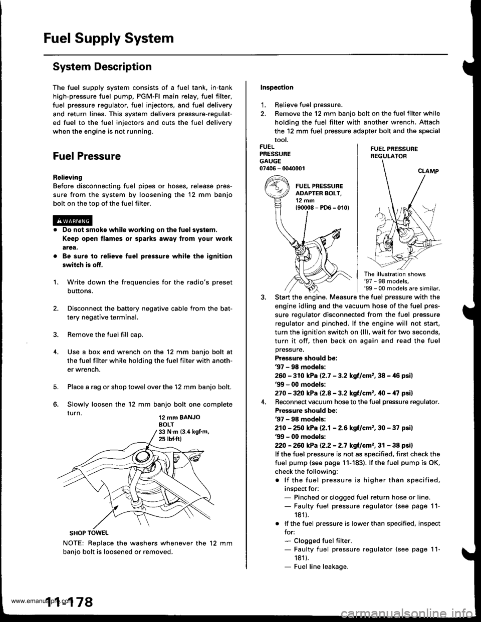
Fuel Supply System
System Description
The fuel supply system consists of a fuel tank, in-tank
high-pressure fuel pump. PGM-Fl main relay, fuel filter,
fuel pressure regulator, fuel injectors, and fuel delivery
and return lines. This system delivers pressure-regulat-
ed fuel to the fuel injectors and cuts the fuel delivery
when the engine is not running.
Fuel Pressure
Relieving
Before disconnecting fuel pipes or hoses, release pres-
sure from the system by loosening the 12 mm banjo
bolt on the too of the fuel filter.
Do not smoke while working on the fuel system.
Ke€p open flames or sparks away from your work
area,
Be sure to relieve fuel pressure while the ignition
switch is off.
Write down the frequencies for the radio's preset
buttons.
Disconnect the battery negative cable from the bat-
tery negative terminal.
Remove the fuel fill cap.
Use a box end wrench on the 12 mm banjo bolt at
the fuel filter while holding the fuel filter with anoth-
er wrench.
Place a rag or shop towel over the '12 mm banjo bolt.
Slowly loosen the 12 mm banjo bolt one complete
rurn 12 mm BANJoBOLT
1.
SHOP TOWEL
NOTE: Replace the washers whenever the 12 mm
banio bolt is loosened or removed.
11-178
Inspection
1, Relieve fuel pressure.
2. Remove the 12 mm banjo bolt on the fuel filter while
holding the fuel filter with another wrench. Attach
the 12 mm fuel pressure adapter bolt and the special
tool.
FUEL PRESSUREREGULATON
FUELPRESSUREGAUGE07406 - 0040001
The illustration shows'97 - 98 models,'99 - 00 models are similar.
Start the engine. Measure the fuel pressure with the
engine idling and the vacuum hose of the fuel pres-
sure regulator disconnected from the fuel pressure
regulator and pinched. lf the engine will not start,
turn the ignition switch on (ll), wait for two seconds,
turn it off, then back on again and read the fuel
pressure.
Pressure should be:'97 - 98 mod€ls:
260 -31O kPa 12.7 - 3.2 kgf/cm,, 38 - 46 psil'99 - 0O models:
270 - 32O kPa Q.A - 3.2 kgf/cm'�, ifo - /U psil
Reconnect vacuum hose to the fuel pressure regulator.
Prgs3ure should be:'97 - 98 models:
210 - 25O kPa 12.1- 2.6 kgf/cm'�, 30 - 37 psi)'99 - 00 models:
22O -26iJ kPa 12.2 - 2.7 kgt/cm'�, 31 - 38 psi)
lf the fuel pressure is not as specified, first check the
fuel pump (see page 11- 183). lf the fuel pump is OK,
check the following:
. lf the fuel pressure is higher than specified,
inspect for:- Pinched or clogged fuel return hose or line.- Faulty fuel pressure regulator (see page 11-
181).
. lf the fuel pressure is lower than specified. inspect
for:- Clogged fuel filter.- Faulty fuel pressure regulator (see page 11-
1811.- Fuel line leakage.
www.emanualpro.com