Page 189 of 1395
Cooling
f ffustrated Index ........... ..... 1O-2
Radiator
Rep|acement ...........,....,...................... 10-4
Engine Coolant Refilling and
Bleeding ..,.,................. 10-5
Cap Testing .................... 10-7
Testing ......10-7
Thermostat
Rep|acement ....................................... 10-8
Testing ...... 10-9
Water Pump
lllustrated lndex ....,..... .. 10-10
Inspection . 10-1 1
Replacement ....................................,.. 10-1 1
Fan Gontrol
Component Location Index ............... 10-12
Circuit Diagram ............. 10-13
Fan Motor Testing ......... 10-14
Radiator Fan Switch Testing ............. 10-14
Coolant Temperature Gauge
Gauge Testing ............... 10-15
Coolant temperature Sending
Unit Testing ........,....... 10-15
www.emanualpro.com
Page 201 of 1395
Circuit Diagram
UNDER OASHFUSEiRELAY BOX
6; E;';lwHTsLka rtF',*",El-l
I
RAOIATORFANSWITCHfClosed :Above)L 199oF {930C) J
BLK/RED
I
L^,^,.,
T*'
IBLK
I
I
oro,
IGNITION SWITCH
No.41{100A) N0.42140A)
www.emanualpro.com
Page 386 of 1395

Fuel Supply System
Fuel Gauge
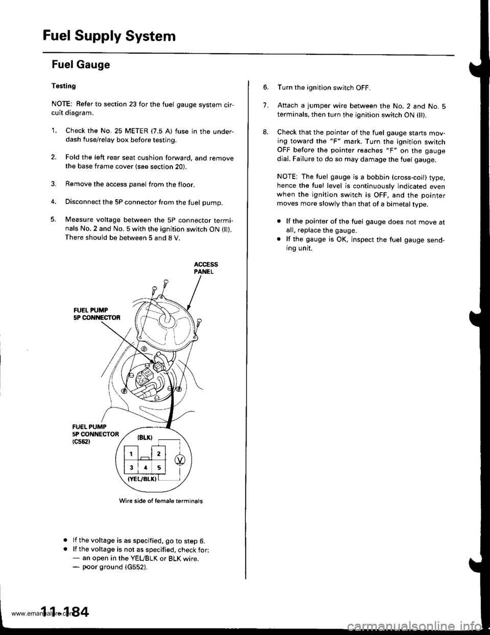
Tssting
NOTE: Refer to section 23 for the fuel gauge system cir-cuit diagram.
'1. Check the No. 25 METER (7.5 A) fuse in the under-dash fuse/relay box before testing.
2. Fold the left rear seat cushion forward, and remove
the base frame cover {see section 20).
3. Remove the access panel from the floor.
4. Disconnect the 5P connector from the fuel pump.
5. Measure voltage between the 5P connector termi-nals No.2 and No. 5 with the ignition switch ON ( ).There should be between 5 and 8 V.
FUEL PUMP5P CONNECTOR
tc56al
a
a
Wire side of female t€rminals
lf the voltage is as specified, go to step 6.lf the voltage is not as specified, check for:- an open in the YEUBLK or BLK wrre.- poor ground (c552).
11-184
7.
Turn the ignition switch OFF.
Attach a jumper wire between the No. 2 and No. 5terminals, then turn the ignition switch ON fll).
Check that the pointer of the fuel gauge starts mov-ing toward the "F" mark. Turn the ignition switchOFF before the pointer reaches "F" on the gauge
dial. Failure to do so may damage the luel gauge.
NOTE: The fuel gauge is a bobbin (cross-coil) type,hence the fuel level is continuously indicated evenwhen the ignition switch is OFF, and the pointer
moves more slowly than that of a bimetal type.
. lf the pointer of the fuel gauge does not move atall. replace the gauge.
. lf the gauge is OK, inspect the fuel gauge send-ing unit.
www.emanualpro.com
Page 537 of 1395
Circuit Diagram and Terminal Locationsr9T Model
IGNITIONSWITCH
LOC( UPCONTROL
LOCK UPCONTROLSOLEITOIDVALVE B
sf Frc0|lltF0LSOLENOIDVALVE A
sHrFr c0r{TnoLSOLEI{OID VALVE B
UNEASSOLINOID
14-21
www.emanualpro.com
Page 538 of 1395
Description
Electronic Control System (cont'd)
Circuit Diagram and Terminal LocationsrgS Model
GNTIONSWITCN
LOCK-UPCONIFOLSOLEIIO D VALVE A
LOCK-UPCONTSOLSOLEI.IO 0 vALvE B
SBIFICONTROLSOLEI€ DVALVE A
SH FTCONTFOLSOLEiDID VALVE 8
LIN€AA SOL€iDIDGNIION SWTCHtGr
14-22
www.emanualpro.com
Page 539 of 1395
Circuil Diagram and Terminal Locations-'gg - 00 Models
GN'ION SWITCN
LOC( UP C,ONTROLSOLEID D VALVE A
LOCK.UPCON'IFO!SOLENOIOVALVE B
SNIFT CONTAOTSOL€NOID VALVE A
SH]FT CONTROLsolEtiroro vArvE B
L NEAF SOLEI{OIO
pG2
IGPI
IGP2
vcc2
rGNloN SWrlCHGI
PCM Conn€clor Tehrial Loaabm
14-23
www.emanualpro.com
Page 562 of 1395
PCM Circuit Diagram (A/T Control System)
'97 Model
UNDER.I]OOD FUSAFELAY BOXEATTEFY
_YEL_
T-l ,
TT-l
t_-:
G101
'Fr-r.04
P- r.-or..u L_a TMEALOC(BrK€ru -<< calTFoL
P_ *+rr
F- onmrxCFUISECONTFOLUNITf-"".>
| ["'"]
I l,[-l
III ;,
F_ pw
P_ eLu
F-- enN
UNDER DASN
M 25(7.54)
IGNITONSWITCH UNDEF OASNFUSAFELAYSOX
oowEa-qar. cor.lFo- MooLrE rpcMr F &*1 r*--'l_____O_=_ATP IO! ,ATP . ATD , A-P , A-P , A-PNP lrNo lR 101 103 12 ll
Ar'TGEAR POS]TIONswtcN
14-46
www.emanualpro.com
Page 566 of 1395
PCM Circuit Diagram (A/T Gontrol System)
'98 Model
UNOEF-HOOO FUSAFELAY sox
_YEL_
09 lD0 lDl,l lDl5
PNK BLU
F rronr
f-'r'------}-'er'
F_ cRN _______]_f- PN(
F_ GFNTBLX
F_ gnN
*,',,,)83Hf'L
f *'-> 3111"?"
I
1*[-lll-,I I Gro]
UNOEF-DASHFUSE/BELAYBOX
I
rGD2 I ocr I oG2 | V8 S0. I SIOP SW I CAs
ATP IDl ,ATP , ATP , A-P , ATP , A_PNP lrND lR lD4 lD3 12 ll
sr{rTat
14-50
www.emanualpro.com