1999 HONDA CR-V brake light
[x] Cancel search: brake lightPage 371 of 1395
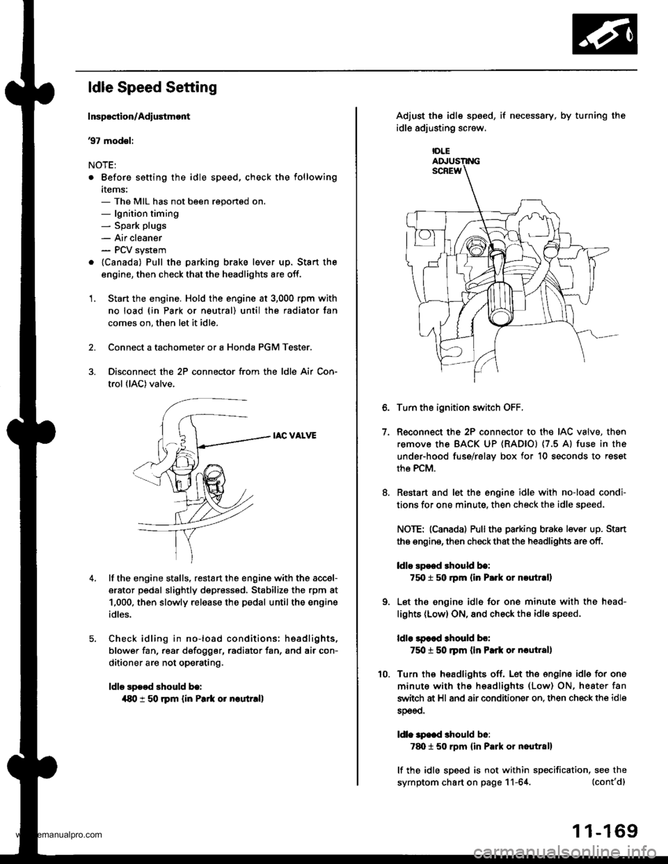
ldle Speed Setting
Inspoction/Adiustmont
37 modsl:
NOTE:
. Before setting the idle speed, check the following
items:- The MIL has not been reportsd on.- lgnition timing- Spark plugs
- Air cleaner- PCV system
. lcanada) Pull the parking brake lever up. Stan the
engine, then check that the headlights are off.
1. Start the engine. Hold the engine at 3,000 rpm with
no load (in Park or neutral) until the radiator fan
comes on, then let it idle.
Connect a tachometer or a Honda PGM Tester.
Disconnect the 2P connector from the ldle Air Con-
trol (lAC) valve.
IAC VALVE
lf the engine stalls, restart the engine with the accel-
erator pedal slightly depr6ss6d, Stabilize the rpm at
1,000, then slowly release the pedal until the engine
idles.
Check idling in no-load conditions: hsadlights,
blower fan, rear d€fogger, radiator fan, and air con-
ditioner are not operating.
ldle spood should b.:
{80 t 50 rpm {in Park or noutr.ll
IDLE
7.
Adjust the idle sp6ed,
idle adjusting screw.
if necessary, by turning the
Turn the ignition switch OFF.
Reconnect the 2P connector to the IAC valve, then
remove the BACK UP (RAD|Ol (7.5 Al fuse in the
under-hood fuse/rslav box for 10 seconds to reset
the PCM.
Restart and let the engine idle with no-load condi-
tions for one minute, then check the idle speed.
NOTE: (Canadal Pullthe parking brake lever up. Stan
the engine, then check that the headlights are off.
ldlo Ep€ed rhould be:
75O t 50 rpm (in P.rk or noutr.ll
Let the engine idl6 for one minute with the head-
lights (Low) ON, and check th€ idl€ speed.
ldle lpcod 3hould bo:
750 t 50 ]pm (in Park or nautlal)
Turn the headlights off. Let th€ engine idle for one
minute with the headlights (Low) ON, heater fan
switch at Hl and air conditioner on. then check the idle
sDeeo.
ldl. specd should b6:
7d) 1 50 rpm {in Park or nautral}
lf the idle speed is not within specification, see the
symptom chart on page 11-64. (cont'd)
1 1-169
www.emanualpro.com
Page 401 of 1395
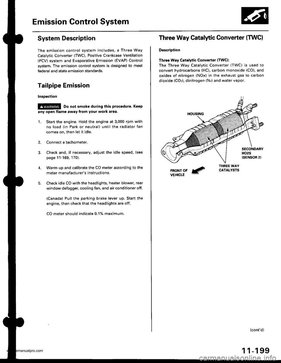
Emission Control System
System Description
The emission control system includes, a Three Way
Catalytic Converter {TWC), Positive Crankcase Ventilation
(PCV) svstem and Evaporative Emission (€VAP) Control
system. The emission control system is designed to meet
federal and state emission standards.
Tailpipe Emission
Inspsction
!@ Do not smoke during this procsdura. Keep
any open tlame away from your work area.
1. Start the engine. Hold the engine at 3,000 rpm with
no load (in Park or neutral) until the radiator fan
comes on, then let it idle,
Connect a tachometer.
Check and, if necessary, adjust the idle speed, (see
page 11-169, 170).
Warm up and calibrate the CO meter according to the
meter manufacturer's instructions.
Check idle CO with the headlights, heater blower, rear
window defogger, cooling fan, and air conditioner off.
(Canada) Pull the parking brake lever up. Start the
engine, then check that the headlights are off.
CO meter should indicate 0.1% maximum.
4.
Three Way Catalytic Converter (TWCI
DsscriDtion
Three Way Catalytic Convertsr lTwcl:
The Three wav Catalvtic Converter (TWC) is used to
convert hydrocarbons (HC), carbon monoxide (CO), and
oxides of nitrogen (NOx) in the exhaust gas to carbon
dioxide (COr), dinitrogen (Nr) and water vapor,
{cont'd)
1 1-199
www.emanualpro.com
Page 446 of 1395
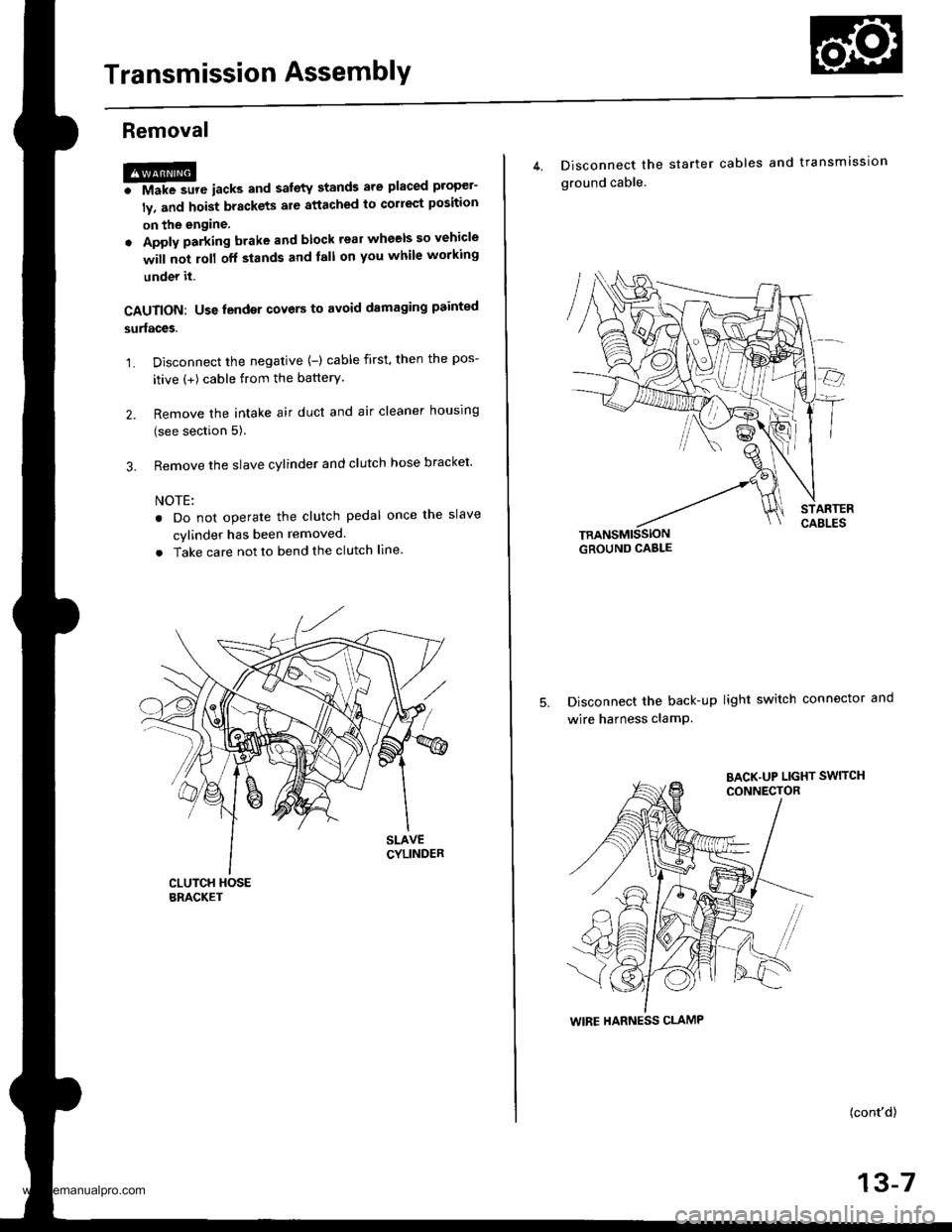
Transmission AssemblY
Removal
@FMak. sw. iack" and safety stands are placed propel-
ly, and hoist brackets are attached to collect position
on the engine,
. Apply parking brake and block rear wheels so vehicle
will not roll off stands and lall on you while working
under it.
CAUTION: Use fender covers to avoid damaging painted
surfaces.
1. Disconnect the negative {-) cable first, then the pos-
itive (+) cable from the batterY.
2. Remove the intake air duct and air cleaner houslng
(see section 5).
3. Remove the slave cylinder and clutch hose bracket'
NOTE:
. Do not operate the clutch pedal once lhe slave
cvlinder has been removed.
. Take care not to bend the clutch line.
4. Disconnect the
ground cable.
starter cables and transmission
TRANSMISSIONGROUND CABLE
Disconnect the back-up light switch connector and
wire harness clamP.
(cont'd)
13-7
WIRE HARNESS CLAMP
www.emanualpro.com
Page 565 of 1395

PCM CONNECTOR B (25P) lcont'd)
PCM CONNECTOR C {31PI
PCM CONNECTOR D II6PI
Terminal NumbelSignalDescriptionMeasuring Conditions/Terminal voltage
811SHBShift control solenoid valve B
control
In E, E position, in 1st and 2nd gear in -q,
Er position: Battery voltage
In B position, in 3rd gear in qd, q:l,in atn
gear in D. position: 0 V
812ILUlnterlock controlWhen ignition switch is ON (ll), brake pedal
deDressed and accelerator oedal released:0 V
B13D4 INDD4 Indicator light controlWhen ignition switch is first turned ON (ll): 6 V
or more for tlvo seconds
In lDll position: 6V or more
814NMSGMainshaft speed sensor ground
815NMMainshaft speed sensor signal
InpuI
Depending on engine speed: Pulsing signal
When engine is stopped: 0 V
816ATP RAy'T gear position switch Eposition signal input
In E position; OV
In other than E position: Battery voltage
817ATP 2Ay'T gear position switch E posi-
tion signal input
InEposition:0V
In other than E position: Battery voltage
B18ATP 1A/T gear position switch El posi-
tion signal input
InEposition:0V
In other than E position: Battery voltage
819 to 821Not used
B�22NCSGCountershaft speed sensor ground
NCCountershaft speed sensor signal
Inpur
Depending on vehicle speed: Pulsing signal
when vehicle is stooped: 0 V
824ATP D4A/T gear position switch iql posi-
tion signal input
In E position: 0V
In other than lgal position: Baftery voltage
825ATP NPAy'T gear position switch E and
N position signals input
In E and E positions: 0V
In otherthan @ and ffi positions:5 V
Terminal NumberSignalDescriptionMeasuring Conditions/Terminal Voltage
SCSService check signalWith ignition switch ON (ll) and service check
connector open: 5 V
With ignition switch ON (ll) and service check
connector connected with special tool: 0 V
c10VBUBack-up power system(under-hood Fuse 47)
Always battery voltage
Terminal NumberSignalDescriptionMeasuring Conditions/Terminal Voltage
STOP SWBrake switch signal inputBrake pedal pressedr Battery voltage
Brake pedal released: 0 V
14-49
www.emanualpro.com
Page 570 of 1395

PCM Terminal Voltage/Measuring Conditions
A/T Control System -'98 - 00 Models
The PCM terminal voltage and measuring conditions are shown for the connector terminals that are related to the A"/T con-
trol system. The other PCM terminal voltage and measuring conditions are described in section 11.
FCM Connector Terminal Localions
NOTE: 819 and C3 terminalsare applied to'99 - 00 models.
o (16Pt
T6rminal NumberSignalDescriptionMeasuring Conditions/Terminal Voltage
A5CRSDownshift signal input from
cruise control unit
When cruise control is used; Pulsing signal
A10scsTiming and adjustment service
check signal (5 V from PCM)
With ignition switch ON (ll) and service check
connector open:5 V
With ignition switch ON (ll) and service check
connector jumped with special tool: 0 V
A14('98 model)
D4 INDD4 indicator light control
{Voltage from PCM turns D4 light
oN)
When ignition switch is first turned ON (ll):
Battery voltage for two seconds
In E position: Battery voltage
A14
('99 - 00 models)
D INDD indicator light control(Voltage from PCM turns D light
oN)
When ignition switch is first turned ON (ll):
Baftery voltage for two seconds
ln E position: Battery voltage
428ILUInterlock control(Voltage from PCM)
When ignition switch ON {ll), brake pedal
depressed, and accelerator pedal released:
Battery voltage
A.32STOP SWBrake switch signal inputBrake pedal pressed; Battery voltage
Brake pedal released: 0 V
FCM CONNECTOR B I25P}
Terminal NumberSignalDescriptionMeasuring Conditions/Terminal Voltage
B1IGPlPower supply circuit from main
relay via under-hood Fuse 44
With ignition switch ON {ll): Battery voltage
With ignition switch OFF: 0 V
82PG1Ground (G101)
B8LSMLinear solenoid power supply
negative electrode
IG P2Power supply circuit from main
relay
With ignition switch ON (ll): Baftery voltage
With ignition switch OFF: 0 V
810PG2Ground (G101)
B17Linear solenoid power supply
positive electrode
With ignition switch ON (ll): Pulsing signal
819
('99 - 00 models)
O/D INDOver-Drive (O/D) OFF indicator
light control
When ignition switch is first turned ON (ll):
0 V for two seconds
O/D OFF indicator light ON:0 V
O/D OFF indicator light OFF: Battery voltage
s20Ground (G101)
B�21VBUBack-up power supply(under-hood Fuse 47)
Always battery voltage
B�22LG2Ground (G101)
14-54
www.emanualpro.com
Page 577 of 1395
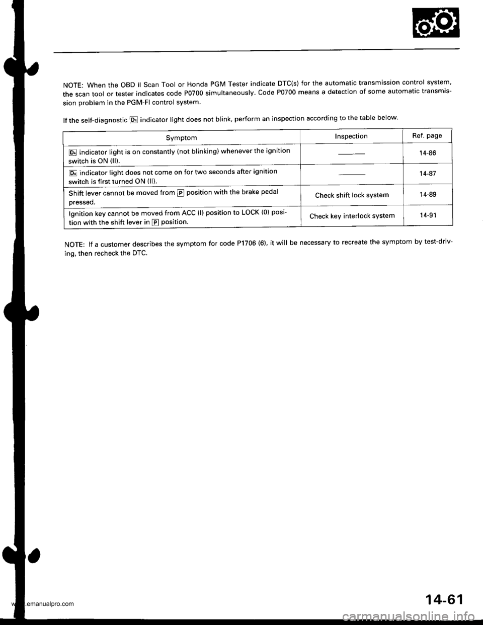
NOTE: When the OBD ll Scan Tool or Honda PGM Tester indicate DTC(s) for the automatic transmission control system'
the scan tool or tester indicates code P0700 simultaneously. code P07oo means a detection of some automatic transmis-
sion problem in the PGM-Fl control system
lf the self-diagnostic E indicator light does not blink, perform an inspection according to the table below.
NOTE: lf a customer describes the symptom for code P1706 (6), it will be necessary to recreate the symptom by test-driv-
ing, then recheck the OTC.
SymptomInspectionRef. page
E indicator light is on constantly (not blinking) whenever the ignition
switch is ON (ll).14-86
E indicator light does not come on for two seconds after ignition
switch is first turned ON (ll).
't 4-41
Shift lever cannot be moved from @ position with the brake pedal
Dressed,Check shift lock system14-89
lgnition key cannot be moved from ACC (l) position to LOCK {0) posi
tion with the shift lever in E position.Check keY interlock system14-91
14-61
www.emanualpro.com
Page 579 of 1395
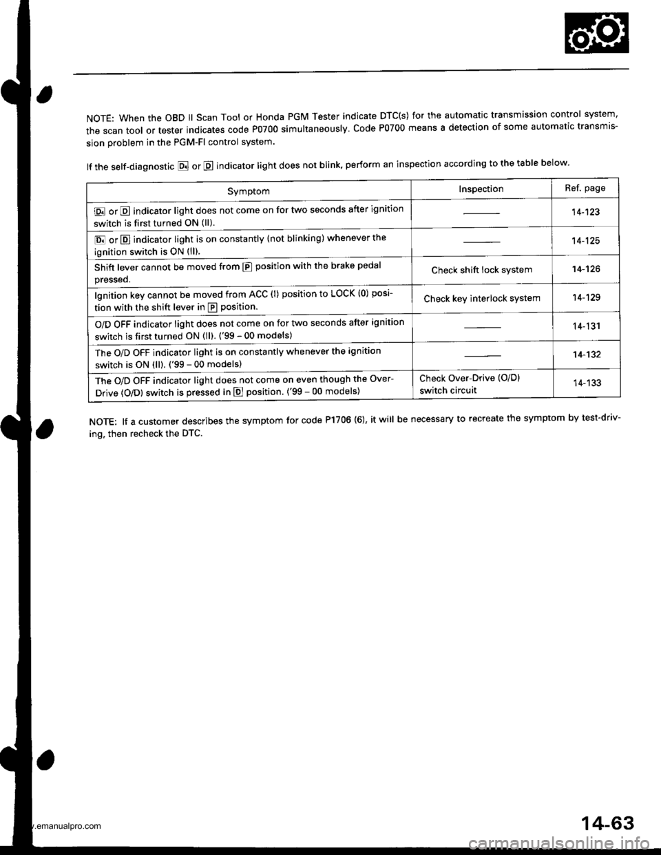
NOTE: When the OBD ll Scan Tool or Honda PGM Tester indicate DTC(S) for the automatic transmission control system,
the scan tool or tester indicates code P0700 simultaneously. Code P0700 means a detection of some automatic transmis-
sion problem in the PGM-Fl control system.
lf the self-diagnostic E or E indicator light does not blink, perform an inspection according to the table below.
NOTE: lf a customer describes the symptom for code P17OO (6), it will be necessary to recreate the symptom by test-driv-
ing. then recheck the DTC.
SymptomInspectionRef. page
E or E indicator light does not come on for two seconds after ignition
switch is first turned ON (ll).14-123
E or E] indicator light is on constantly (not blinking) whenever the
ignition switch is oN {ll).
14-125
Shift lever cannot be moved from E position with the brake pedal
presseo.Check shift lock system14-'t26
lgnition key cannot be moved from ACC (l) position to LOCK (0) posi-
tion with the shift lever in E position.Check key interlock system14-129
O/D OFF indicator light does not come on for two seconds after ignition
switch is first turned ON (ll). ('99 - 00 models)14-131
The O/D OFF indicator light is on constantly whenever the ignition
switch is ON (ll). ('99 - 00 models)14-132
The O/D OFF indicator light does not come on even though the Over-
Drive (O/Dl switch is pressed in E position. ('99 - 00 models)
Check Over-Drive {O/D}
switch circuit14-133
14-63
www.emanualpro.com
Page 605 of 1395
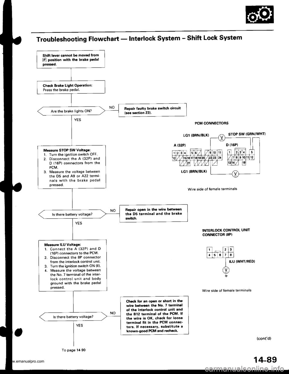
Troubleshooting Flowchart - Interlock System - Shift Lock System
PCM CONNECTORS
Wire side of lem6le termanals
INTERLOCK CONTROL UNIT
CONNECTOR I8P)
ILU IWHT/REDI
(cont'd)
Shift lever cannot be moved from
E] position with the brake P€delpreiseo.
Chock Brake Light Operation:Press the brake pedal.
Repsir fauhy brake switch circuit
{seo s€ction 231.Are the brake lights ON?
M€asure STOP SW voltage:l� Turn the ignition switch OFF.
2. Disconnect the A (32P) and
D (16P) connectors lrom thePCM.3. Measlre the voltage between
the D5 and Ag or A22 terma
nals with the brake Pedalpressed,
Repair opon in the wi.e be{w.enthe D5 terminal and the br.ke
switd!.
Measur€ ILU vohage:1. Connect the A {32P) and D
116P) connectors to the PCM.2. Disconnect the 8P connectorfrom the interlock control unit
3. Turn the ignition switch ON (ll).
4. Measure the voltage betweenthe No.7 terminalofthe inter
lock control unit and bodyground with the brake Pedalpressed,
Ch€ck for an opon or thon in the
wire Mwoon tho No. 7 terminrl
of the inte ock control unit and
the 812 termin.l of the PcM. ll
the wirs is OK, check tor loo3e
terminal fit in the PCM connec_
to13. ll nece3sary,3ubstitute a
known-good PCM and rechock.
ls there battery voltage?
To page 14 90
14-89
www.emanualpro.com