1999 HONDA CR-V ad blue
[x] Cancel search: ad bluePage 155 of 1395
Pistons and
Crankshaft
Selection
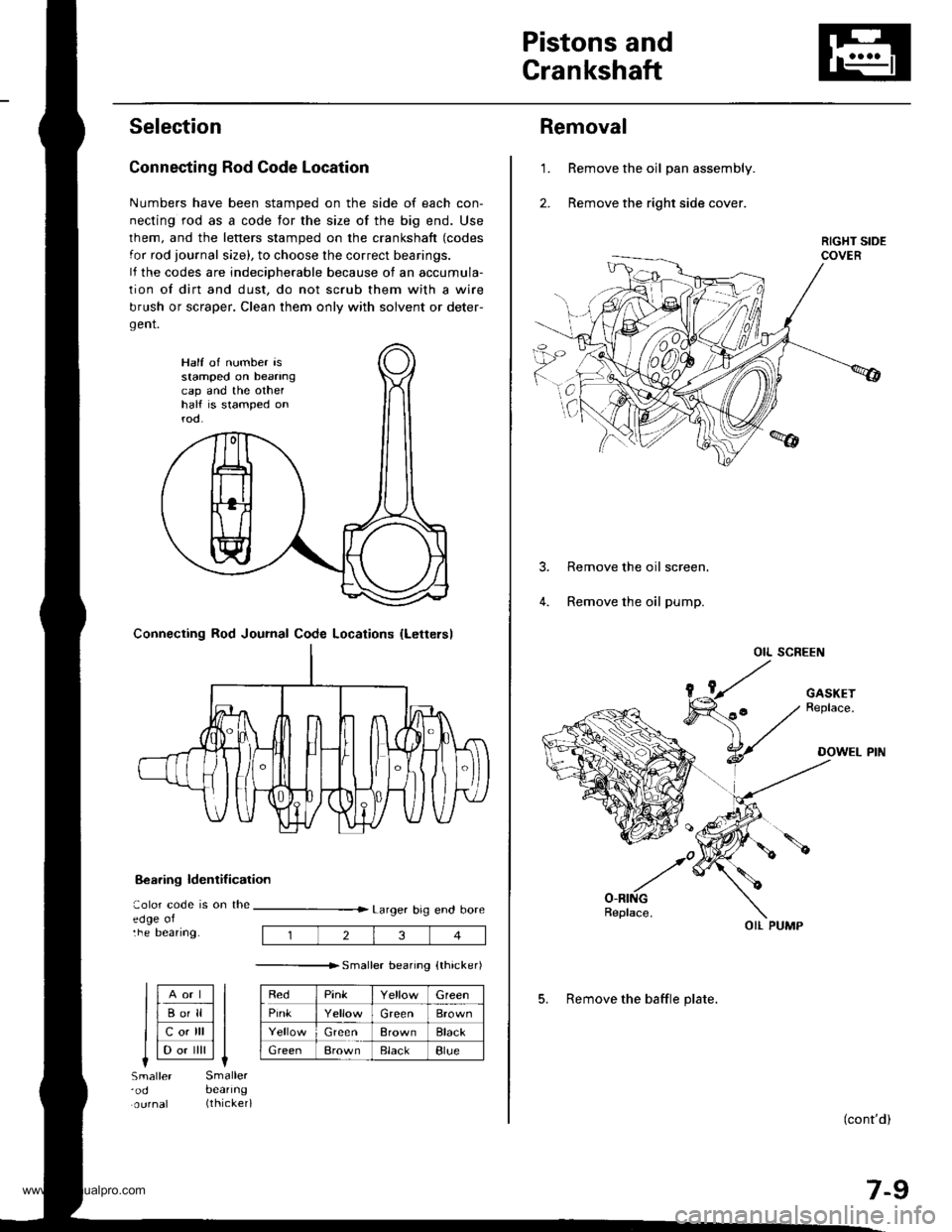
Connecting Rod Code Location
Numbers have been stamped on the side of each con-
necting rod as a code for the size of the big end. Use
lhem, and the letters stamped on the crankshaft (codes
for rod journal size), to choose the correct bearings.
lf the codes are indeciDherable because of an accumula-
tion of dirt and dust, do not scrub them with a wire
brush or scraper. Clean them only with solvent or deter-
gent.
8€aring ldentif ication
aolor code is on theedge oltne Deanng.
Larger big end bore
---------------r. sma er bearino {thicker)
RedPinkGreen
PinkGreenBrown
GreenBrownBlack
GreenBrownElackBlue
Half of number isstamped on beanngcap and the othelhalf is stamped onrod.
Connecting Rod Journal Code Locations {Lettersl
llAort ll
llBo'll ll
llcotrll ll
I l-.. ilril It-lSmaller'odSmallerbeanng(thicker)
234
Removal
Remove the oil pan assembly.
Remove the right side cover.
1.
Remove the oil screen.
Remove the oil pump.
OIL SCREEN
(cont'd)
7-9
OIL PUMP
5. Remove the baffle plate.
www.emanualpro.com
Page 485 of 1395
Transfer Assembly
Inspection
NOTE: To prevent damage to the transfer housing,
always use soft jaws or equivalent materials between
the transfer housing and the vise.
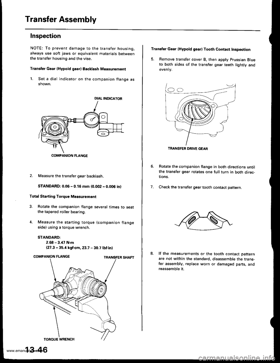
Transter Gaar (Hypoid goar) Backlssh M€asurement
1. Set a dial indicator on the companion flange asshown.
2. Measure the transfer gear backlash.
STANDARD: 0.06 - 0.16 mm {0.002 - 0.006 in}
Total Sta.ting Torquo Msasuremont
3. Rotate the companion flange several times to seatthe tapered roller bearing.
4. Measure the starting torque (companion flange
side) using a torque wrench.
STANDARD:
2.68 - 3.47 N.m
{27.3 - 35.4 kgf.cm.23.7 - 30.7 tbt.in)
DIAL INDICATOR
COMPANION FLANGE
13-46
Transfer Gear lHypoid gearl Tooth Contaqt Insp€ction
5. Remove transfer cover B, then apply Prussian Blueto both sides of the transler gear teeth lightly andevenlv.
Rotate the companion flange in both directions untilthe transfer gear rotates one full tuln in both direc-tions.
Check the transfer gear tooth contact pattern.7.
lf the measurements or the tooth contact Datternare not within the standard. disassemble the trans-fer assembly, replace worn or damaged parts, andreassemble it.
TRANSFER DRIVE GEAR
www.emanualpro.com
Page 495 of 1395
Transfer Assembly
Reassembly (cont'dl
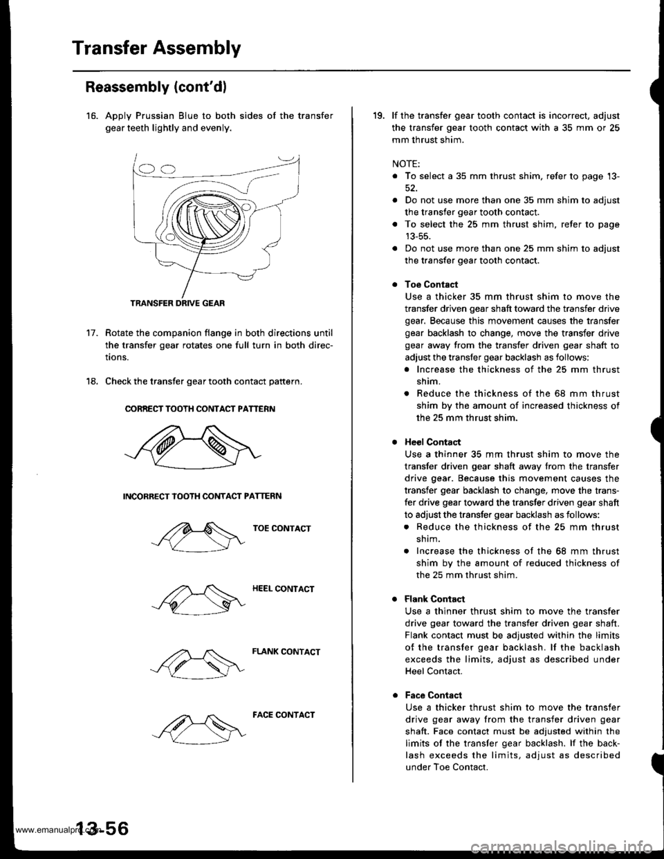
16. Apply Prussian Blue to both sides of the transfer
gear teeth lightly and evenly.
Rotate the companion flange in both directions until
the transfer gear rotates one full turn in both direc-
tions.
Check the transfer gear tooth contact pattern.
CORREST TOOTH CONTACT PATTERN
INCORRECT IOOTH CONTACT PATTERN
TOE CONTACT
HEEL CONTACT
FLANK CONTACT
17.
18.
TRANSFER DRIVE GEAR
13-56
FACE CONTACT
19. lf the transfer gear tooth contact is incorrect, adjust
the transfer gear tooth contact with a 35 mm or 25
mm thrust shim.
NOTE:
. To select a 35 mm thrust shim, refer to page '13-
. Do not use more than one 35 mm shim to adjust
the transfer gear tooth contact.
. To select the 25 mm thrust shim, refer to page
13-55.
a Do not use more than one 25 mm shim to adjust
the transfer gear tooth contact.
Toe Contact
Use a thicker 35 mm thrust shim to move the
transfer driven gear shaft toward the transfer drive
gear. Because this movement causes the transfer
gear backlash to change, move the transfer drive
gear away from the transfer driven gear shaft to
adjust the transfer gear backlash as iollows;
. Increase the thickness of the 25 mm thrust
shim.
. Reduce the thickness of the 68 mm thrust
shim bv the amount of increased thickness of
the 25 mm thrust shim.
Heol Contact
Use a thinner 35 mm thrust shim to move the
transfer driven gear shaft away from the transfer
drive gear. Because this movement causes the
transfer gear backlash to change, move the trans-
fer drive gear toward the transfer driven gear shaft
to adjust the transfer gear backlash as follows:
. Reduce the thickness of the 25 mm thrust
sh im.
a Increase the thickness of the 68 mm thrust
shim by the amount of reduced thickness of
the 25 mm thrust shim.
Flank Contact
Use a thinner thrust shim to move the transfer
drive gear toward the transfer driven gear shaft.
Flank contact must be adtusted within the limits
of the transfer gear backlash. lf the backlash
exceeds the limits, adjust as described under
Heel Contact.
Face Contsct
Use a thicker thrust shim to move the transfer
drive gear away from the transfer driven gear
shaft. Face contact must be adjusted within the
limits of the transjer gear backlash. lf the back-
lash exceeds the limits, adjust as described
under Toe Contact.
www.emanualpro.com
Page 750 of 1395
Transfer Assembly
Inspection
NOTE: To prevent damage to the transfer housing,
always use soft jaws or equivalent materials between
the transfer housing and the vise.
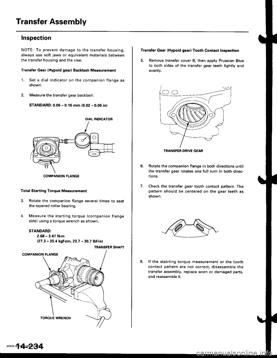
Trsnsfer Gear (Hypoid gear) Backl8sh M€asurem€nt
1. Set a dial indicator on the companion flange as
snown.
2. Measure the transfer gear backlash.
STANDARD: 0.06 - 0.16 mm {0.02 - 0.06 in)
Total Starting Torque Meagurgm€nt
3, Rotate the companion flange several times to seat
the tapered roller bearing.
4. Measure the starting torque (companion flange
side) using a torque wrench as shown,
STANDARD:
2.68 - 3.,17 N.m(27.3 - 35.,1 kgf.cm, 23.7 - 30.7 lbf.inl
TRANSFER SHAFT
DIAL INDICATOR
COMPANION FLANGE
14-234
Transfer Gear (Hypoid gear) Tooth Contact Inspection
5, Remove transfer cover B, then apply Prussian Blue
to both sides of the transfer gear teeth lightly and
Rotate the companion flange in both directions until
the transfer gear rotates one full turn in both direc-
tions.
Check the transfer gear tooth contact pattern. Thepattern should be centered on the gear tseth as
snown.
6.
7.
8.lf the statrting torque measurement or the tooth
contact pattern are not correct, disassemble the
transfer assembly, replace worn or damaged parts,
and reassemble it.
TRANSFER DRIVE G€AR
www.emanualpro.com
Page 760 of 1395
Transfer Assembly
18.
Reassembly (cont'dl
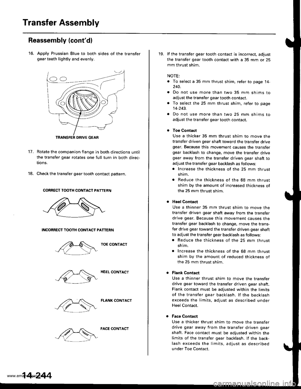
16. Apply Prussian Blue to both sides of the transfergear teeth lightly and evenly.
17.Rotate the companion flange in both directions until
the transfer gear rotates one full turn in both direc-
tions.
Check the transfer gear tooth contact pattern.
CORRECT TOOTH CONTACT PATTERN
NCONRECT TOOTH CONTACT PATTERN
TOE CONTACT
HEEL CONTACT
FLANK CONTACT
14-244
FACE CONTACT
19. lf the transfer gear tooth contact is incorrect, adjust
the transfer gear tooth contact with a 35 mm or 25
mm th rust shim.
NOTE:
. To select a 35 mm thrust shim, refer to page 14,240.
. Do not use more than two 35 mm shims to
adjust the transfer gear tooth contact.. To select the 25 mm thrust shim, refer to page
14-243.
. Do not use more than two 25 mm shims to
adjust the transfer gear tooth contact.
Toe Contact
Use a thicker 35 mm thrust shim to move the
transfer driven gear shaft toward the transfer drivegear. Because this movement causes the transfergear backlash to change, move the transfer drivegear away from the transfer driven gear shaft to
adjust the transfer gear backlash as follows:. Increase the thickness of the 25 mm thrust
shrm.
. Reduce the thickness of the 68 mm thrust
shim by the amount of increased thickness of
the 25 mm thrust shim.
Heel Contact
Use a thinner 35 mm thrust shim to move the
transfer driven gear shaft away from the transfer
drive gear. Because thjs movement causes the
transfer gear backlash to change, move the trans-
fer drive gear toward the transfer driven gear shaft
to adjust the transfer gear backlash as follows:. Reduce the thickness of the 25 mm thrust
shim.
. Increase the thickness of the 68 mm thrust
shim by the amount of reduced thickness ofthe 25 mm thrust shim.
Flank Contaqt
Use a thinner thrust shim to move the transfer
drive gear toward the transfer driven gear shaft.Flank contact must be adjusted within the limits
of the transfer gear backlash. lf the backlash
exceeds the limits, adjust as described underHeel Contact.
Face Contaqt
Use a thicker thrust shim to move the transfer
drive gear away from the transfer driven gear
shaft. Face contact must be adjusted within the
limits of the transfer gear backlash. lf the back-
lash exceeds the limits, adjust as described
under Toe Contact.
www.emanualpro.com
Page 1165 of 1395
Five-step Troubleshooting
1.
3.
Verify The Complaint
Turn on all the components in the problem circuit to
verify the customer complaint. Note the symptoms.
Do not begin disassembly or testing until you have
narrowed down the problem area.
Analyze The Schematic
Look up the schematic for the problem circuit.
Determine how the circuit is supposed to work by
tracing the current paths from the power feed
through the circuit components to ground. lf several
circuits fail at the same time, the fuse or ground is a
likely cause,
Based on the symptoms and your understanding of
the circuit operation, identify one or more possible
causes of the problem.
lsolate The Problem By Testing The Circuit
Make circuit tests to check the diagnosis you made
in step 2. Keep jn mind that a logical, simple proce-
dure is the key to efficient troubleshooting. Test for
the most likely cause of failure first. Try to make
tests at points that are easily accessible,
Fix The Problem
Once the specific problem is identified, make the
repair. Be sure to use proper tools and safe proce-
dures.
Make Sure The Circuit Works
Turn on all components in the repaired circuit in all
modes to make sure you've fixed the entire prob-
lem. lf the problem was a blown fuse, be sure to
test all of the circuits on the fuse. lvlake sure no new
problems turn up and the original problem does nol
recur.
4.
O
Wire Color Codes
The following abbreviations are used to identify wire
colors in the circuit schematics:
WHT ............................. White
YEL,.............................. Yellow
BLK ..........,................... Black
BLU .............................. Blue
GRN .............................Green
RED .............................. Red
ORN .............................Oran9e
PNK.....,........................ Pink
BRN .............................. Brown
GRY .............................. Gray
PUR .........,.................... Purple
LT BLU ..................,...... Light Blue
LT GRN ........................ Light Green
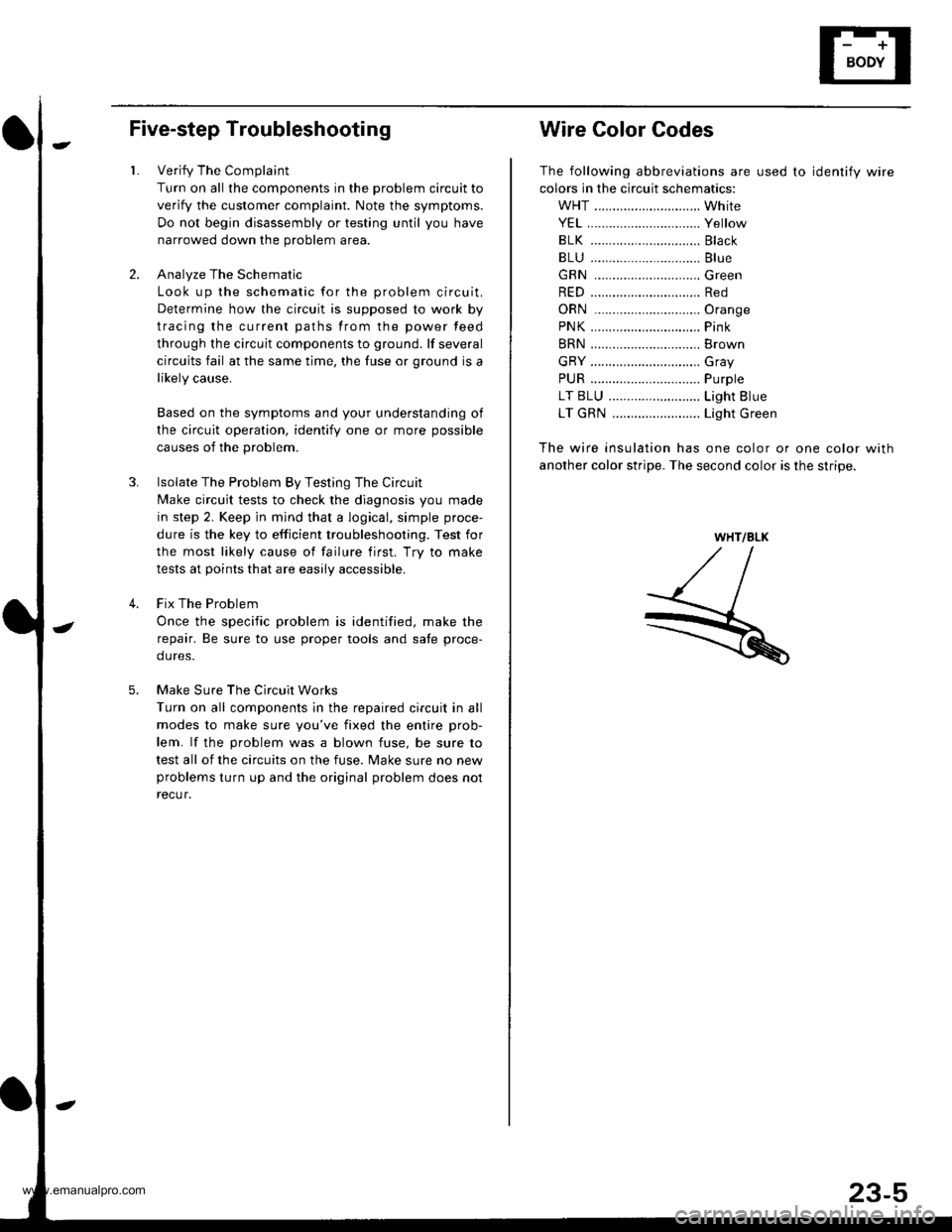
The wire insulation has one color or one color with
another color stripe. The second color is the stripe.
WHT/BLK
www.emanualpro.com