1999 HONDA CR-V Range sensor
[x] Cancel search: Range sensorPage 279 of 1395
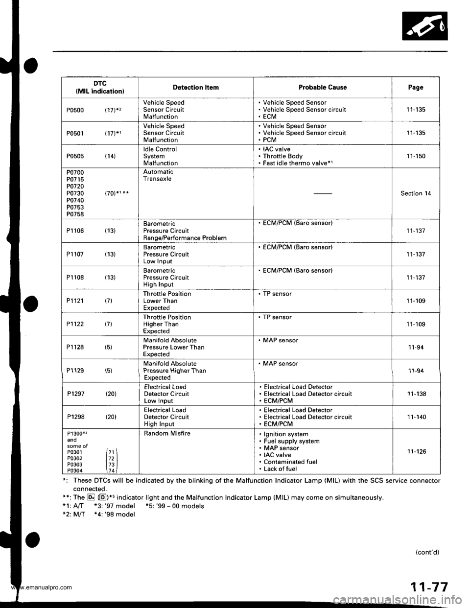
DTC(MlL indicationlDotection ltomProbable CausePage
P0500 t17)*,
Vehicle SpeedSensor CircuitMalfunction
Vehicle Speed SensorVehicle Speed Sensor circu itECtVI1 1-135
P0501 l17J*1
Vehicle SpeedSensor CircuitMalfunction
Vehicle Speed SensorVehicle Speed Sensor circuitPCM11-135
P0505 (14)ldle ControlSystemMalfunction
IAC valveThrottle BodyFast idle thermo valve*11 '�]- 150
P0700P0715PO720P0730P0740P0753P0758
AutomaticTransaxle
Section l4
P1106 (13)BarometricPressure CircuitRange/Performance Problem
ECM/PCM (Baro sensor)
11-137
P1107 (13)BarometricPressure CircuitLow InPut
. ECM/PCM {Baro sensor)11-137
P1108 (13)BarometricPressure CircuitHigh Inpur
ECM/PCM {Baro sensor)11,137
P1121 (7)Throttle PositionLower ThanExpected
. TP sensor11-109
P1122 (7)Throttle PositionHigher ThanExpected
' TP sensor1 1-'109
P112a (5)Manifold AbsolutePressure Lower ThanExpected
. MAP sensor11-94
P1129 (5)Manifold AbsolutePressure HiqherThanExpected
' MAP sensor1l-94
P1297 (20)Electrical LoadDetector CircuitLow Input
Electrical Load DetectorElectrical Load Detector circuitECM/PCM1 1- 138
P1298 (20)Electrical LoadDetector CircuitHigh Input
Electrical Load DetectorElectrical Load Detector circuitECM/PCM11-140
P1300'3
P0301P0302P0303P0304
7l721314
Random lvlisfirelgnition systemFuel supply systemMAP sensorIAC valveContaminated fuelLack offuel
11-126
*: These DTCS will be indicated by the blinking of the Malfunction Indicator Lamp {MlL} with the SCS service connector
connected.**:The E (E])+s indicator light and the Malfunction Indicator Lamp (MlL) may come on simultaneously.*1:A,./T "3: '97 model +5: '99 - 00 models*2: M/T *4:'98 model
{cont'd)
11-77
www.emanualpro.com
Page 301 of 1395
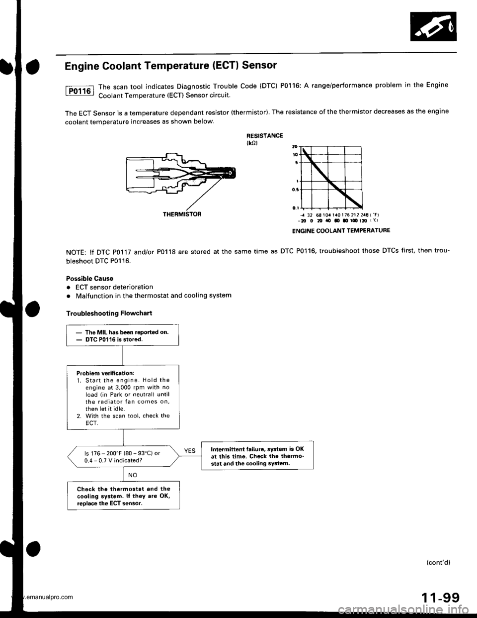
Engine Goolant Temperature (ECTI Sensor
The scan tool indicates Diagnostic Trouble Code (DTC) P0116: A range/performance problem in the Engine
Coolant Temperature (ECT) Sensor circuit.
The ECT Sensor is a temperature dependant resistor (thermistor). The resistance of the thermistor decreases as the engine
coolant temperature increases as shown below
RESISTANCEtk0l
NOTE: lf DTC P0117 and/or P0118 are stored at the same
bleshoot DTC P0116.
Possible Cause
a ECT sensor deterioration
. Malfunction in the thermostat and cooling system
Troubleshooting Flowchart
-4 32 68 r0a r a0176 212 2aE {'r)-2O O 20 ito tO .o ! t2O I c)
ENGINE COOLANT TEMPERATURE
time as DTC P0116, troubleshoot those DTCS first, then trou-
THERMISTON
- The MIL has be€n roported on.- DTC P01'16 is stored.
Probl6m verification:1. Start the engine. Hold theengine at 3,000 rpm with noload (in Park or neutral) untilthe radiator fan comes on,then let it idle.2. With the scan tool, check theECT.
Intermittent failure, sYstem b OKat this tim6. Check lhe thermo-stat and the cooling 5y3tom.
ls 176 - 200'F (80 - 93"C) or0.4-0.TVindicated?
Check the thermostat and the
cooling system. It th€y are OK,reolace the ECT seNor.
(cont'd)
1 1-99
www.emanualpro.com
Page 333 of 1395
tro-rsl
1Tffi61
tF136t
fPfa6r-1
tF138tl
I-Pi382l
Crankshaft Position/Top Dead Genter/Gylinder Position (CKP/TDC/CYPI Sensor
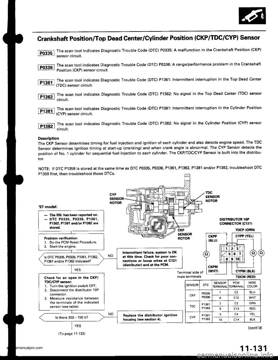
The scan tool indicates Diagnostic Trouble Code (DTC) P0335; A malfunction in the Crankshaft Position (CKP)
sensor circuit,
The scan tool indicates Diagnostic Trouble Code (DTC) P0336: A range/performance problem in the Crankshaft
Position {CKP) sensor circuit.
The scan tool indicates Diagnostic Trouble Code {DTC) P1361: Intermittent interruption in the Top Dead Center
(TDC) sensor circuit.
The scan tool indicates Diagnostic Trouble Code (DTC) P1362: No signal in the Top Dead Center (TDC) sensor
ci.cuit.
The scan tool indicates Diagnostic Trouble Code (DTC) P1381: Intermittent interruption in the Cylinder Position
(CYP) sensor circuit.
The scan toot indicates Diagnostic Trouble Code {DTC) P1382: No signal in the Cylinder Position (CYP} sensor
circuit.
Description
The CKP Sensor determines timing for fuel injection and ignition of each cylinder and also detects engine speed. The TDC
Sensor determines ignition timing at start-up {cranking) and when crank angle is abnormal. The CYP Sensor detects the
position of No. 't cylinder for sequential fuel injection to each cylinder. The CKP/TDC/CYP Sensor is built into the distribu-
ror.
NOTE: lf DTC P1359 is stored atthesametimeas DTC P0335, P0336, Pl361, P1362, P1381 and/or P1382, troubleshoot DTC
P1359 first, then troubleshoot those DTCS.
DISTRIBUTOR lOPCoNNECTOR (Cl211
TDCP IGRNI
Terminal side ofmale terminalsTIrcM IREOI
'97 model:
- The MIL has be€n reported on.- DTC P0335, P0336, P136'�1,P1362, Pl341 and/oi P1382 arestored.
Problem verific.tion:1. Do the PCM Reset Procedure.2. Start the engine.
Intermittent lailure, 3yd6m i3 OKat thb tims. Chcck tor poor con-nections ol looso wire3 si C12'l
ldistributor) .nd .t the PCM.
ls DTC P0335, P0336, P1361, P1362,P1381 and/or P1382 indicated?
Ch.ck for an open in tho CKP/TDC/CYP sensor:1. Turn the ignition switch OFF.2. Disconnect the distributor 10Pconnector.3. Measure resistance betweenthe terminals of the indicatedsensor (see table).
Replace tho distributor ignitionhousing {sea 3ection 41.ls there 350 - 700 o?
(To page 11-132)
CYPP IYELI
CYPM (BLKI
SENSOEDTCSENSOBPCMERMINAIWIRECOLOR
CKPP0335P0336
lc28LU
8c12
TDCP1361P1352
2GRN
9c13RED
CYPP'�I381P1342
3c4YEL't0c14BLK
{cont'd)
11-131
www.emanualpro.com
Page 337 of 1395
![HONDA CR-V 1999 RD1-RD3 / 1.G Workshop Manual
Vehicle Speed Sensor (VSSI
lPosoo-]-. |posol l-
97 modol:
The scan tool indicates Diagnostic Trouble Code {DTC} P0500*�or P0501*r: A range/perfor-
mance in the Vehicle Speed Sensor (VSS) circuit. HONDA CR-V 1999 RD1-RD3 / 1.G Workshop Manual
Vehicle Speed Sensor (VSSI
lPosoo-]-. |posol l-
97 modol:
The scan tool indicates Diagnostic Trouble Code {DTC} P0500*�or P0501*r: A range/perfor-
mance in the Vehicle Speed Sensor (VSS) circuit.](/manual-img/13/5778/w960_5778-336.png)
Vehicle Speed Sensor (VSSI
lPosoo-]-'. |posol l-'
'97 modol:
The scan tool indicates Diagnostic Trouble Code {DTC} P0500*'�or P0501*r: A range/perfor-
mance in the Vehicle Speed Sensor (VSS) circuit. * I ; A/T*2i Mfi
FCM CONNECTORS
A t32Pl
LG1(BRN/BLK)
NOTE: Do not use the engine to turn thofront wheels with th6 rear wheels on theground. The 4WD system will engage andthe vehicle will suddenlv Iurch forward.
Wire side ot female terminals
LGl
{BRN/BLKI
(cont'd)
11-135
The MIL hes boen roported on.DTC m501 is 3tor€d.
Problom verificetion:1. Test'drive the vohicle.2. Check the vehicle speed withthe scan tool,
lntormittent tailure, rystom b OKat thia timo. Chock tor poor con-nection3 or 10o3o wires rt C129lvss) .nd rr rhe Pcfr4,
ls the correct speed indicated?
Chock for an open in tho PiCM:1. Turn the ignition switch OFF.2. Block the rear wheels and setthe parking brake.3. Jack up the lront of the vehicleand support it with saletystands.4. Turn the ignition switch ON (ll).
5. Elock the right front wheel andslowly rotate the left trontwheel by hand.6. Measure voltage betweenPCM connector terminals C18and A9.
Substitulc a known-good PCMand .och6ck. It symptom/indicd.tion go.a away, .cplaco tho origi-nel FCM.
Doesthe voltage pulse 0 Vand 5 V or battery voltage?
Check for a .hort in the PCM:L Turn the ignition switch OFF.2. Disconnect the PCM con'nector C (31P).
3. Turn the ignition switch ON (ll).
4. Elock the right front wheeland slowly rotate the left front
5. Measure vohage between PCMconnector terminals C18 andA9.
Substituto e known-good PCMand rochock. f rymptom/indica-tion goos rwry, roplsc. tho origi-nalFCM.
Doesthe voltage pulse 0 Vand 5 V or battery voltage?
- Repair short in the wirebetween the PCM lC18l,cruise control unit, speodo-meter, and VSS,- Repair opon in the wirebetween the PCM {C181 .ndrhe vss.- f wire is OK. tost lho VSS l3oosoction 231.
www.emanualpro.com
Page 339 of 1395
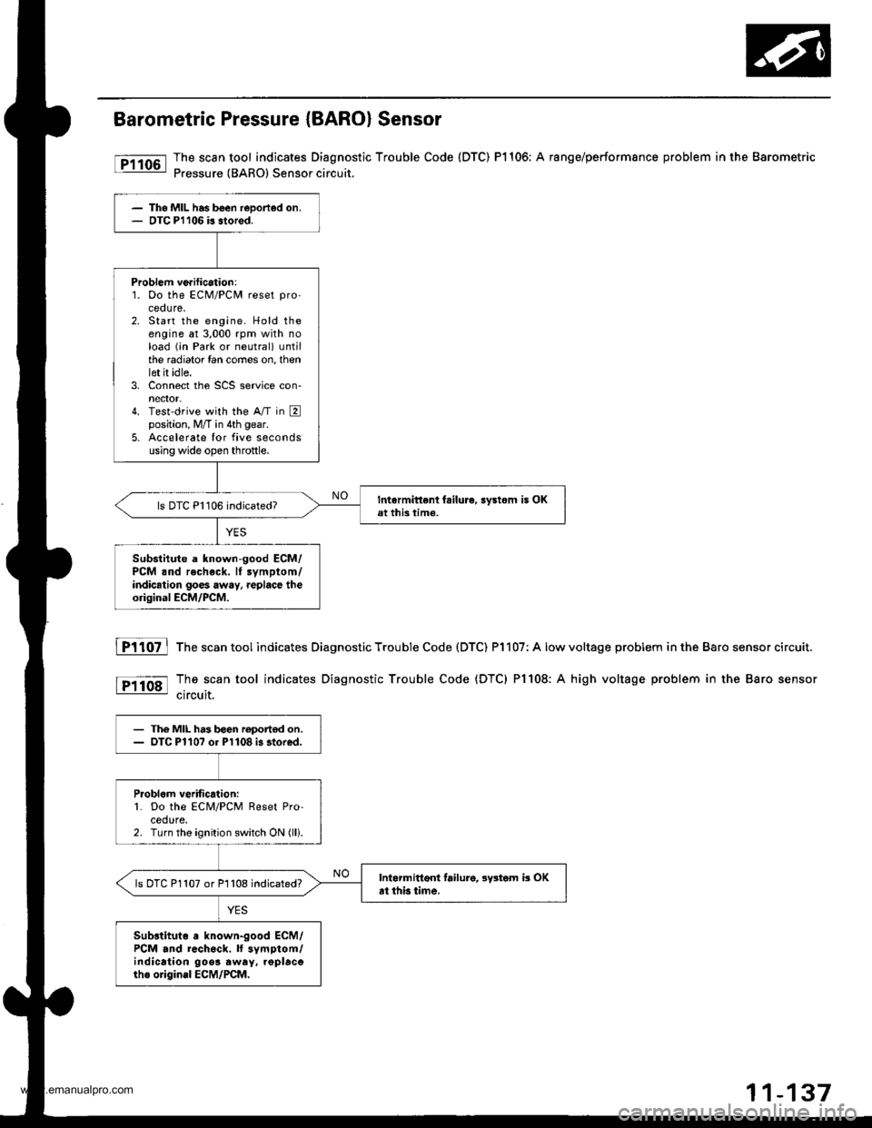
Barometric Pressure (BARO) Sensor
The scan tool indicates Diagnostic Trouble Code (DTC) P1106: A range/performsnce problem in the Barometric
Pressure {BARO) Sensor circuit.
The MIL has been reDorted on.OTC Pl106 b slored.
Problem ve.ification:1. Oo the ECM/PCM reset pro'
ceoure.2. Start the engine. Hold theengine at 3,000 rpm with noload (;n Park or neutral) untilthe radiator lan comes on, thenlet it idle.3. Connect the SCS service con-nector,4. Test'drive with the A/T in Eposition, M/T in 4th gear.
5. Accelerate Ior five secondsusing wide open throttle.
Intermittent fsilure, sy3tom i5 OKat this time.ls DTC P1106 indicated?
Substitute a known-good ECM/PCM .nd recheck. It symptom/indication goes away, replace theorigioal ECM/PCM.
fTiloz l
tP11o8l
The scan tool indicates Diagnostic Trouble Code (DTC) P1107: A low
The scan tool indicates Diagnostic Trouble Code (DTC) Pl108: A
circuit.
voltage problem in the Baro sensor circuit.
high voltage problem in the Baro sensor
- The MIL h.3 b€en roport€d on.- OTC Pl10? or Pl108 i3 stored.
Problom veritic.lion:L Do the ECM/PCM Reset Pro-cedure.2. Turn the ignition switch ON (lli.
Intarmittoni failure, lystom b OKat thb time.ls DTC P1107 or P1108 indicated?
Sub3tituto a known-good ECM/PCM and rcch6ck. ll symptom/indication 9oo3 away. .oplacorho o.igin.l ECM/PCM.
www.emanualpro.com
Page 410 of 1395
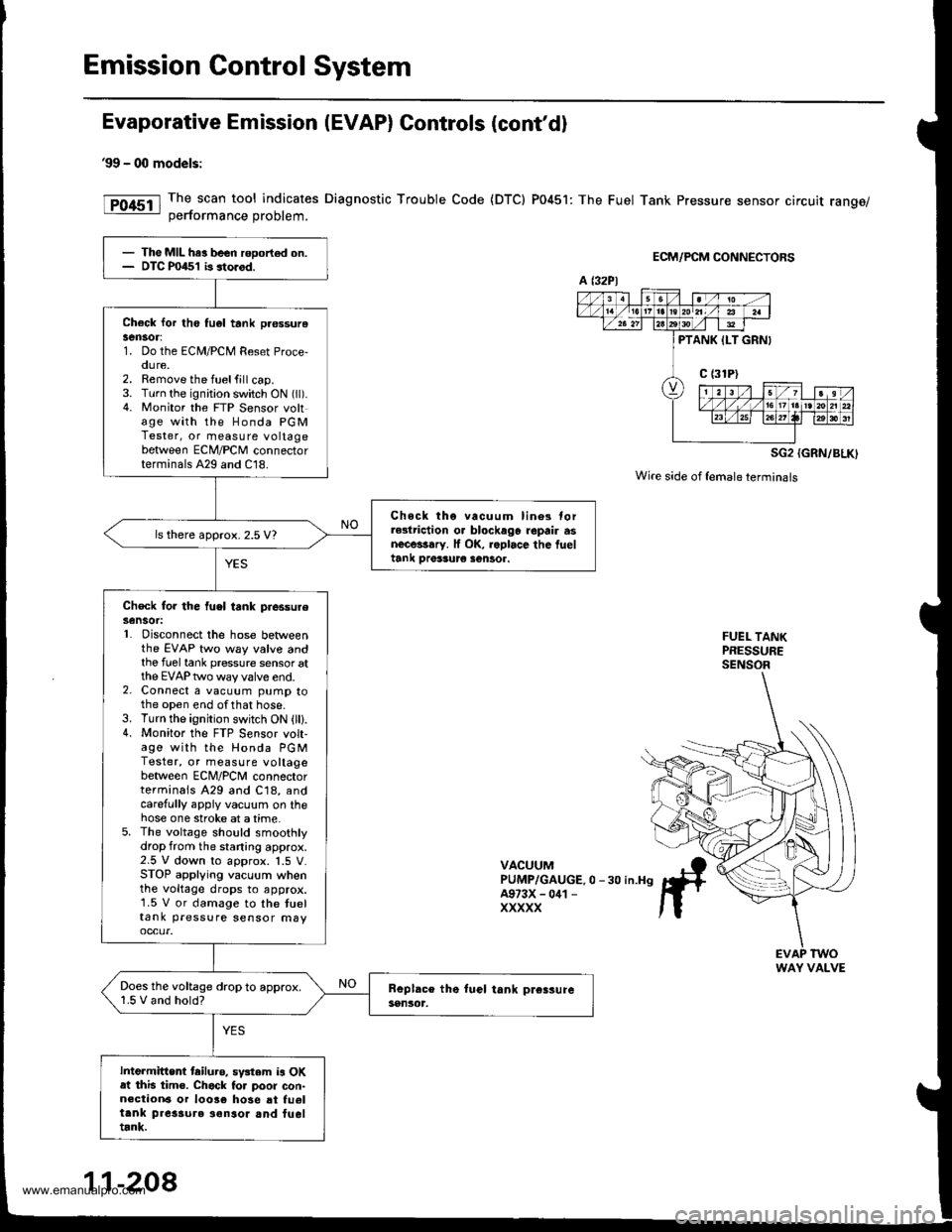
Emission Control System
Evaporative Emission (EVAP) Controls (cont'd)
99 - 00 models:
The scan tool indicates Diagnostic Trouble Code {DTC) P0451: The Fuel Tank Pressure sensor circuit range/oerformance Droblem.
ECM/PCM CONNECTORS
SG2 {GRN/BLK)
Wire side of {emaleterminals
FUEL TANKPRESSURESENSOR
VACUUMPUMP/GAUGE.0 -30 in.H9A973X - 041 -
XXXXX
- The MIL har been rooort€d on.- DTC P0451 b storod.
Check lor th6 tu6l tank pr€ssurelen30r:1. Do the ECM/PCM Reset Proce,oure.2. Remove the fuelfill cap.3. Turn the ignition switch ON (ll).4. Monitor the FTP Sensor voltage with the Honda PGMTester, or measure voltagebetween ECM/PCM connectorterminals A29 and C18.
Chock tho vacuum lin6s torrGlriction o. blockago repair asnecessary. lf OK, roplace the fueltank Drer3ur€ sentor.
ls there approx. 2.5 V?
Check for the fuel tank piessureSensot:L Disconnect the hose betweenthe EVAP two way valve andthe fuel tank pressure sensor atthe EVAP two way valve end.2. Connect a vacuum pump tothe open end ofthat hose.3. Turn the ignition switch ON (lll.4. Monitor the FTP S€nsor volt-age with the Honda PGMTester, or measure voltagebetween ECNI/PCNI connectorterminals A29 and C18, andcarefully appiy vacuum on thehose one stroke at a time.5. The voltage should smoothlydrop from the staning approx.2.5 V down to approx. 1.5 V.STOP applying vacuum whenthe voltage drops to approx.1.5 V or damage to the tueltank pressure sensor may
Does the voltage drop to approx.1.5 V and hold?
Intermittent tailuro. sv3tem is OKat this tim€. Chack to. poor con-n€ction6 or 10036 hose at fu6ltank pres3ure ionsor and fueltrnk.
a t32Pl
PTANK ILT GRNI
WAY VALVE
11-208
www.emanualpro.com
Page 519 of 1395

Description
General Operation
The Automatic transmission is a 3-element torque converter and triple-shaft electronically controlled unit which provides 4
speeds forward and 1 reverse speed The unit is positioned in line with the engine'
There are two tvoes of automatic transmission on CR-V; the four-wheel drive (4WD) model ('97 - 00)' and the front-wheel
drive (2WD) model ('98 - 00).
Toroue Converter, G€ars, and Clutches
The torque converter consists of a pump. turbine. and stator assembly in a single unit. The torque converter is connected to
the engine crankshatt. These parts turn together as a unit as the engine turns. Around the outside of the torque converter is
a ring gear which meshes with the starter pinion when the engine is started. The torque converter assembly serves as a fly-
wheel while transmitting power to the transmission mainshaft.
The transmission has three parallel shafts: the mainshaft. the countershaft, and the sub-shaft. The mainshaft is in line with
the engine crankshaft. The mainshaft includes the 1st, 2nd. and 4th clutches, and gears lor 3rd,2nd,4th. reverse and 1st
(3rd gear is integral with the mainshaft, while reverse gear is integral with the 4th gear). The countershaft includes the 3rd
clutch and gears for 3rd,2nd, 4th, reverse, 1st, and park. Reverse and 4th gears can be locked to the countershaft at its cen-
ter, providing 4th gear or reverse, depending on which way the selector is moved. The sub-shaft includes the lst-hold
clutch and gears for lst and 4th.
The gears on the mainshaft are in constant mesh with those on the countershaft and sub-shaft. When certain combinations
of gears are engaged by the ctutches, power is transmitted from the mainshaft to the countershaft to provide E, D!, tr, tr,
and E position ('97 - 98 models). and E. E, E, and E position ('99 - 00 models)'
Electlonic Control
The electronic controt system consists of the Powenrain Control Module (PCM), sensors, a linear solenoid, and four
solenoid valves. Shifting and lock-up are electronically controlled for comfortable driving under all conditions. The PCM is
located below the dashboard, under the kick panel on the passenger's side.
Hydraulic Control
The valve bodies include the main valve body, the secondary valve body, the regulator valve body, the servo body, and
the lock up valve body. They are bolted to the torque converter housing. The main valve body contains the manual valve,
the 1-2 shift valve, the 2nd orifice control valve. the CPB {Clutch Pressure Back-up) valve, the modulator valve, the servo
control valve. the relief valve, and ATF pump gears. The secondary valve body contains the 2-3 shift valve, the 3-4 shift
valve, the 3,4 orifice control valve. the 4th exhaust valve and the CPC (Clutch Pressure Control) valve. The regulator valve
bodv contains the pressure regulator valve, the torque converter check valve, the cooler relief valve, and the lock-up con-
trol valve. The servo body contains the servo valve which is integrated with the reverse shift tork, and the accumulators
The lock-up valve body contains the lock-up shift valve and the lock-up timing valve. The linear solenoid and the shift con-
trol solenoid valve Ay'B are bolted to the outside of the transmission housing, and the lock-up control solenoid valve Ay'B is
bolted to the outside of the torque converter housing. Fluid trom the regulator passes through the manual valve to the
various control valves. The clutches receive fluid from their respective feed pipes or internal hydraulic circuit
ShiftControl Mechanism
input from various sensors located throughout the vehicle determines which shift control solenoid valve the PCM will acti-
vate. Activating a shift control solenoid valve changes modulator pressure, causing a shift valve to move. This pressurizes
a line to one of the clutches. engaging that clutch and its corresponding gear. The shift control solenoid valves A and B are
controlled by the PCM.
Lock-up Mechanism
tn E! position (,97 - 98 modets) and in E position ('99 - O0 models), in 3rd and 4th, and in Del position in 3rd ('97 - 98
models) and in El position with Over,Drive (O/D) is OFF (by pressing rhe O/D switchl in 3rd ('99 - 00 models), pressurized
fluid is drained from the back of the torque converter through a fluid passage, causing the lock-up piston to be held
against the torque converter cover, As this takes place, the mainshaft rotates at the same speed as the engine crankshaft.
Together with hydraulic control, the PcM optimizes the timing of the lock-up mechanism The lock-up valves control the
range of lock-up according to lock-up control solenoid valves A and B, and the linear solenoid. When lock-up control
solenoid valves A and B activate, the modulator pressure changes. The lock-up control solenoid valves A and B and the
linear solenoid are controlled by the PCM.
{cont'd)
14-3
www.emanualpro.com
Page 948 of 1395

Anti-lock Brake System (ABSI,'97 - 00 Models
Special Tools ............. 19-26
Component Locations ......................... 19-27
Anti-lock Brake System (ABS)
Features/Construction ............. ......, 19-2A
Circuit Diagram ......... 19-32
ABS Control Unit Terminal
Arrangement ......... 19-34
Troubleshooting Precautions ............. 19-36
Diagnostic Trouble Gode (DTC)
Diagnostic Trouble Code (DTC)
Indication (SCS Model ................ 19-38
DTG Erasure (MES Mode) ............... 19-39
Troubleshooting lndex .................... 19-40
Troubleshooting
ABS Indicator Light Does Not
Come On ............ 19-41
ABS Indicator Light Does Not
Go Off (No DTC) ........................... 19-43
DTC 1r - 18:
Wheel Sensor .... 19-45
DTC 31 - 38:
Solenoid ............. 19-47
DTC 51 - 53:
ABS Pump Motor ......................... 19-49
DTC 54:
Main Relay ......... 19-52
DTC 61:
lgnition Voltage ........................... 19-54
DTC 81:
Central Processing Unit (CPU) .... 19-55
Modulator Unit
Removal/lnstallation ....................... 19-56
ABS Control Unit
Replacement ..,...... 19-57
Pulsers/Wheel Sensors
Inspection .............. 19-57
Wheel Sensor Replacement ............ 19-58
www.emanualpro.com