1999 HONDA CR-V Light relay
[x] Cancel search: Light relayPage 343 of 1395
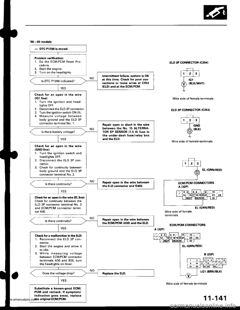
38 - 00 modeb:
Problem verification:1. Do the ECM/PCM Reset Proceoure.2. Stan the engine.3- Turn on the headlights.Intermittent feilure, sysl.m is OKat this time. Check for ooor con-nections or loose wires at C354(ELDI and at the ECM/PCM.
ls DTC P1298 indicated?
Check lor an open in the wire(lG1 line):'1. Turn the ignition and head-lights OFF.2. Disconnect the ELD 3P connector.3. Turn the ignition switch ON (ll).
4, Measu re voltage betweenbody ground and the ELD 3Pconnector terminal No. '1.Reprir open or short in th6 wirebotweon the No. 15 ALTERNA-TOR SP SENSOR {7.5 Al fuse inthe under-drah fuse/relay boxand the ELD.
Check tor an opon in tho wire{GND line}:1. Turn the ignition switch andheadlights OFF.2. Disconnect the ELD 3P connector.3. Check for continuity betweenbody ground and the ELD 3Pconnector terminal No. 2,
Repair opon in the wire betweenthe ELD conneclor and GilO2.
Ched( fo. an op€n in the wir€ (EL linel:Check for continuity between theELD 3P connector terminal No. 3and ECM/PCM connector termi-nalA30.
Repair op€n in tha wile botwecnthe EcM/PCM lA30l .nd rhe ELD.
Check for s malfunction in lhe ELD:1. Reconnect the ELD 3P con-nector.2. Start the engine and allow itto idle.3. While measuring voltagebetween ECM/PCM connectorterminals A30 and 820, turnthe headlights on (low).
Substiiute a known-good ECM/PCM and recheck. It symptom/indication goos away, replacethe original ECM/PCM.
ELO 3P CONNECTOR {c35/rl
Wire side of female terminals
Wire side of female terminals
Wire side ot temale terminals
ELD 3P CONNECTOR {C35,lt
EL IGRN/RED}Wire side of femaletermrnars
ECM/PCM CONNECTORS
A l32P)
11-141
www.emanualpro.com
Page 368 of 1395
ldle Control System
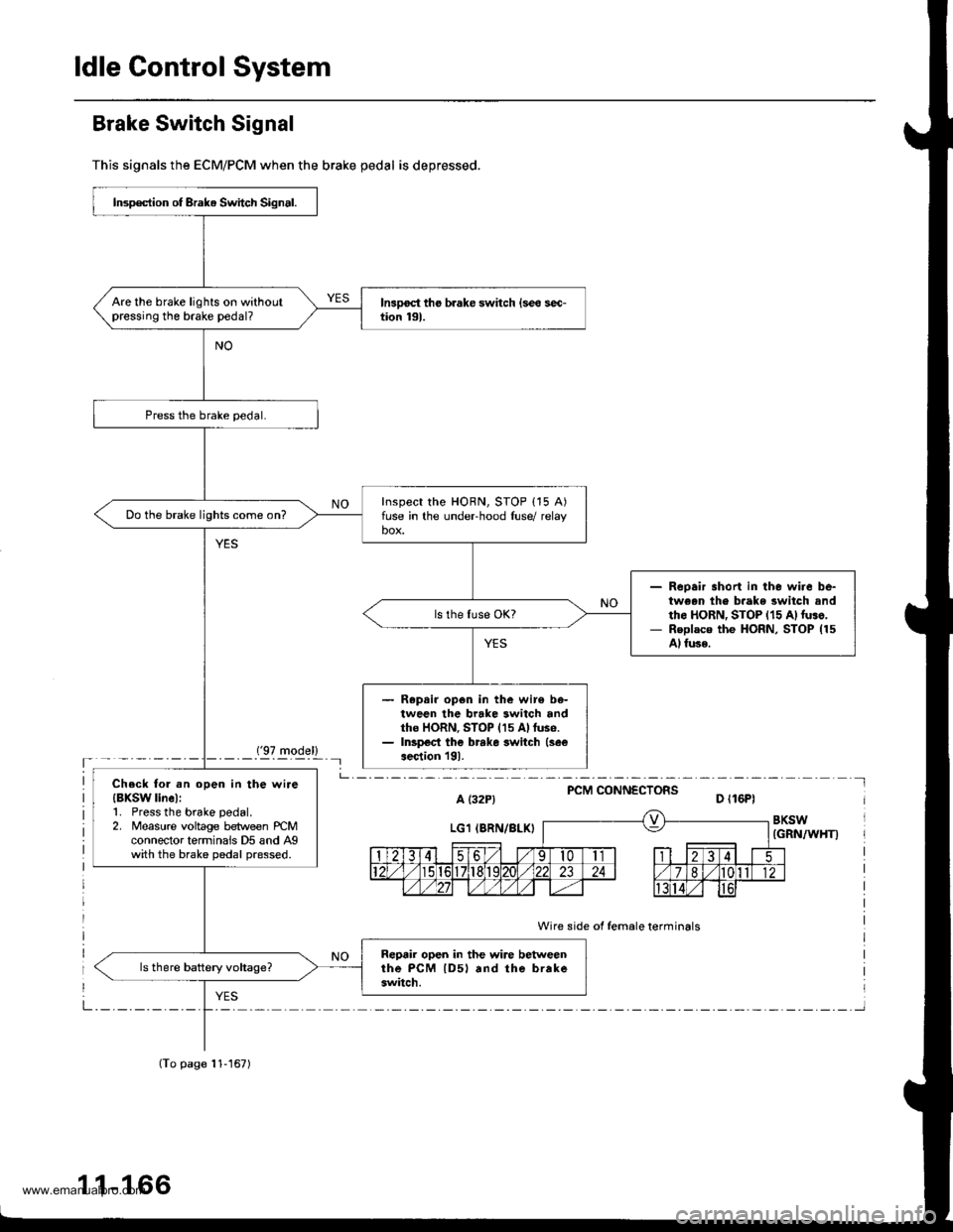
Brake Switch Signal
This signals the ECM/PCM when the brake pedal is depressed.
('97 model)'- - - - -_- Il
PCM CONNECTORSa t32P) D ll6Pl
BKSW(GRN/WHT)
Wire side of female terminals
Insp€ction of Brak. Switch Signal.
Are the brake lights on withoutpressing the brake pedal?
Inspect the HORN, STOP {15 A)fuse in the undeFhood luse/ relaybox.Do the brake lights come on?
Reoair short in the wire be-tween th€ b.ake switch andth6 HoRN, STOP {15 A)luso,Replaco the HoRN, STOP (15
Al fuse.
Repair op6n in the wir€ be-tween the brake switch andtho HORN, STOP (15 Allus6.Inspect the brrke switch (see
aection l9l.
Check tol .n open in the wire{BXSW linel:1. Press the brake pedal.2. Measure voltage between rcMconnector terminais D5 and Agwith the brake pedal pressed.
Reprir open in the wire betweenthe PcM lD5l rnd the brakeswitch.
(To page 11-167)
1 1-166
www.emanualpro.com
Page 388 of 1395
Fuel Supply System
Low Fuel Indicator System
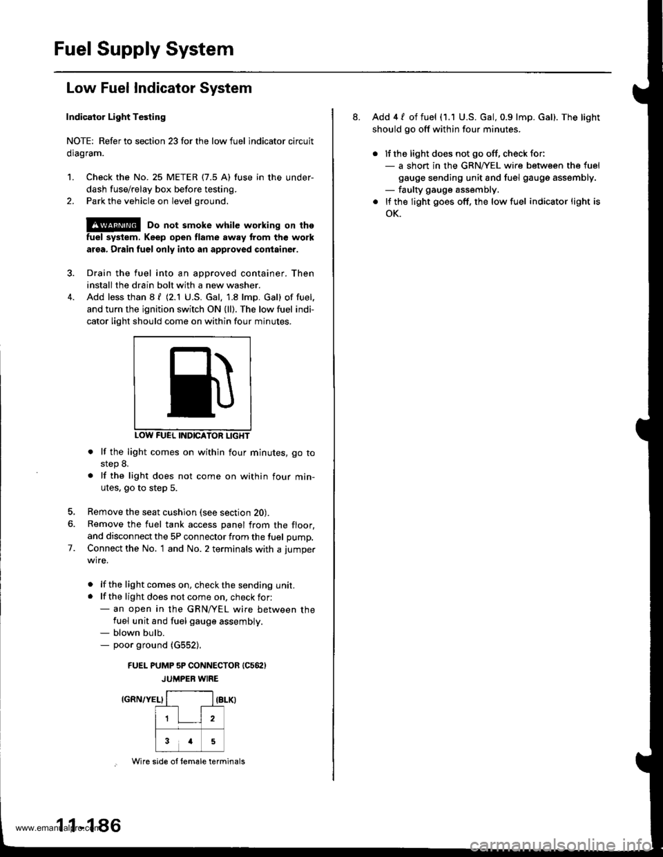
Indicator Light Testing
NOTE: Refer to section 23forthe lowfuel lndicator circuit
clragram.
1. Check the No. 25 METER (7.5 A) fuse in the under-
dash fuse/relay box before testing.
2. Park the vehicle on level ground.
@ Do not smoke while working on the
fuel system. Keep open flame away trom the work
aroa. Drain fuel only into an approved container.
Drain the fuel into an aoDroved container. Then
install the drain bolt with a new washer.
Add less than 8 f (2.1 U.S. Gal. 1.8 lmp. Gal) of fuel,
and turn the ignition switch ON {ll). The low fuel indi-
cator light should come on within four minutes.
INDICATON LIGHT
. lf the light comes on within four minutes, go tostep 8.
. lf the light does not come on within four min-
utes. go to step 5.
Remove the seat cushion (see section 20).
Remove the fuel tank access panel from the floor,
and disconnect the 5P connector from the fuel pump,
Connect the No. 1 and No. 2 terminals with a jumper
wire.
. lf the lightcomeson, checkthe sending unit.. lf the light does not come on, check for:- an open in the GRN/yEL wire between thefuel unit and fuel gauge assembly.- blown bulb.- poor ground (G552).
FUEI- PUMP 5P CONNECTOR (C562)
JUMPER WIRE
IGRN/YEL}
7.
1 1-1 86
Wire sid€ ol tem€le terminals
8. Add 4 / of fuel (1.1 U.S. Gal, 0.9 lmp. Gal). The light
should go off within four minutes.
. lJ the light does not go off, check for:- a short in the GRNA/EL wire between the fuel
gauge sending unit and fuel gauge assembly.- faulty gauge assembly.
. lf the light goes off, the low fuel indicator light is
oK.
www.emanualpro.com
Page 570 of 1395

PCM Terminal Voltage/Measuring Conditions
A/T Control System -'98 - 00 Models
The PCM terminal voltage and measuring conditions are shown for the connector terminals that are related to the A"/T con-
trol system. The other PCM terminal voltage and measuring conditions are described in section 11.
FCM Connector Terminal Localions
NOTE: 819 and C3 terminalsare applied to'99 - 00 models.
o (16Pt
T6rminal NumberSignalDescriptionMeasuring Conditions/Terminal Voltage
A5CRSDownshift signal input from
cruise control unit
When cruise control is used; Pulsing signal
A10scsTiming and adjustment service
check signal (5 V from PCM)
With ignition switch ON (ll) and service check
connector open:5 V
With ignition switch ON (ll) and service check
connector jumped with special tool: 0 V
A14('98 model)
D4 INDD4 indicator light control
{Voltage from PCM turns D4 light
oN)
When ignition switch is first turned ON (ll):
Battery voltage for two seconds
In E position: Battery voltage
A14
('99 - 00 models)
D INDD indicator light control(Voltage from PCM turns D light
oN)
When ignition switch is first turned ON (ll):
Baftery voltage for two seconds
ln E position: Battery voltage
428ILUInterlock control(Voltage from PCM)
When ignition switch ON {ll), brake pedal
depressed, and accelerator pedal released:
Battery voltage
A.32STOP SWBrake switch signal inputBrake pedal pressed; Battery voltage
Brake pedal released: 0 V
FCM CONNECTOR B I25P}
Terminal NumberSignalDescriptionMeasuring Conditions/Terminal Voltage
B1IGPlPower supply circuit from main
relay via under-hood Fuse 44
With ignition switch ON {ll): Battery voltage
With ignition switch OFF: 0 V
82PG1Ground (G101)
B8LSMLinear solenoid power supply
negative electrode
IG P2Power supply circuit from main
relay
With ignition switch ON (ll): Baftery voltage
With ignition switch OFF: 0 V
810PG2Ground (G101)
B17Linear solenoid power supply
positive electrode
With ignition switch ON (ll): Pulsing signal
819
('99 - 00 models)
O/D INDOver-Drive (O/D) OFF indicator
light control
When ignition switch is first turned ON (ll):
0 V for two seconds
O/D OFF indicator light ON:0 V
O/D OFF indicator light OFF: Battery voltage
s20Ground (G101)
B�21VBUBack-up power supply(under-hood Fuse 47)
Always battery voltage
B�22LG2Ground (G101)
14-54
www.emanualpro.com
Page 572 of 1395
Troubleshooting Procedures
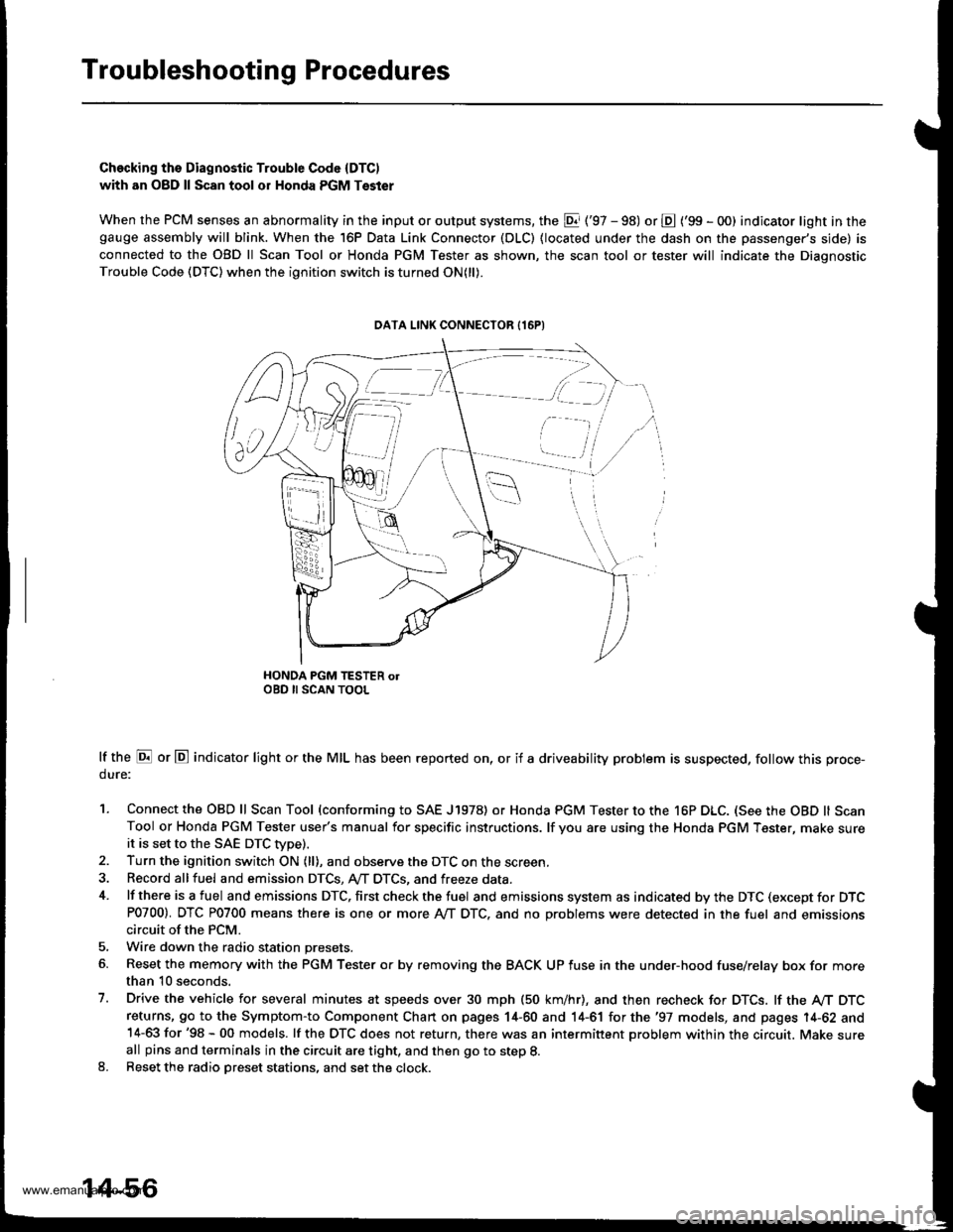
Checking ths Diagnostic Trouble Code (DTC)
with an O8D ll Scan tool or Honda PGM Tsster
When the PCM senses an abnormality in the input or output systems, the El ('97 - 98) or E ('99 - O0) indicator light in thegauge ass€mbly will blink. When the 16P Data Link Connector (DLC) {located under the dash on the passenger's side) is
connected to the OBD ll Scan Tool or Honda PGM Tester as shown, the scan tool or tester will indicate the Diagnostic
Trouble Code (DTC) when the ignition switch is turned ON(ll).
HONDA PGM TESTER olOBD II SCAN TOOL
lf the E or E indicator light or the MIL has been reported on, or if a driveability problem is suspected, follow this proce-
dure:
1. Connect the OBD ll Scan Tool (conforming to SAE J1978) or Honda PGM Tester to the 16P DLC. (See the OBD ll ScanTool or Honda PGM Tester user's manual for specific instructions. lf you are using the Honda PGM Tester, make sureit is set to the SAE DTC Wpe).2. Turn the ignition switch ON (ll), and observe the DTC on the screen
3. Record allfuel and emission DTCS, A,,/T DTCS, and freeze data.
4. lf there is a fuel and emissions DTC, first check the fuel and emissions system as indicated by the DTC (except for DTCP0700). DTC P0700 means there is one or more Ay'T DTC, and no Droblems were detected in the fuel and emissionscircuit of the PCM.
5. Wire down the radio station presets.
6. Reset the memory with the PGM Tester o. by removing the BACK UP fuse in the under-hood fuse/relay box for morethan 10 seconds.
7. Drive the vehicle for several minutes at speeds over 30 mph (50 km/hr), and then recheck for DTCS. lf the A/T DTCreturns, 9o to the Symptom-to Component Chart on pages 14-60 and 14-61 for the '97 models, and pages 14-62 and14-63 for '98 - 00 models. lf the OTC does not return, there was an intermittent problem within the circuit. Make sureall pins and terminals in the circuit are tight, and then go to step 8.8. Reset the radio Dreset stations, and set the clock.
DATA LINK CONNECTOR {16PI
[ -=.r,
ili,i /i,
v,., i
14-56
www.emanualpro.com
Page 599 of 1395
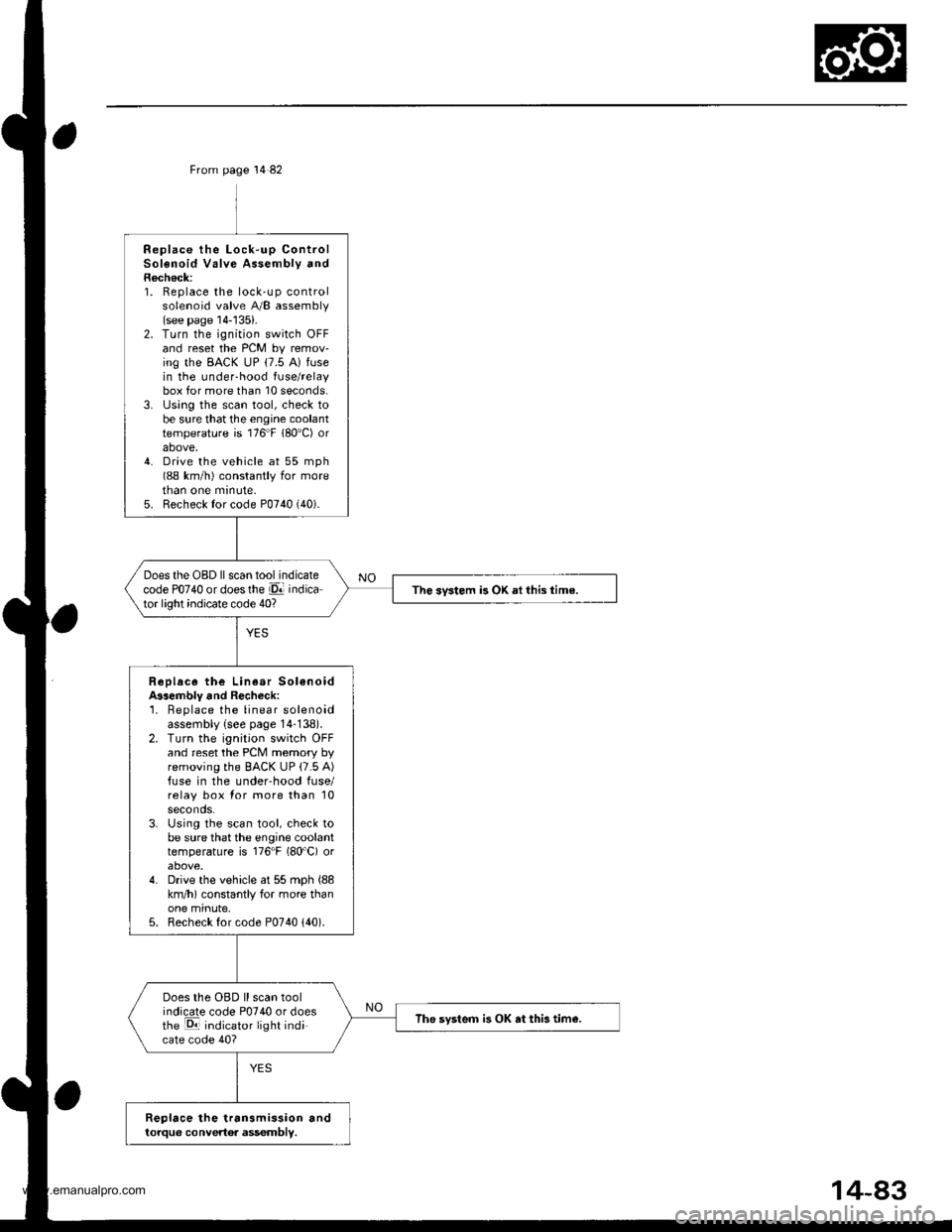
From page 14 82
Replace the Lock-up ControlSolenoid Valve Assembly andRecheck:1. Replace the lock-up controlsolenoid valve A/B assembly(see page 14-'135).2. Turn the ignition switch OFFand reset the PCM by remov-ing the BACK uP (7.5 A) fusein the under-hood fuse/relaybox for more than 10 seconds.3. lJsing the scan tool, check tobe sure that the engine coolanttemperature is 176"F 180'C) orabove,4. Drive the vehicle at 55 mph(88 km/h) constantly for moretnan one mrnute.5. Recheck for code P0740 (40).
Does the OBD ll scan tool indicatecode PO74O or doesthe El indicator light indicate code 40?The svstem is OK ai this time.
Replace the Linear Sol€noidA$embly and Recheck:'1. Beplace the linear solenoidassembly {see page 14-138).2. Turn the ignition switch OFFand reset the PCM memory byremoving the BACK UP (7.5 A)fuse in the underhood fuse/relay box for more than 10seconds.3. Using the scan tool, check tobe sure that the engine coolanttemperature is 176"F (80'C) orabove.4. Drive the vehicle at 55 mph (88
km/h) constantly for more thanone minute,5. Recheck for code P0740 {40).
Does the OBD ll scan toolindicate code P0740 or doesthe E indicator light indicate code 40?
The svsteo is OK at this tim€.
Replace the transmission andtorque convertor assembly.
www.emanualpro.com
Page 601 of 1395
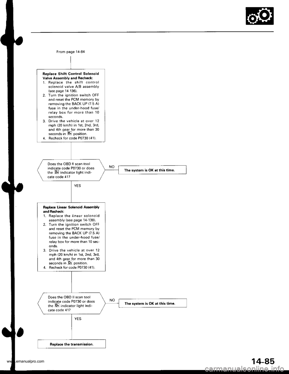
Replace Shift Control Solenoidvslve Assembly and Recheck:1. Replace the shift controlsolenoid valve A/B assembly(see page'14 136).2. Turn the ignition switch OFFand reset the PCM memory byremoving the BACK UP (7.5 A)fuse in the under-hood fuse/relay box for more than 10seconds.3. Drive the vehicle at over 12mph (20 km/h) in 1st,2nd,3rd,and 4th qear for more than 30seconds in E position.
4. Recheck for code P0730 (41).
Does the OBD ll scan toolindicate code P0730 or doesthe E indicator light indicate code 41?
The svstem is OK at this time.
Replace Linea. Solenoid Ass€mblyand Recheck:1. Replace the linear solenoidassembly lsee page 14-138).2. Turn the ignition switch OFFand reset the PcM memory byremoving the BACK UP 17.5 A)fuse in the underhood fuse/relay box tor more than 10 sec'onos.3. Drive the vehicle at over '12
mph {20 km/h) in 1st,2nd,3rd,and 4th geal for more than 30seconds in -Da position.
4. Recheck for code P0730 (41).
Does the OBD llscan toolindicate code P0730 or doesthe Di indicator light indi-cate code 41?
The syslem is OK at this time.
From page 14-84
14-85
www.emanualpro.com
Page 636 of 1395
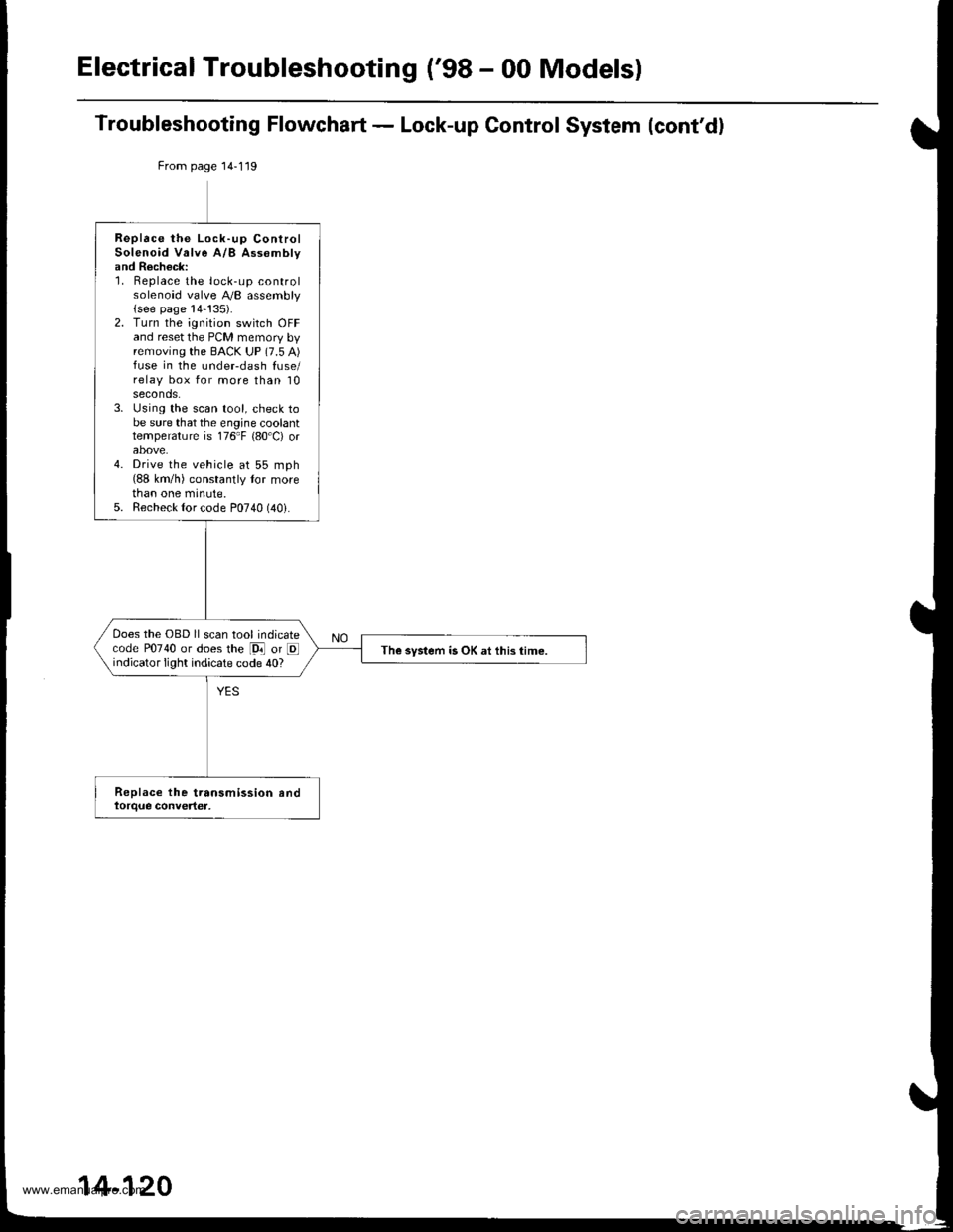
Electrical Troubleshooting ('98 - 00 Models)
Troubleshooting Flowchart - Lock-up Control System (cont'd)
From page 14-119
Replace the Lock-up ControlSolenoid Valve A/B Assomblyand Recheck:1. Replace the lock-up controlsolenoid valve A,/B assembly(see page 14-!35).2. Turn the ignition switch OFFand reset the PCM memory byremoving the BACK UP (7.5 A)fuse in the undeFdash fuse/relay box for more than 10seconds.3. Using the scan tool, check tobe sure that the engine coolanttemperature is 176"F {80'C) orabove.4. Drive the vehicle at 55 mph(88 km/h) constantly tor morethan one minute.5. Recheck {or code P0740 (40i.
Does the OBD ll scan tool indicatecode P0740 or does the [9i] or Eindicator light indicate code 40?The system is OK at this time.
14-120
www.emanualpro.com