Page 1124 of 1395
Troubleshooting
To page 22-35
Check the No. 56 (20 A) fuse in theunder hood fuse/relay box, and theNo. 17 (7.5 A) fuse in the underdash luso/rglay box.
Replace the fuso(sl, and r6check.
Remove the compressor clutchrelay, and test it (see page 22 45).
Check the under-hood fuse/relayDOX:Measure the voltage between theNo. 2 terminal of the compressorclutch relay 4P socket and bodyground,
Chack lhe complessor clutch:Connect the No. 1 and No. 2 termi-nals ofthe comoressor clutch relav4P socket with a jumper wire.
Does the comprossor clutch click?
22-34
To page 22-36
www.emanualpro.com
Page 1125 of 1395
COMPRESSOR CLUTCH RELAYilP SOCKET
COMPRESSOR CLUYCH lP CONNECTORWire side of lemale terminals
-_-l RED
tr-=--l II
I.TT
@
I
$"f Ii 1 __---.1
1___J.RED
I
I
+
Ftom page 22-34
Check for an open in the wire:1. Disconnect the jumper wire.2. Disconnect the compressorclutch 1P connoctor.3. Check for continuity betweenthe No. 1 terminal of the com-pressor clutch relay 4P socketand the terminal ol the com-pressor clutch 1P connector.
Repair open in the wire betweenthe comp.e3sor clutch relay andthe comprsssor clutch.
Inspect tha compreslor clutchclearanco, the thormal protector,
and ths comDrg$or clutch tioldcoil lsee page 22-65).
I
I
.l-(cont'd)
www.emanualpro.com
Page 1126 of 1395

Troubleshooting
Compressor (cont'dl
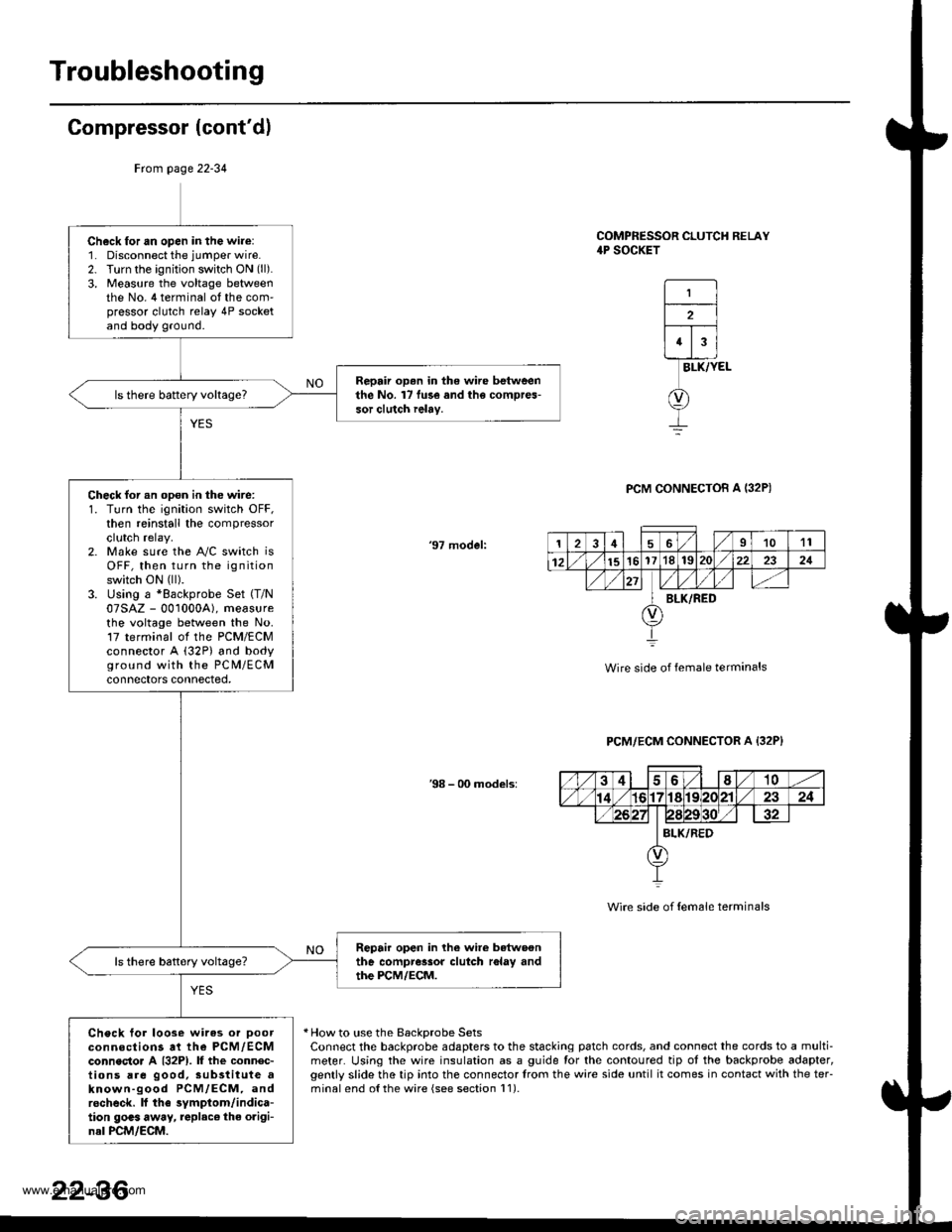
COMPRESSOR CLUTCH RELAY4P SOCKET
1
2
43
BLK/YEL
PCM CONNECTOB A I32P)
'97 model:
Wire side of female terminals
PCM/ECM CONNECTOR A {32P}
38 - 00 models:
Wire side of {em6le terminals
* How to use the BackDrobe SetsConnect the backprobe adapters to the stacking patch cords, and connect the cords to a multi-meter. Using the wire insulation as a guide for the contoured tip ot the backprobe adapter,gently slide the tip into the connector trom the wire side until it comes in contact with the teFminalend o{the wire {see section l1).
Frcm page 22-34
Ch6ck for an open in the wire:1. Disconnect the jumper wire.2. Turn the ignition switch ON (ll).
3, Measure the voltage betweenthe No. 4 terminal ot the com'pressor clutch relay 4P socketand body ground.
Repair op.n in the wire betweenthe No. l7 fu3e and the compres-sor clutch ielay.
Check for an opon in the wire:1. Turn the ignition switch OFF,then reinstall the compressorclutch relay.2. Make sure the A"/C switch isOFF, then turn the ignitionswitch ON (ll).
3. Using a *Backprobe Set (T/N
07SAZ - 001000A), measurethe voltage between the No.17 terminal ol the PCM/ECMconnector A (32P) and bodyground with the PC M/ECMconnectors connected,
Repair open in lhe wire betwoonthe compressor clutch r6lay andthe PCM/ECM.
Check tor loose wires or Doorconnections at the PCM,/ECMconnecto. A {32P1. lf the connec-tions are good, sub3titute aknown-good PCM/ECM, androcheck. lf the symptom/indica-tion goas away, replac€ the origi-nal PCM/ECM.
126I1011
12151617'181S222321
BLK/RED
22-36
www.emanualpro.com
Page 1135 of 1395
Relays
Test
There should be continuity between the No. 1 and No.3
terminals when power and ground are connected to the
No. 2 and No. 4 terminals, and there should be no conti-
nuity when power is disconnected.
3
o Blower motor relay
. Blower motor high relay
,I It)
In P
I)
There should be continuity between the No. 1 and No. 2
terminals when power and ground are connected to the
No. 3 and No. 4 terminals, and there should be no conti-
nuitv when oower is disconnected.
Rsdiator fan relay
Condenser fan relay
Compressor clutch relay
a
a
.I I
tr€
II
F)'"
,2-4.._.
22-45
www.emanualpro.com
Page 1148 of 1395

A/C System Service
Pressure Test Chart
NOTE: Performance Test is on page 22-56.
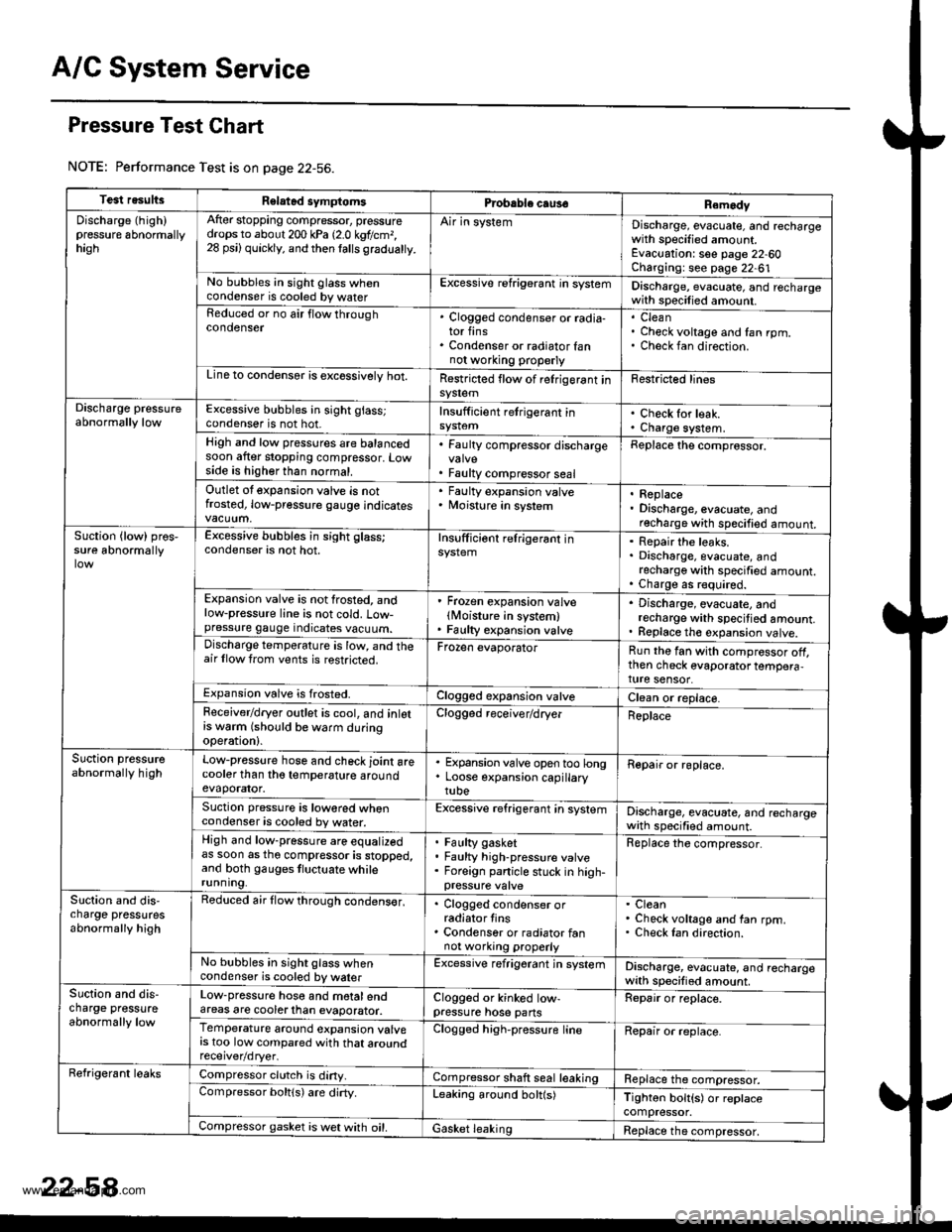
Test resultsRelatad symptomsPrcbable caus€Remody
Discharge (high)pressure 6bnormallyhagh
After stopping compressor, pressuredrops to about 200 kPa 12.0 kgtlcm,,28 psi) quickly, and then lalls gradualty.
Air in systemDischarge, evacuate, and rechargewith specified amount.Evacuation: see page 22-60Charging: see page 22-61No bubbles in sight glass whencondenser is cooled by waterExcessive refrigerant in systemDischarge, evacuate, and rechargewith specilied amount.Reduced or no air flow throughcondenser. Clogged condenser or radia-tor fins. Condenser or radiator fannot wo.king properly
CleanCheck voltage and fan rpm.Check fan direction.
Line to condensor is excossivelv hot.Restricted flow of relrigerant insy$emFestricted lines
Discharge pressureabnormally lowExcessive bubbles in sight glass;condenser is not hot.Insufficient retrigerant inCheck for leak.Charge system.High and low pressures are balancedsoon after stopping compressor. Lowside is higher than normal.
. Faulty compressor discharge
. Faulty compressor seal
Replace the comprossor.
Outlet ot expansion valve is notfrosted, low-pressure gauge indicates
' Faulty expansion valve. Moisture in system. Replace. Discharge, evacuate, andrecharge with specified amount.Suction {low) pros,sure abnormallyExcessive bubbles in sight glass;condenser is not hot.Insufficiont relrigerant inRepair the leaks.Discharge, evacuate, andrecharge with specified amount.Charge as r€quired.Expansion valve is not frosted, andlow-pressure line is not cold. Low-pressure gauge indicates vacuum.
' Frozen expansion valvelMoisture in system). Faulty expansion valve
. Discharge, evacuate, andrecharge with specitied amount.. Replace th€ expansion valve.Discharge temperature is low, and theair llow trom vents is restricted.Frozen evaporatorRun the fan with compressor off,then check evaporator tempera,ture sensor.Expansion valve is frosted.Clogged expansion valveClean or replace.Feceiver/dryer outlet is cool, and inlotrs w6rm (should be warm duringoperation).
Clogged receiver/dryerReplace
Suction pressureabnormally highLow-pressure hose and check joint arecooler than tho temperature aroundevaporator.
. Expansion valve open too long. Loose expansion capillarytube
Repair or roplace.
Suction pressure is lowored whencondenser is cooled by water.Excessive refrigerant in systemDischarge, evacuate, and rechargewath specified amount.High and low-pressure are equalizedas soon as tho compressor is stopped,and both gauges tluctuate whilerunning.
Faulty gasketFaulty high-pressure valveForeign panicle stuck in high-
Replace the compressor.
Slction and dis,charge pressutesabnormally high
Reduced air flow through condens€r,. Clogged condenser orradiator tins. Condenser or radiator fannot working properly
CleanCheck voltage and fan rpm.Check Ian direction.
No bubbles in sight glass whencondenser is cooled by walerExcessive refrigerant jn systemDischarge, evacuate, and rechargewith specified amount.Suction and dis-charge pressureabnormally low
Low-pressure hose and motalendareas are cooterlhan evaporator.Clogged or kinked low-pressure hose pansRepair or replace.
Temperature around expansion valvers too low compared with that aroundClogged high-pressure lineRepair or replace.
Refrigerant leaksCompressor clutch is diny.Compressor shaft seal leakingReplace the compressor.Compressor boltls) are dirty.Leaking around bolt(s)Tighton bolt{s) or replacecompressor.Compressor gasket is wet with oil.Gasket leakingReplace the compressor,
www.emanualpro.com
Page 1152 of 1395

Compressor
Replacement
lf the compressor is marginally operable. run the
engine at idie speed, and let the air conditioner
work for a few minutes. then shut the engine off.
Disconnect the negative cable from the battery.
Recover the refrigerant with a recovery/recycling/
charging station (see page 22-59).
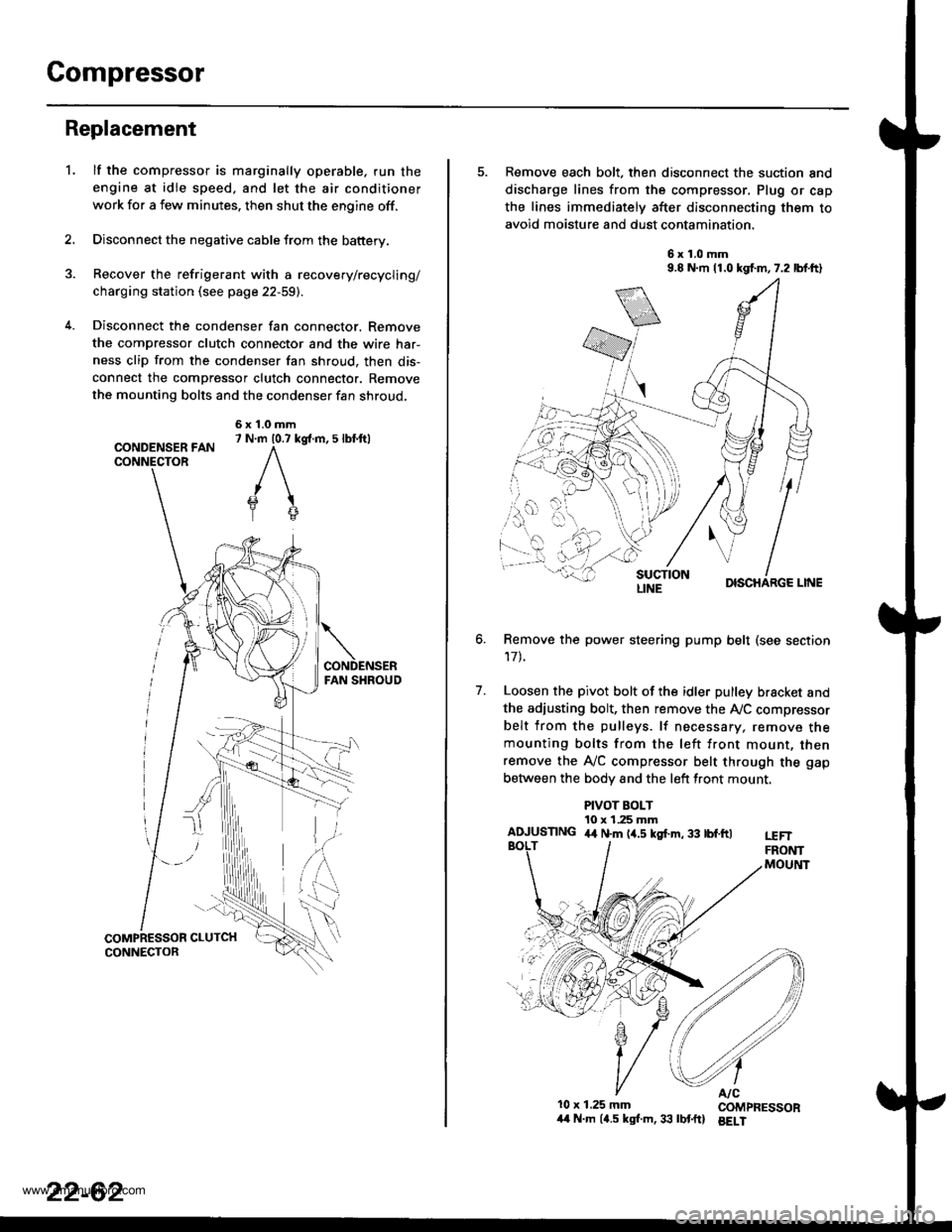
Disconnect the condenser fan connector. Remove
the compressor clutch connector and the wire har-
ness clip from the condenser fan shroud, then dis-
connect the compressor clutch connector. Remove
the mounting bolts and the condenser fan shroud,
CONDENSER FANCONNECTOR
6x1.0mm7 N.m 10.7 kg{.m, 5 lbl.ftl
'L
2.
5. Remove each bolt, then disconnect the suction and
discharge lines from the compressor. Plug or cap
the lines immediately after disconnecting them to
avoid moisture and dust contamination,
6x1.0mm9.8 N.m 11.0 kgf.m,7.2 lbf.ft)
DISCHARGE LINE
Remove the power steering pump belt (see section
17t.
Loosen the pivot bolt of the idler pulley bracket and
the adiusting bolt, then remove the Ay'C compressor
belt from the pulleys. lf necessary, remove themounting bolts from the left front mount, thenremove the A,/C compressor belt through the gap
between the bodv and the left front mount.
6.
7.
PIVOT BOLT10 x 1.25 mmAIUUSTING 4,t N.m (4.5 kgf.m, 33 tbf.ftlt€FTFRONTMOUltlT
10x 1.25 mm COMPRESSOR/t4 N.m (4.5 kgl.m,33 lbtftl BELI
LINE
www.emanualpro.com
Page 1155 of 1395

Clutch Inspection
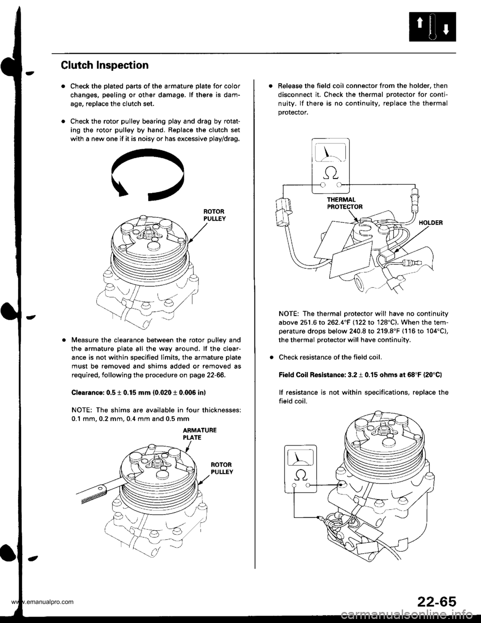
Check the plated parts of the armature plate for color
changes, peeling or other damage. lf there is dam-
age, replace the clutch set.
Check the rotor pulley bearing play and drag by rotat-
ing the rotor pulley by hand. Replace the clutch set
with a new one if it is noisy or has excessive play/drag.
Measure the clearance between the rotor pulley and
the armature plate all the way around. lf the clear-
ance is not within specified limits, the armature plate
must be removed and shims added or removed as
required, following the procedure on page 22-66.
Cloarance: 0.5 t 0.15 mm {0.020 t 0.q)6 in)
NOTE: The shims are available in four thicknesses:
0.1 mm. 0.2 mm. 0.4 mm and 0.5 mm
ABMATUBE
ROTOR
. Release the field coil connector from the holder, then
disconnect it. Check the thermal protector for conti-
nuity, lf there is no continuity, replace the thermal
prorecror.
NOTE: The thermal protector will have no continuity
above 251.6 to 262.4"F 1122 to 128"C). When the tem-perature drops below 240.8 to 219.8"F (116 to 104'C),
the thermal protector will have continuity.
Check resistance of the field coil.
Field Coil Resistance: 3.2 i 0.15 ohms at 68"F {20'C)
lf resistance is not within specifications, replace the
field coil.
22-65
www.emanualpro.com
Page 1156 of 1395
Compressor
Glutch Overhaul
1. Remove the center nut while holding the armature
plate with the tool.
A,/C CLUTCH HOLOERlCommerciallY .vailable)Robinair: P/N 1020,0Ked-Mooro: P/N J37872
CENTER NUT17.6 N.m ('1.8 kgf.m, 13lbfft)Reolace. \
i
2. Remove the armature plate by pulling it up by hand.
ARMATURE PLATE
sHtMls)Replace.
za:s
(i@,
22-66
3. Remove the snap ring B with snap ring pliers. Be
careful not to d8mage the rotor pulley and com-
pressor.
SNAP RING BR6place.
Remove the rotor pulley from the shaft with the
tools. Be sure the claws ot the puller are on the back
of the rotor pulley, not on the belt area; otherwise
the rotor pulley can be damaged.
www.emanualpro.com