1999 HONDA CR-V Service manual
[x] Cancel search: Service manualPage 1149 of 1395
Recovery
Use only service equipment that is U.L.-listed and is cer-
tified to meet the requirements of SAE J2210 to remove
HFC-134a (R-134a) from the air conditioner system.
CAUTION: Exposure to air conditioner refrigerant and
lubricant vapor or mist can irritate eyes, nose and
throat. Avoid brqathing the air conditioner retrigerant
and lubricant vapor or mist.
lf accidental system discharge occurs, ventilate work area
before resuming service.
R-134a service equipment or vehicle air conditioner sys-
tems should not be pressure tested or leak tested with
compressed arr.
@@ some mixtures of air and R-134a have been
shown to be combustible at elevated plessures and can
result in fire or explosion causing iniury or property dam-
age. Never use compressed air to pressure tect R-134a
service equipment or vehicle air conditioner systems.
Additional health and safety intormation may be obtained
from the refrigerant and lubricant manufacturers.
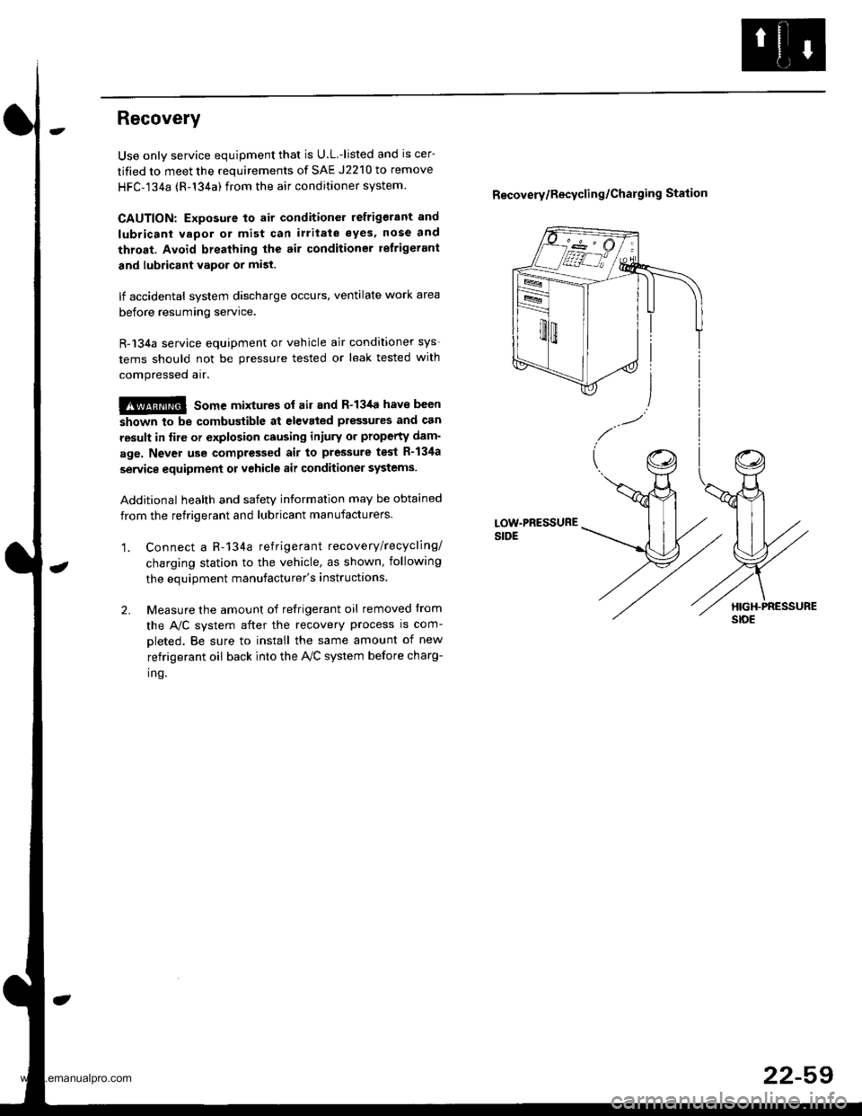
'1. Connect a R-134a refrigerant recove rylrecycling/
charging station to the vehicle, as shown, following
the equipment manufacturer's instructions
2. Measure the amount of refrigerant oil removed trom
the A,/C system after the recovery process is com-
oleted. Be sure to install the same amount of new
refrigerant oil back into the AVC system before charg-
inq.
Recovery/Recycling/Charging Station
22-59
www.emanualpro.com
Page 1150 of 1395
A/C System Service
Evacuation
Use only service equipment that is U.L.-listed and is cer-tified to meet the requirements of SAE J2210 to removeHFC-134a {R-134a)from the air conditioner system.
CAUTION: Exposure to air conditioner refrigerant andlubricant vapor or mist can irrhate eyes, noso and throat.Avoid breathing the air condhioner retrigerant and lubri-cant vapor or mist.
lf accidental system discharge occu.s. ventilate workarea before resuming service.
R 134a service equipment or vehicle air conditioner sys-tems should not be pressure tested or leak tested withcompressed arr.
!@ some mixtures of air and R-134a hsvo beenshown to be combustible at elevated pressures and canresult in tire or explosion causing iniury ot property
damage. Never use compressed air to pressure test R-134a service equipment or vehicle air conditioner svs-tems.
Additional health and safety information may be obtainedfrom the refrigerant and lubricant manufacturers.
1, When an A,/C System has been opened to the atmo-
sphere, such as during installation or repair, it must
be evacuated using a R-l34a refrigerant recovery/
recycling/charging station. {lf the system has beenopen for several days, the receiver/dryer should bereplaced, and the system should be evacuated forseveral hours.)
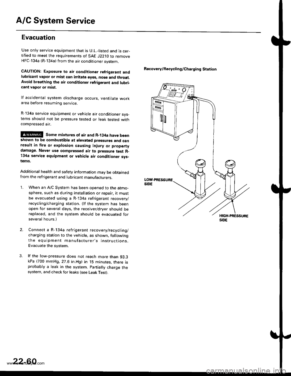
Connect a R-134a refrigerant recovery/recyclin g/
charging station to the vehicle, as shown, following
the equipment manufacturer's instructions.
Evacuate the system,
lf the low-pressure does not reach more than 93.3kPa (700 mmHg,27.6 in.Hg) in 15 minutes, there isprobably a leak in the system. partially charge thesystem, and check for leaks (see Leak Test).
Recovery/Recycling/Charging Station
22-60
www.emanualpro.com
Page 1151 of 1395
Charging
Use only service equipment that is U.L.-listed and is cer-
tified to meet the requirements of SAE J2210 to remove
HFC-134a (R-134a) from the air conditioner system.
CAUTION: Exposure to air conditioner refrigerant and
lubricant vapor or mist can irritate eyes, nose and
throat. Avoid breathing th€ air conditioner refrigerant
and lubricant vapor or mist.
lf accidental system discharge occurs, ventilate work
area before resuming service. Additional health and
safety information may be obtained from the relrigerant
and lubricant manufacturers.
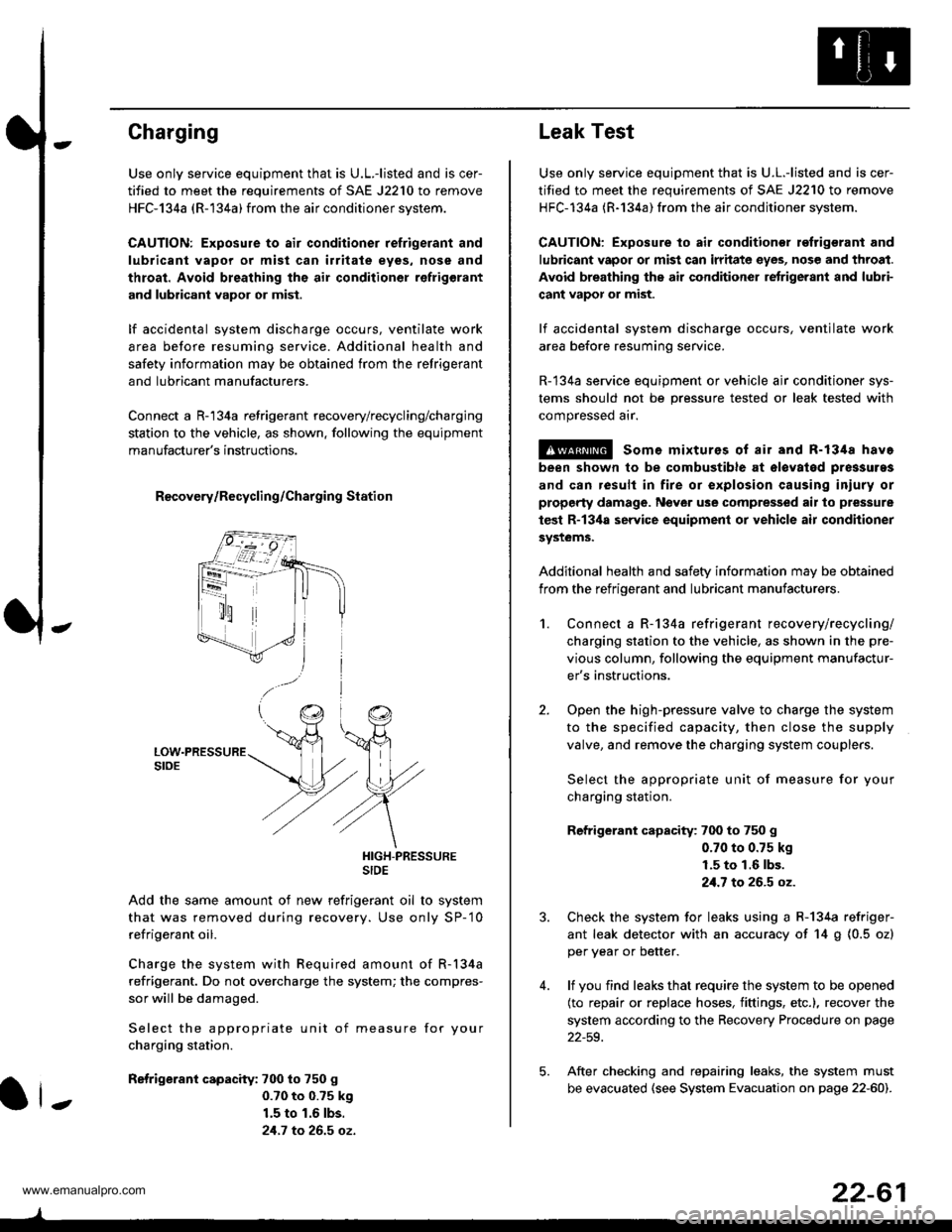
Connect a R-'134a refrigerant recovery/recycling/charging
station to the vehicle, as shown. following the equipment
manufacturer's instructions.
R€covery/Recycling/Charging Station
HIGH-PRESSURESIDE
Add the same amount of new refrigerant oil to system
that was removed during recovery. Use only SP-'10
refrigerant oil.
Charge the system with Required amount of R-134a
refrigerant. Do not overcharge the system; the compres-
sor will be damaged.
Select the appropriate unit of measure for your
charging station.
Refrigerant capacity: 700 to 750 g
0.70 to 0.?5 k9
1.5 to 1.6 lbs.
21.7 to 26.5 oz.
ll-
22-61
Leak Test
Use only service equipment that is U.L.-listed and is cer-
tified to meet the requirements of SAE J2210 to remove
HFC-134a (R-134a) from the air conditioner system.
CAUTION: Exposure to air conditionor refrigerant and
lubricant vapor or mist can irritate eyes, nose and throat.
Avoid breathing the air conditioner retrigerant and lubri-
cant vapor or mist.
lf accidental system discharge occurs, ventilate work
area before resuming service.
R-134a service equipment or vehicle ajr conditioner sys-
tems should not be pressure tested or leak tested with
compressed arr.
!@ some mixturos of air and R-1348 have
been shown to be combustible at olovatod pres3uras
and can result in fire or explosion causing iniury or
property damage. Never use comprelised air to pressure
test R-13ila service equipment or vehicle air conditioner
systems.
Additional health and safety information may be obtained
from the refrigerant and lubricant manufacturers.
2.
1.Connect a R-134a refrigerant recove rylrecycling/
charging station to the vehicle, as shown in the pre-
vious column, following the equipment manufactur-
er's instructions.
Open the high-pressure valve to charge the system
to the specified capacity, then close the supply
valve, and remove the charging system couplers.
Select the appropriate unit of measure for your
charging station.
Refrigerant capacity: 700 to 750 g
0.70 to 0.75 kg
1.5 to 1.6 lbs.
21.7 to 26.5 oz.
Check the system for leaks using a R-134a refriger-
ant leak detector with an accuracy of 14 g (0.5 ozl
per year or better.
lf you find leaks that require the system to be opened
(to repair or replace hoses, fittings, etc.), recover the
system according to the Recovery Procedure on page
22-59.
After checking and repairing leaks, the system must
be evacuated (see System Evacuation on page 22-601.
5.
www.emanualpro.com
Page 1184 of 1395
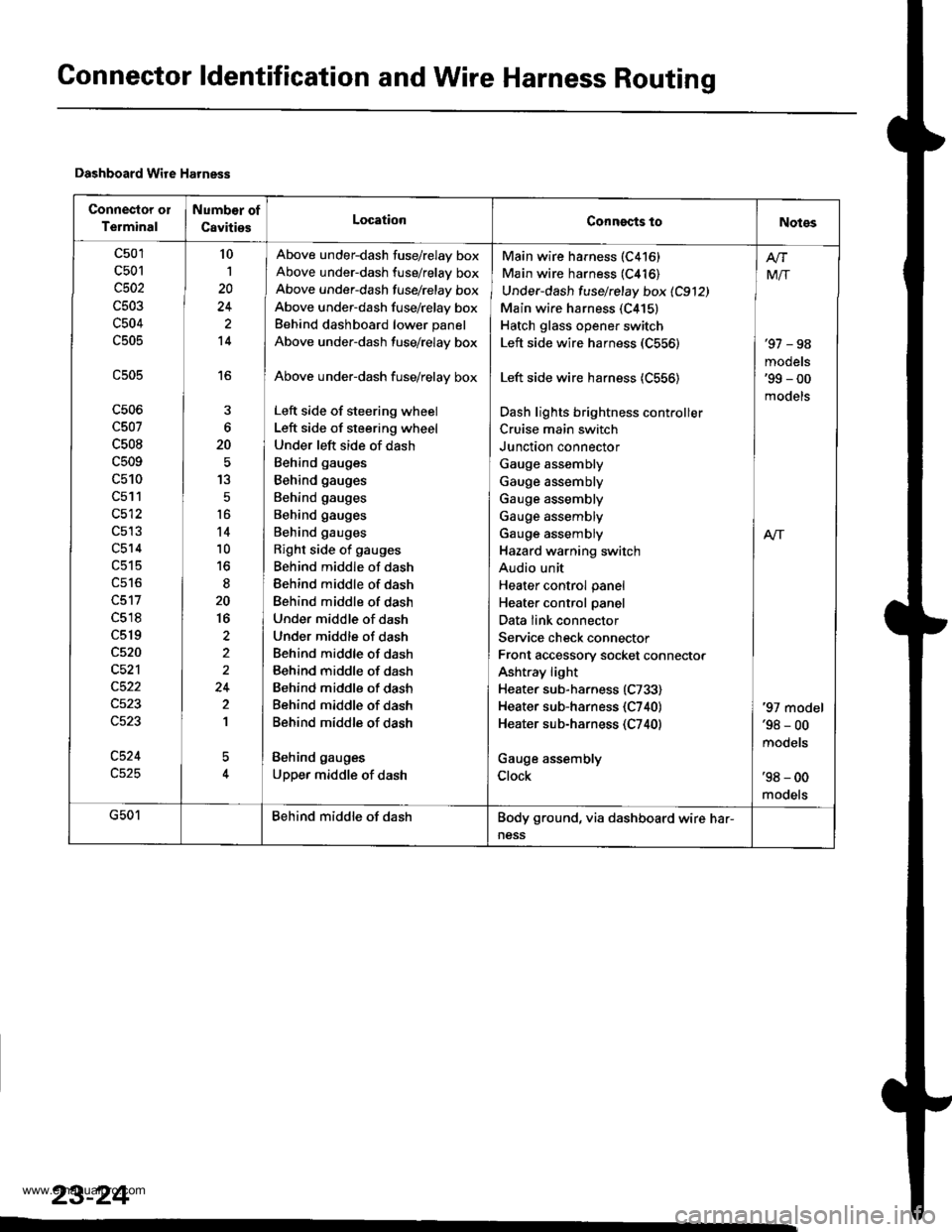
Connector ldentification and Wire Harness Routing
Dashboard Wire Harness
Connector ol
Terminal
Numb€r of
CavitiesLocationConngcts toNotes
c501
c501
c502
c503
c504
c505
c506
c507
c508
c509
c510
c511
c512
c514
c518
c519
c520
c521
c524
10
1
20
14
16
6
20
13
5
t6
14
10
to
20
16
2
24
2
1
5
Above under-dash fuse/relay box
Above under-dash fuse/relay box
Above under-dash fusehelay box
Above under-dash fuse/relay box
Behind dashboard lower panel
Above under-dash fuse/relay box
Above under-dash fuse/relay box
Left side of steering wheel
Left side of steering wheel
Under left side of dash
Behind gauges
Behind gauges
Behind gauges
Behind gauges
Behind gauges
Right side of gauges
Behind middle of dash
Behind middle of dash
Behind middle of dash
Under middle of dash
Under middle of dash
Behind middle of dash
Behind middle of dash
Behind middle of dash
Behind middle of dash
Behind middle of dash
Behind gauges
Upper middle of dash
Main wire harness (C416)
Main wire harness (C416)
Under-dash fuse/relay box 1C912)
Main wire harness (C415)
Hatch glass opener switch
Left side wire harness (C556)
Left side wire harness (C556)
Dash lights brightness cont.oller
Cruise main switch
Junction connector
Gauge assembly
Gauge assembly
Gauge assembly
Gauge assembly
Gauge assembly
Hazard warning switch
Audio unit
Heater control panel
Heater control panel
Data link connector
Service check connector
Front accessory socket connector
Ashtray light
Heater sub-harness (C733)
Heater sub-harness {C740}
Heater sub-harness (C740)
Gauge assembly
Clock
'97 - 98
models'99 - 00
models
Mir
A/r
'97 model'98 - 00
mooets
'98 - 00
models
G501Behind middle of dashBody ground, via dashboard wire har-
ness
23-24
www.emanualpro.com
Page 1207 of 1395

BLKG401
GroundWir€ ColorComponent or Circuits Grounded
ABS indicator circuit
ABS control unit
Ashtray light
A/T gear position indicator dimming circuit
Brake fluid level switch
Clock ('98 - 00 models)
Clutch inrerlock switch (M/T)
Clutch switch (Mff)
Cruise main switch
Cruise indicator circuit
Cruise control unit
Dash lights brightness controller
Data iink connector
Daytime running rights control unit (Canada)
Front accessary socket
Gauge and indicators
Heater control panel
lgnition key light control unit ('97 model)
lgnition key switch
Integrated control unit
Interlock control unit (Ay'T)
Parking pin switch {A,/T)
Power window relay
Rear accessary socket relay
Bear window defogger relay
Rear window wiper control unit ('97 model)
Service check connector
Spotlights
SRS indicator circuit
Turn signal/hazard relay
Windshield wiper motor
Windshield wiper/washer switch- plus everything grounded through G402
ABS control unit
Blower motor relay
Blower motor high relay
ELD unit (USA)
Power transistor- plus everything grounded through G401
BLKG402
{cont'd)
23-47
www.emanualpro.com
Page 1215 of 1395
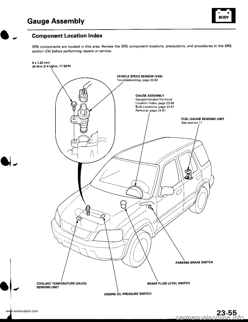
Gauge Assembly
Component Location Index
SRS components are located in this area. Review the SRS component locations, precautions, and procedures in the SRS
section {24} before performing repairs or service.
I x 1.25 mm24 N.m {2.4
VEHICLE SPEED SENSOF {VSS'Troubleshooting, page 23-62
GAUGE ASSEMBLYGau ge/lndicator/TerminalLocation Index, page 23-56Bulb Locations, page 23-57Removal, page 23-61
J-
FUEL GAUGE SENDING UNITSee section 1 l
PARKING BRAKE SWITCH
COOLANT TEMPERATURE GAUGESENDING UNITBRAKE FLUID LEVEL SWITCH
ENGINE OIL PRESSURE SWITCH
www.emanualpro.com
Page 1228 of 1395
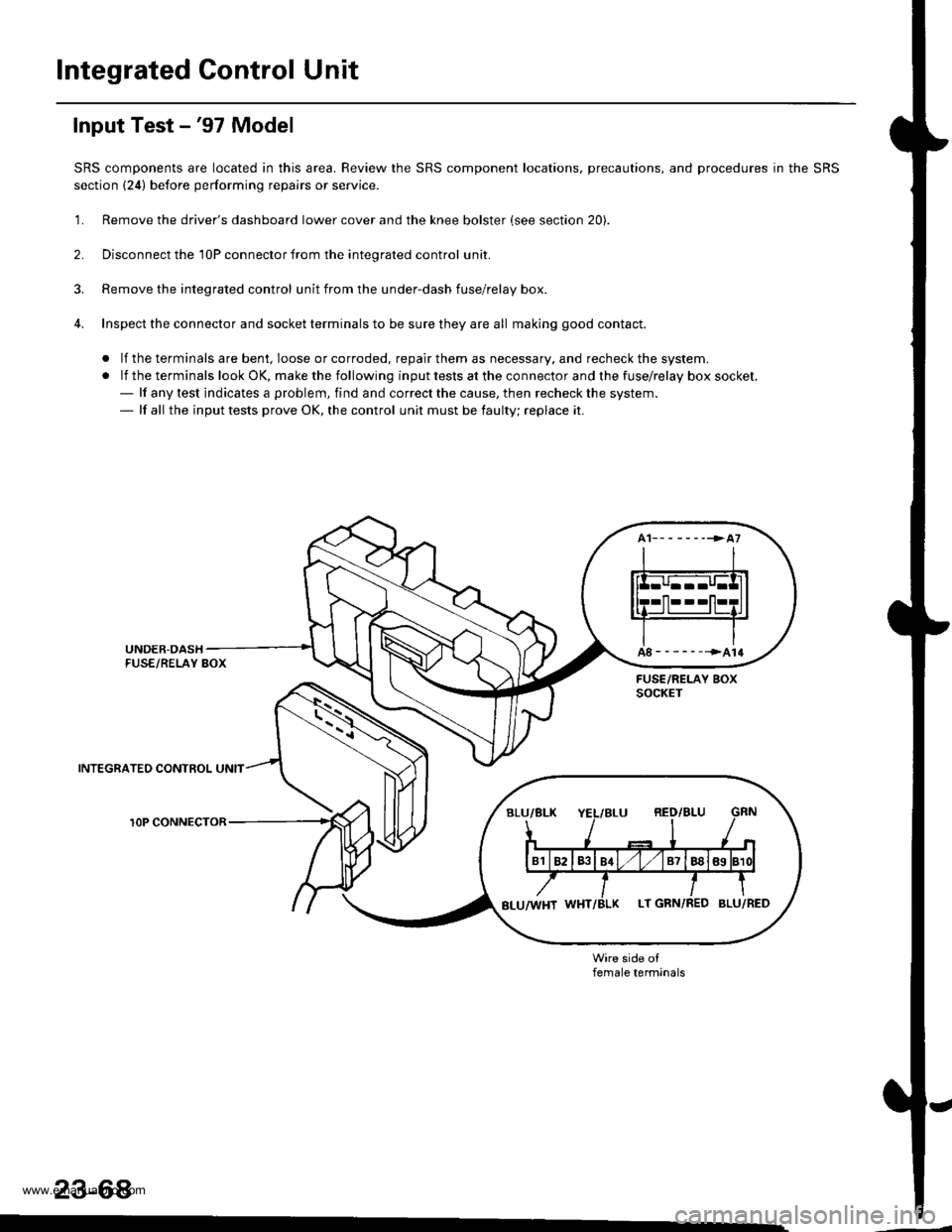
Integrated Gontrol Unit
Input Test -'97 Model
SRS components are located in this area. Review the SRS component locations, precautions, and procedures in the SRS
section {24) before performing repairs or service.
'1. Remove the driver's dashboard lower cover and the knee bolster (see section 20).
2. Disconnect the 'l0P connector from the inteorated control unit.
3. Remove the integrated control unit from the under-dash fuse/relay box.
4. Inspect the connector and socket terminals to be sure they are all making good contact.
. lf the terminals are bent, loose or corroded, repair them as necessary, and recheck the system.
.lftheterminalslookOK,makethefollowinginputtestsattheconnectorandthefuse\
/relayboxsocket.- lf any test indicates a problem, find and correct the cause, then recheck the system.- lf all the input tests prove OK, the control unit must be faulty; replace it.
INTEGRATEO CONTROL UNIT
rOP CONNECTOR
female terminals
23-68
www.emanualpro.com
Page 1231 of 1395
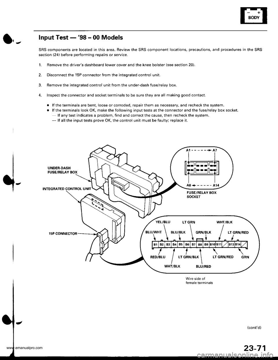
Input Test -'98 - 00 Models
SRS components are located in this area. Review the SRS component locations, precautions, and procedures in the SRS
section (24) before performing repairs or service.
L Remove the driver's dashboard lower cover and the knee bolster (see section 20).
2. Disconnect the 'l5P connector from the inteqrated control unit.
3. Remove the integrated control unit from the under-dash fuse/relay box.
4. Inspect the connector and socket terminals to be sure they are all making good contact.
. lf the terminals are bent, loose or corroded. repair them as necessary, and recheck the system.
.lftheterminalslookOK,makethefollowinginputtestsattheconnectorandthefuse\
/relayboxsocket.
lf any test indicates a problem, find and correct the cause, then recheck the system.- lf all the input tests prove OK, the control unit must be faulty; replace it.
UNDER-DASHFUSE/RELAY BOX
INTEGRATED CONTROL UNIT
15P CONNECTOR
A8<------A14
YEL/BLU LT GRN WHT/BLK
www.emanualpro.com