Page 359 of 1395

'98 - 00 models:ECM/PCM CONNECTORS
ECM/PCM CONNECTOR A (32PI
Wire side of female terminals
ECM/PCM CONNECTORS
A (32P1
ACC (BLK/REOI
LG1 (BRN/BLKI
{cont'd)
11-157
A {32P1
Check for a shott in the wire
{ACS linel:1. Turn the ignition switch OFF.
2. Disconnect the A/C Pressureswitch 2P connector.3. Turn the ignition switch ON (ll)
4. Measure vo ltage betweenECM/PCM connector terml
nals A27 and 820.
Check tor . short in the wire IACSlinel:1. Turn the ignition switch OFF.
2. Disconnect ECM/PCM connec-tor A (32P).
3. Check for continuity betweenbody ground and ECM/PCMconnector terminal A27.
ls there battery voltage?
R.oak short in the wile between
rhe ECM/PCM (A271 and the A/C
Dressure switch.ls there continuitv?
Sub6titute a known{ood ECM/
rcM and recheck. lf pte6cribed
voltage i3 now available, re'pl.ce the origioal ECM/rcM.See ih6 air conditioner inspec-
tion (s6e section 221.
Check for an open in the wire(ACC line):'1. Turn the ignition switch OFF.
2. Reconnect the A/C Pressureswitch 2P conneclor.3. Turn the ignition switch ON (ll).
4. Momentarily connect ECM/PCM connector terminals A17
and 820 with a jumPer wireseveralllmes,
{To page 11 158)JUMPER WIRE
www.emanualpro.com
Page 360 of 1395

ldle Control System
Air Gonditioning Signal (cont'd)
JUMPERWIRE
UNDER-HOOD FUSE/RELAYBOX 9P CONNECTOR {G'52I
23a
5589
ACC (BLK/R
Wire side otACC (BLK/RED'
Wire side otfemaleterminals
ECM/PCM CONNECTORS
Wire sid€ of female torminals
(From page '11,157)
Check Ior dn opon in the wiroIACC linel:Momentarily connect the under-hood fuse/relay box 9P connectorterminal No. 5 to body groundwith a jumper wire several times.
ls there a clicking noise lromthe y'y'C compressor clutch?
ls there a clicking noise fromtho A,/C comprossor clutch?Sae rir conditional in3pactionlroa saction 221.
Repai. open in th6 wiro lr€twlanthe ECM/PCM lAl7l .nd tho A/Cclutch rolay.
Check tho op.ration of tho A/C:1. Stan the engine.2. Turn the blower switch ON.3. Turn the Ay'C switch ON.
ChGGk for an open in the wi.eIACS linel:Measure voltage betweon ECM/PCM connector terminals A27and 820.
Does the !y'C operate?
Air conditioning 3ignal i3 OK.
Rap.ir opon in the wir6 bdtunaanrh. Ecil/FcM lA27l rnd rh. A/crwitch.
ls voltage less than 1.0 V?
Sub6lftna a known{ood ECM/PCM and rechock. lf symp-tom/indicetion goes away.roplace the original ECM/rcM.See the ah conditionor inspoc-tion {3e€ section 22},
www.emanualpro.com
Page 364 of 1395

ldle Gontrol System
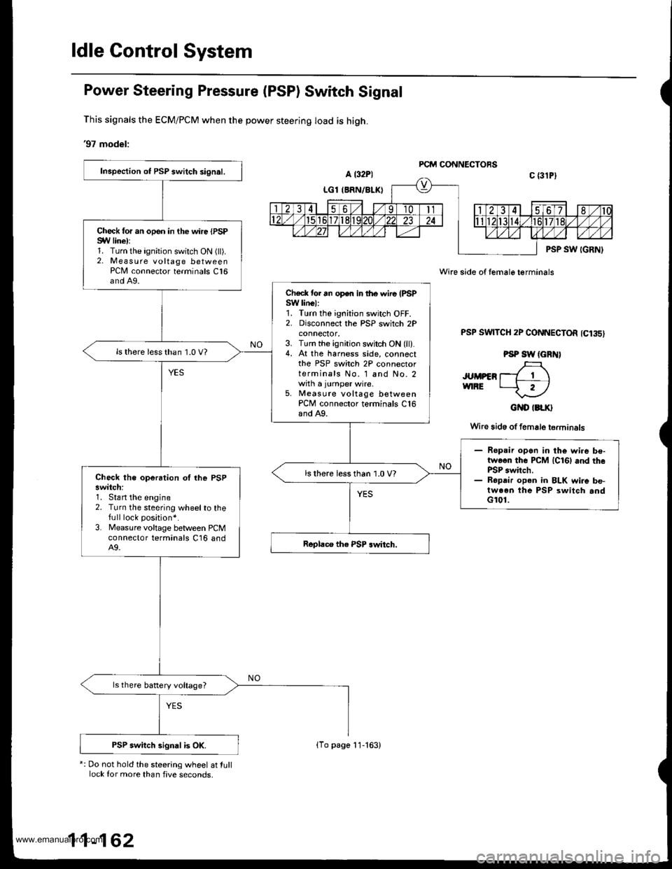
Power Steering Pressure (PSP) Switch Signal
This signals the ECM/PCM when the power steering load is high.
'97 model:
*: Do not hold the steering wheel at tulllock for more than five seconds,
Wire side of female terminals
PSP SWTTCH 2P CONNECTOR 1C135)
PSP SW (GRN)
JUMPER T_7 1 \vnRE t--f r)
GND IBLK}
Wire 3id6 of female terminals
Inspection ot PSP switch signal.
Check for an open in the wire {PSPSYV line):1. Turn the ignition switch ON (ll).2. Measure voltage betweenPCN4 connector terminals C16and A9.
Check tor an open in lhe wire (PSPSW linel:1. Turn the ignition switch OFF.2. Disconnect the PSP switch 2Pconnecror,3. Turn the ignition switch ON (ll).4. At the harness side, connectthe PSP switch 2P connectorterminals No. 1 and No. 2with a jumper wire.5, Measute voltage betweenPCM connector terminals C16and A9.
ls there less than 1.0 V?
- Ropsir open in the wi.e be-twoon the PCM lcl6l and thePSP switch.- Ropdir open in BLK wire be-tween the PSP switch andG101.
ls there less than 1.0 V?Check the operation oI lhe PSPswitch:1. Stan the engine2. Turn the steering wheelto thefull lock position*.
3. Measure voltage between PCMconnector terminals C16 andA9.
ls there battery voltage?
PSP switch signal is OK.(To page 11-163)
www.emanualpro.com
Page 365 of 1395
{From page 11 162)
PCM CONNECTORS
Wire side of female terminals
c t3lPl
Check for a short in the PSP
swilch:1. Turn the ignition switch OFF.2. Disconnect the 2P connectorfrom the PSP switch.3. Turn the ignition switch ON (ll).
4. lleas u re voltage betweenPCM connector terminals C16and A9.
Check tor a short in the wire (PSP
SW linol:1. Turn the ignition switch OFF.2. Disconnect PCM connector C(31P).
3. Check for continuity betweenbody ground and PCM connec-tor terminal C16.
Reoair short in the wire betwoonrhe PCM {C16) and the PSP3witch.
Substitute a known-good PCM
and rocheck. lf proscribod volt-age b now available, replace theoriginal PCM.
(cont'd)
-16311
www.emanualpro.com
Page 366 of 1395

ldle Control System
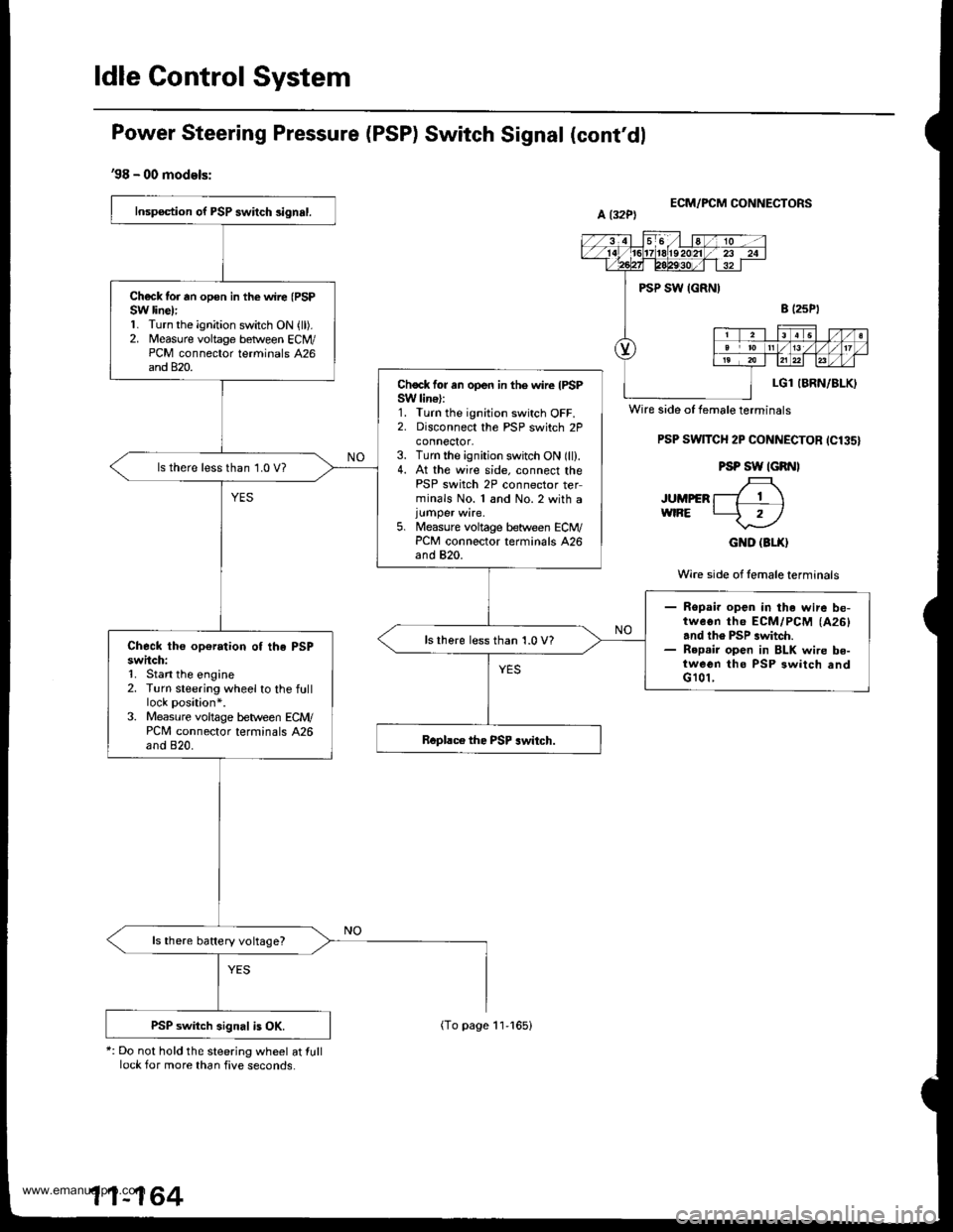
Power Steering Pressure (PSP) Switch Signal (cont'dl
'98 - 00 models:
*: Do not hold the steering wheel at lulllock for more than five seconds.
ECM/FCM CONNECTORS
PSP SwlTCH 2P CONNECTOR ICl35}
PSP SW IGRNI
JUMpER f-7 T \wtRE L-5 rl
GND (3LX}
Wire side of lemale terminals
Inspection of PSP swilch 3ignal.
Ch€ck tor rn opon in the wire (PSP
SW line):1. Turn the ignition switch ON {ll).2. Measure voltage betlveen ECM/PCM connector terminals 426and 820.
Chock for an open in the wire IPSPSW lin€):1. Turn the ignition switch OFF.2. Disconnect the PSP switch 2Pconnector,3. Turn the ignition switch ON (ll).4. At the wire side. connect thePSP switch 2P connector terminals No. 1 and No.2 with a
5. Measure voltage between ECM/PCM connector terminals 426and 820.
ls there less than 1.0 V?
- Ropai. open in the wire be-tweon th6 ECM/PCM (A26)
and th6 PSP .witch.- R6p.ir open in BLK wire be-tween tho PSP 3witch andG 101,
lsthere less than 1.0 V?Check the op€ration of the PSPswitch:1. Stan the engine2. Turn steering wheel to the fulllock position*.3. Measure voltage b€tween ECM/PCM connector terminals A26and 820.
ls there battery voltage?
PSP switch signal is OK.
Wire side of female terminals
11-164
(To page 11-165)
www.emanualpro.com
Page 367 of 1395
{From page 11 164i
Check for a short in the PSPswitch:1. Turn the ignition switch OFF.2, Disconnect the 2P connectorfrom the PSP switch.3. Turn the ignition switch ON (ll).
4. Measure voltage betlveen ECM/PCM connector terminals A26and 820.
Check lor e 3hort in the wire IPSPSW linell1. Turn the ignition switch OFF.2. Disconnect ECM/PCM con-nector A (32P).
3. Check for continuity betweenbody ground and ECM/PCMconnector terminal A26.
ReDair short in the wir€ bstweenthe ECM/PCM (A26) and the PSPswitch.
Substitute a known-good ECM/PCM and rechock. It Drescribodvoltago is now available, roplacethe origin.l ECM/PCM,
ECM/PCM CONNECTORS
A l32Pl
Wire side of female terminals
Wire side of female terminals
1 1-165
www.emanualpro.com
Page 368 of 1395
ldle Control System
Brake Switch Signal
This signals the ECM/PCM when the brake pedal is depressed.
('97 model)'- - - - -_- Il
PCM CONNECTORSa t32P) D ll6Pl
BKSW(GRN/WHT)
Wire side of female terminals
Insp€ction of Brak. Switch Signal.
Are the brake lights on withoutpressing the brake pedal?
Inspect the HORN, STOP {15 A)fuse in the undeFhood luse/ relaybox.Do the brake lights come on?
Reoair short in the wire be-tween th€ b.ake switch andth6 HoRN, STOP {15 A)luso,Replaco the HoRN, STOP (15
Al fuse.
Repair op6n in the wir€ be-tween the brake switch andtho HORN, STOP (15 Allus6.Inspect the brrke switch (see
aection l9l.
Check tol .n open in the wire{BXSW linel:1. Press the brake pedal.2. Measure voltage between rcMconnector terminais D5 and Agwith the brake pedal pressed.
Reprir open in the wire betweenthe PcM lD5l rnd the brakeswitch.
(To page 11-167)
1 1-166
www.emanualpro.com
Page 369 of 1395
(From page 11-166)
Chock for en open in the wire(BKSW line):1. Press the brake pedal.
2. Measure vohage between ECM/PCM connector terminals A32and 820 with the brake pedalpressed.
Ropair opon in tha wire bstwsonrhe ECM/PCM lA32l rnd thebrako switch.
Brake switch signd b OK.
ECM/FCM OONNECTORS
Wire side of femalo terminals
11-167
www.emanualpro.com