1999 HONDA CR-V Adjust Ac
[x] Cancel search: Adjust AcPage 927 of 1395
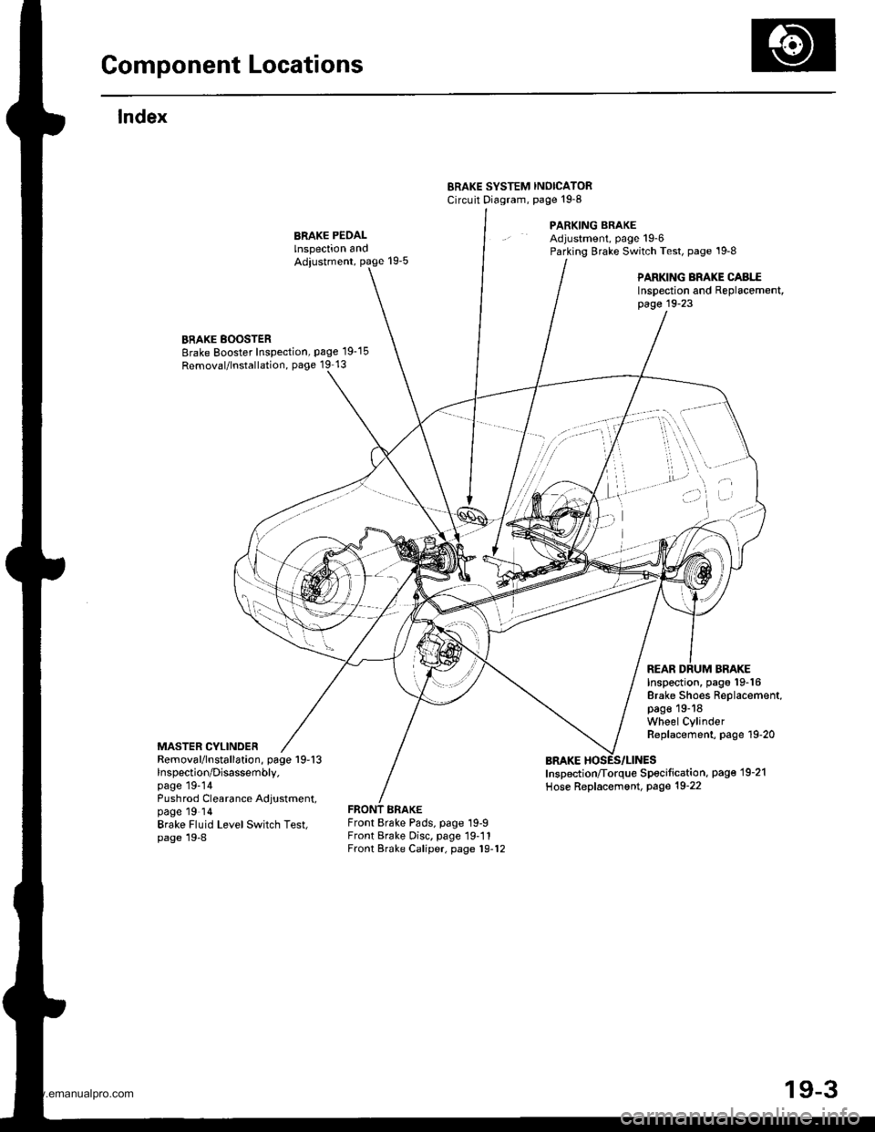
Gomponent Locations
lndex
ERAKE SYSTEM INOICATORCircuit Diagram, page't9-8
PARKING BRAKEAdjustment, page 19-6Parking Brake Switch Test, page '19-8
PARKING BRAKE CABI..EInspection and Replacement,page 19-23
BRAKE BOOSTERBrake Booster Inspection, page 19-15
Removal/lnstallation, page 19 13
MASTER CYLINDER
Inspection, pago 19-16Brake Shoes Replacement,page 19-18Wheel CylinderReplacement, page 19-20
REAR DRUM BRAKE
Removal/lnstallation, page 19-13lnspection/Disassembly.page 19-14Pushrod Clearance Adjustment,page 19 ldBrake Fluid LevelSwitch Test,page 19-8
Inspection/Torque Specification, pag€'19-21
Hose Replacement, Page 19-22
Front Brake Pads, page 19-9Front Brake Disc. page 19-11Front Brake Caliper, page 19-12
)i't ' -"''
/'"''t,'..,1 ...,. , \,,,.
i ,.'
'a.,
I
.) ..)
t ^fl)
19-3
www.emanualpro.com
Page 928 of 1395
Inspection and Adjustment
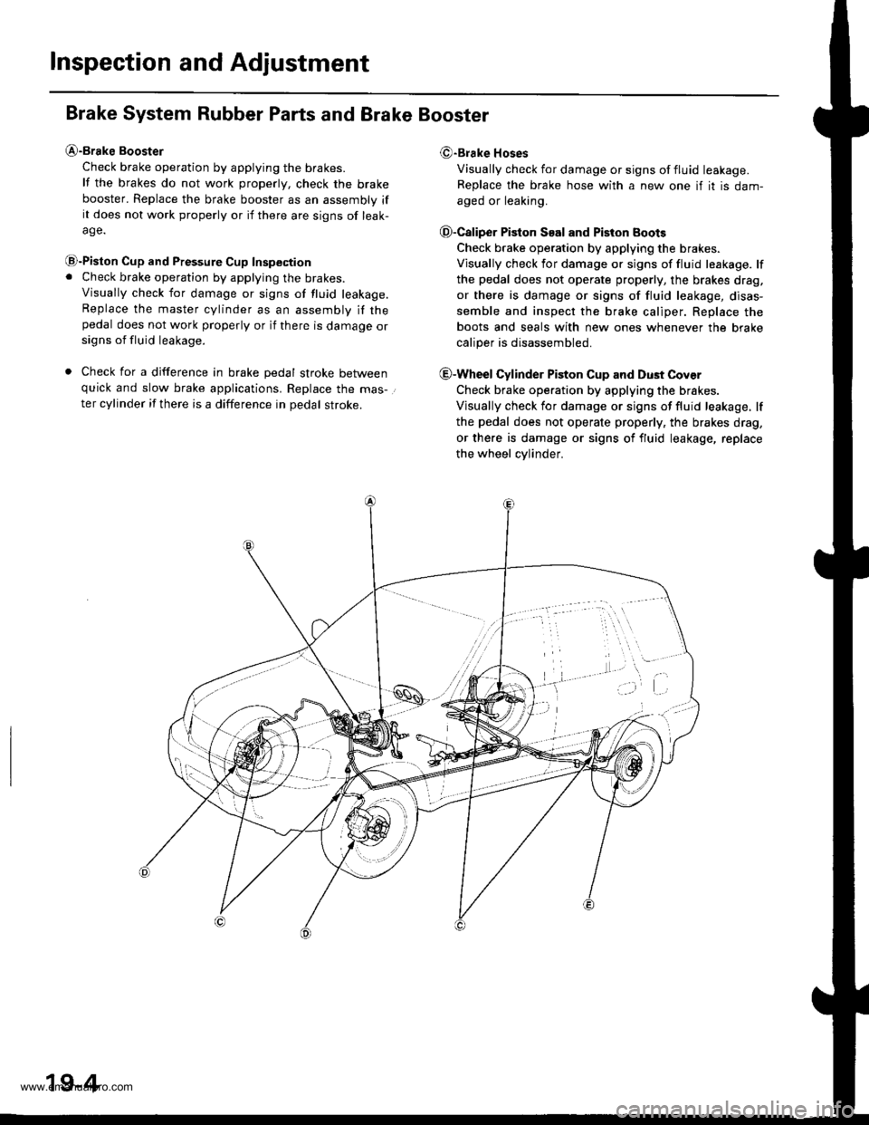
Brake System Rubber Parts and Brake Booster
@-Brake Booster
Check brake operation by applying the brakes.
lf the brakes do not work properly, check the brake
booster. Replace the brake booster as an assembly ifit does not work properly or if there are signs of leak-
age.
@-Piston Cup and Pressure Cup Inspection. Check brake operation by applying the brakes.
Visually check for damage or signs of tluid leakage.Replace the master cylinder as an assembly if thepedal does not work properly or if there is damage orsigns of fluid leakage.
. Check for a difference in brake pedal stroke betweenquick and slow brake applications. Replace the mas-.
ter cylinder if there is a difference in pedal stroke.
(9-Brake Hoses
Visually check for damage or signs of fluid leakage.
Replace the brake hose with a new one if it is dam-
aged or leaking.
O-Caliper Piston S€al and Piston Boots
Check brake operation by applying the brakes.
Visually check for damage or signs of fluid leakage. lf
the pedal does not operate properly, the brakes drag,
or there is damage or signs of fluid leakage, disas-
semble and inspect the brake caliper. Replace the
boots and seals with new ones whenever the brake
caliper is disassembled.
@-Wheel Cylinder Piston Cup and Dust Cover
Check brake operation by applying the brakes.
Visually check for damage or signs of fluid leakage. lf
the pedal does not operate properly, the brakes drag,
or there is damage or signs of fluid leakage, replace
the wheel cvlinder.
19-4
www.emanualpro.com
Page 929 of 1395
Brake Pedal
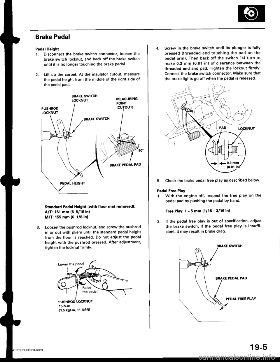
Pedal Hoight
1. Disconnect the brake switch connector, loosen the
brake switch locknut, and back off the brake switch
until it is no longer touching the brake pedal.
2. Lift up the carpet, At the insulator cutout, measure
the pedal height from the middle of the right side of
the oedal pad.
BRAKE SWITCH
ERAKE SWITCH
Standard Pedal Height (with floor m8i removed):
A/T: 161 mm (5 5/16 in)
M/T: 155 mm {6 U8 in}
Loosen the pushrod locknut, and screw the pushrod
in or out with pliers until the standard pedal height
from the floor is reached. Do not adjust the pedal
height with the pushrod pressed. After adiustment,
tighten the locknut firmly.
PUSHROD LOCKNUT
15 N.m11.5 kgj m, 11 lbf ftl
4. Screw in the brake switch until its plunger is fully
pressed (threaded end touching the pad on the
pedal arm), Then back otf the switch 1/4 turn to
make 0.3 mm (0.01 in) of clearance between the
threaded end and pad. Tighten the locknut firmly.
Connect the brake switch connecto.. Make sure that
the brake lights 90 off when the pedal is released
5. Checkthe brake pedalfree play as described below
Pedal Free Play
1. With the engine off. inspect the free play on the
pedal pad by pushing the pedal by hand-
Free Play: 1 - 5 mm (1/16 - 3/16 in)
2. lf the pedal free play is out of specification, adiust
the brake switch. lf the pedal free play is insuffi-
cient, it may result in brake drag.
swtTcH
PEOAL PAD
PEDAL FREE PLAY
19-5
www.emanualpro.com
Page 930 of 1395
Inspection and Adjustment
Parking Brake
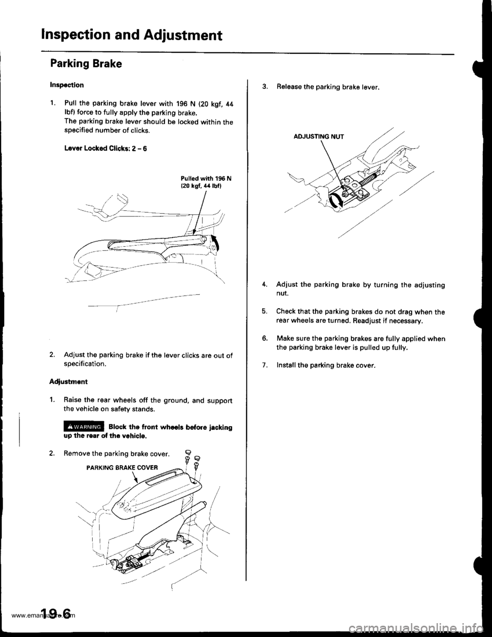
Inspeqtion
1. Pull the parking brake lever with
lbfl force to fully apply the parking
The parking brake lever should be
specified number of clicks.
L.var Lockod Clicks: 2 - 6
196 N (20 kqf, 44
brake.
locked within the
2. Adjust the parking brake if the lever clicks are out ofspecification.
Adiustment
1. Raise the rear wheels off the ground. and support
the vehicle on safety stands.
@@ Bbck tho front who€ts betore iackingup the rear ot tho vohicle.
2. Remove the parking brake cover
PARKING BRAKE COVER
19-6
3. Release the parking brake lever.
Adjust the parking brake by turning the adjusting
nut.
Check that the parking brakes do not drag when therear wheels are turned. Readjust if necessary.
Make sure the parking brakes are fully applied when
the parking brake lever is pulled up fully.
Installthe parking brake cover.7.
www.emanualpro.com
Page 932 of 1395
![HONDA CR-V 1999 RD1-RD3 / 1.G Workshop Manual
Inspection and Adjustment
Brake System Indicator
Circuit Diagram lNuLR.HorJDGNrT 0llSt!ITCHUNDEB.DASHFUSE]NEtAY BOIrllA Nl] 42 4!A
PAF�K NC BRA(E S\IICH
GBNiBEO
Io\lt j I ERAKE tuU 0 rEVEr 9!1 I(N
| HONDA CR-V 1999 RD1-RD3 / 1.G Workshop Manual
Inspection and Adjustment
Brake System Indicator
Circuit Diagram lNuLR.HorJDGNrT 0llSt!ITCHUNDEB.DASHFUSE]NEtAY BOIrllA Nl] 42 4!A
PAF�K NC BRA(E S\IICH
GBNiBEO
Io\lt j I ERAKE tuU 0 rEVEr 9!1 I(N
|](/manual-img/13/5778/w960_5778-931.png)
Inspection and Adjustment
Brake System Indicator
Circuit Diagram lNuLR.HorJDGNrT 0llSt!ITCHUNDEB.DASHFUSE]NEtAY BOIrllA Nl] 42 4!A
PAF�K NC BRA(E S\I'ICH
GBNiBEO
Io\lt j I ERAKE tuU 0 rEVEr 9!1 I(N
| oPt^r'f,'1 .r
BIKI-o-:G401
Parking Brake Switch Test
1. Remove the parking brake cover,
2. Disconnect the connector from the parking brakeswitch.
3. Check for continuity between the terminal and bodyground in each position according to the table.
Terminal
Lever Position \
Positive
TerminalBody Ground
Lever Up--o
Lever Down
NOTE (Canada): lf the parking brake switch is OK, butthe brake system indicator does not function, perform
the input test for the daytime running lights control unit(see section 23).
Brake Fluid Level Switch Test
1. Remove the reservoir cap. Check that the float
moves up and down freely; if it doesn't, replace the
reservoir cap assembly.
2. Check for continuity between the terminals in each
switch position according to the table.
- r9''r
Position12
FLOAT UP
FLOAT DOWNo
RESERVOIR CAP
GROUND
Switch contacts open atproper fluid level.
19-8
www.emanualpro.com
Page 937 of 1395

Master Cylinder/Brake Booster
Removal/lnstallation
1, Disconnect the brake fluid level switch connectors.
2. Remove the reservoir cap from the master cylinder.
3. Remove the brake fluid from the master cvlinder
reservoir with a syringe.
4. Disconnect the brake lines from the master cylinder.
To prevent spills, cover the line joints with rags or
shop towels.
5. Remove the master cylinder mounting nuts and
wasners.
6. Remove the master cylinder from the brake booster.
CAUTION: Be careful not to bend or damage the
brake lines when removing the master cylinder.
Do not spill brake fluid on the vehicle; it may dam.
age the paint; it brake fluid does cont.ct the paint,
wash it oft immediately with water.
7. Disconnect the vacuum hose from the brake booster.
8. Remove the cotter pin and clevis pin from the clevis.
Do not disconnect the clevis by removing it from
the operating rod of the brake booster. lf the clevis
is loosened, adjust the pushrod length before
installing the brake booster (see page 19-15).
To Front Caliper (Without ABS)
\\
15 N.m {1.5 kgtm, vAcuuM HosE
r r rbf.ft) |
/ | BRAKE FLUTD LEvEL
/l /
swrrcHcoNNEcroRs
/ I I I COTTER PIN
I I / neotace
l,/-- ro Rear wheet cylinders / | I
h ./-''' /. I I IYli //*s (.S
I /r:
9. Remove the four booster mounting nuts.'10. Pull the brake booster forward until the clevis is
clear of the bulkhead.
11. Remove the brake booster from the enqine com-
panment.
12. Install the brake booster and master cylinder in the
reverse order of removal, and note these items:
. When connecting the brake lines, make sure that
there is no interference between the brake lines
and other parts.
. Be careful not to bend or damage the brake lines
when installing the master cylinder.
. lf replacing the master cylinder or brake booster,
check and adjust the pushrod clearance before
installing the master cylinder (see page 19-14).
Fill the master cylinder reservoir, and bleed the
brake system (see page 19-7).
After installation, check the brake pedal height and
brake pedal free play (see page 19-5), and adjust if
necessary.
13 N.m 11.3 kg{.m,I rbf.ft)
13.
14.
To Master Cylinder(Without ABS)To Modulator Unit(with ABs)@-\
\
^ To Front Caliper
9i\.
-#qCLEVIS PIN
):-,/
PROPORTIONING CONTROL VALVE
MASTER CYLINDER
15 N.m (1.5 kgf.m, 11 lbl.ftl
BRAXE BOOSTER
www.emanualpro.com
Page 938 of 1395
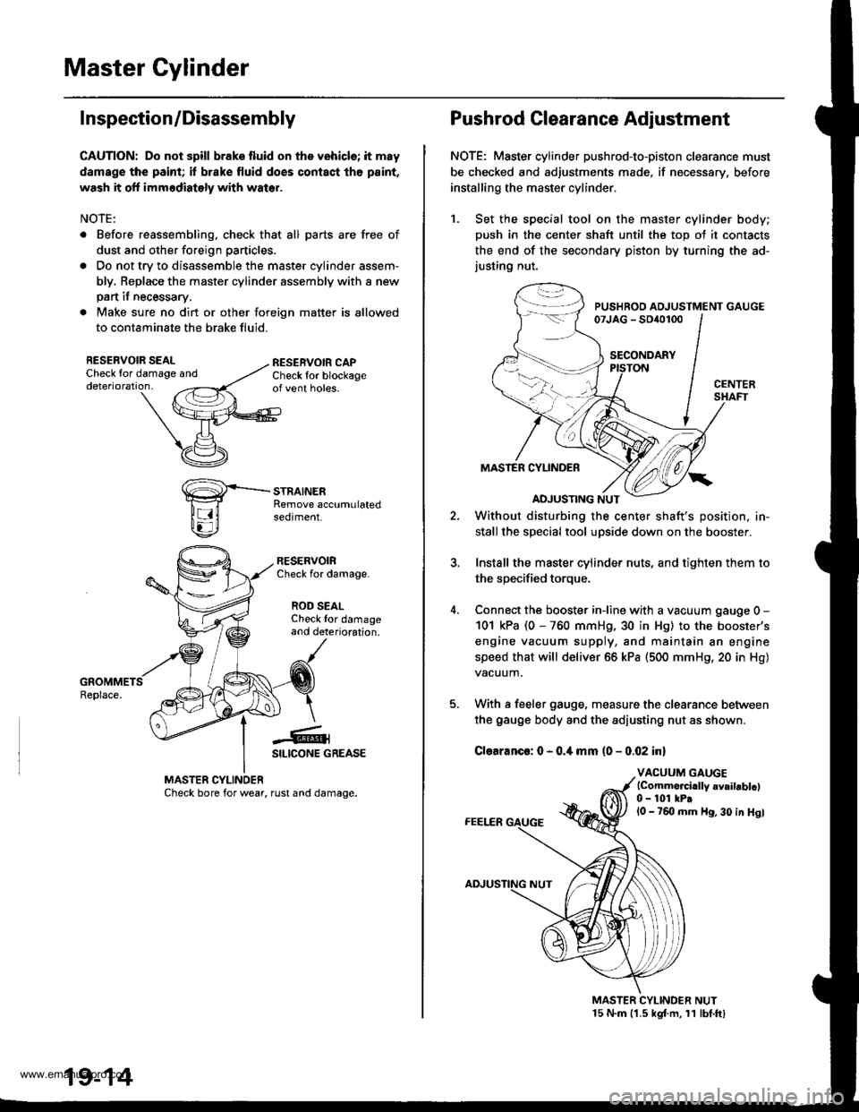
Master Cylinder
I nspection/Disassembly
CAUTION: Do not spill brake fluid onthe vehicle; it may
damsge the paint; il brake fluid does contact th6 paint.
wash it off immodiately with water.
NOTE:
. Before reassembling, check that all parts are free of
dust and other foreign particles.
. Do not try to disassemble the master cylinder assem-
bly. Replace the master cylinder assembly with a new
pan it necessary,
. Make sure no dirt or other foreign matter is allowed
to contaminate the brake fluid.
RESERVOIR SEALCheck for damaoe anddeterioration,
RESERVOIRCheck for damage.
ROD SEALCheck for damageand deterioration.
-€-1SILICONE GREASE
MASTER CYLINOERCheck bore for wear, rust and damage.
19-14
Pushrod Clearance Adjustment
NOTE: Master cylinder pushrod-to-piston clearance must
be checked and adjustments made, if necessary. before
installing the master cylinder.
1. Set the special tool on the master cylinder body;
push in the center shaft until the top ot it contacts
the end of the secondary piston by turning the ad-justing nut.
PUSHROD ADJUSTMENT GAUGE07JAG - SD{o100
SECONDARY
MASTER CYLINDER
ADJUSTING NUT
Without disturbing the center shaft's position, in-
stallthe special tool upside down on the booster.
Install the master cylinder nuts, and tighten them to
the sDecified toroue.
Connect the booster iniine with a vacuum gauge 0 -
101 kPa (0 - 760 mmHg, 30 in Hg) to the booster's
engine vacuum supply, and maintain an engine
speed that will deliver 66 kPa (500 mmH9, 20 in Hg)
vacuum.
With a feeler gauge, measure the clearance between
the gauge body and the adiusting nut as shown.
Clearanco: 0 - 0.4 mm (0 - 0.02 inl
VACUUM GAUGElCommo.cidly 6vailablcl0 - 101 kPtl0 - 760 mm Hg, 30 in Hgl
MASTER CYLINDER NUT15 N.m 11.5 kgt m, 11 lbt.ftl
www.emanualpro.com
Page 939 of 1395

6.
7.
8.
lf the clearance between the gauge body and
adjusting nut is 0.4 mm (0.02 in), the pushrod-to-
piston clearance is 0 mm. However. if the clearance
between the gauge body and adjusting nut is 0 mm,
the pushrod-to-piston clearance is 0.4 mm (0.02 in)
or more. Therefore it must be adjusted and
recheck€d.
lf clearance is incorrect, loosen the star locknut, and
turn the adjuster in or out to adjust.
. Adjust the clearance while the specified vacuum
is applied to the booster.
. Hold the clevis while adjusting.
Tighten the star locknut securely.
Remove the special tool.
0 - 0.4 mm (0 - 0.02 inl
Adjust the pushrod length as shown if the
is removed,
booster
11610.5 mm{4.6 t 0.02 inl
PUSHRODLOCKNUT1.5N.m 11.5 kgf.m. '11 lbtfl)
Install the master cylinder (see page 19-13).
9.
STAR LOCKNUT22 N.m12.2 kgt m. 16 lbtftl
10.
(Check valve is built-in)
Brake Booster Inspection
FunctionalTest
1. With the engine stopped, press the brake pedal sev-
eral times to deplete the vacuum reservoir. thenpress the pedal hard, and hold it for 15 seconds. lf
the pedal sinks, either the master cylinder is
bypassing internally, or the brake system (master
cylinder, lines, modulator, proportioning valve. or
caliper) is leaking.
2. Start the engine with the pedal pressed. lf the pedal
sinks slightly. the vacuum booster is operating nor-
mally. lf the pedal height does not vary, the booster
or check valve is faultv.
3. With the engine running, press the brake pedal light-
ly. Apply just enough pressure to hold back auto-
matic transmission creep. lf the brake pedal sinks
more than 10 mm (3/8 in.) in three minutes, the mas-
ter cylinder is faulty. A slight change in pedal height
when the Ay'C compressor cycles on and off is nor-
mal. (The Ay'C compressor load changes the vacuum
available to the booster.)
Leak Test
1.Press the brake pedal with the engine running, then
stop the engine. lf the pedal height does not vary
while pressed for 30 seconds, the vacuum booster is
OK. lf the pedal rises, the booster is faulty.
With the engine stopped, press the brake pedal sev-
eral times using normal pressure. When the pedal is
first pressed. it should be low, On consecutive appli-
cations, the pedal height should gradually rise. lf thepedal position does not vary. check the booster
check valve.
Boostor Chock Valve Test
1. Disconnect the brake booster vacuum hose at the
booster.
2. Start the engine, and let it idle. There should be vac-
uum. lf no vacuum is available, the check valve is
not working properly. Replace the brake booster
vacuum hose and check valve. and retest.
ERAKE BOOSTERVACUUM HOSE
www.emanualpro.com