Page 1167 of 1395
Dashboard
PGM.FI MAIN RELAY
BLOWER MOTOR HIGH RELAY
lwir. colorc: BLK/YEL, ILBLU/BLK, ORN/WHT,.nd BLKI
23-7
www.emanualpro.com
Page 1182 of 1395
Connector ldentification and Wire Harness Routing
Main Wire Harness {Right side of dash and floor branchesl {cont,dl
Connector or
Tsrminal
Number ol
CavitiesLocationConnects toNotes
c427
c428
c429
c430
c431
c432
c433
c434
c435
c436
c436
c447
6
26
22
7
20
5
7
25Front passenger's door
Behind right kick panel
Behind right kick panel
Behind right kick panel
Behind right kick panel
Under right side of dash
Under .ight side of dash
Under middle of dash
Under middle of dash
Under middle of dash
Under middle of dash
Behind right kick panel
Front passenger's door wire harness(c671)
Right side wire harness {C601)ABS control unit
ABS control unit
Engine wire harness (C127)
PGM-Fl main relay
JUnotron connector
Tailgate open relay
Headlights f lasher relay
Heater sub-harness (C731 )Heater sub-harness (C731)
ECM/PCM
ABS
ABS
Optional
Optional'97 model'98 - 00
models'98 - 00
mooets
G402Under right side of dashBody ground, via main wire harness
23-22
www.emanualpro.com
Page 1203 of 1395

Power Distribution
Fuse-to-Gomponent(sl Index (numerical sequence)
Under-hood Fuse/Rolay Box:
41
43
44
46
47
48
49
50
52
Capacity
'100 A
40A
7.5 A
15 A
40A
7.5 A
30A
204
204
15 A
10A
40A
40A
204
20A
Capacity
40A
204
7.5 A
wiro ColorFuseCircuit(s) Prot€cted
A
lgnition switch (BAT)
lntegrated control unit
Ceiling lights
Spotlights
PGM-Fl main relay
Not used
No. 7, 8, 10, 11 fuse in the under-dash fuse/relay box
Audio unit
Clock {'98 - 00 models)
Data link connector ('98 - 00 models)
ECM (VBU) {'98 - 00 models: M/T)
Heater control panel
PCM (VBU) (A./T)
Combination light switch (via under-dash fuse/relay box)
No. 20, 33 fuse in the under-dash fuss/relay box
Not used
Rear window defogger (via relay)
Door lock control unit
Hatch glass opener solenoid
Keyless door lock control unit ('98 - 00 models)
Horn relay
Horns (via relay)
via brake switch:
ABS control unit
Brake lights
Cruise control unit
ECM ('98 - 00 models: M/T)
High mount brake iight
PCM (4./T)
Trailer lighting connector
Turn signal/hazard relay (via switch)
Option connector (+B)
No. 6 fuse in the under-dash fuse/relay box
Blower motor (via relay)
Condenser fan motor (via relay)
Ay'C compressor clutch (via relay)
Radiator fan motor (via relay)
Wire Color Circuitls) Protoct
53
54
50
WHT/BLK
WHT/RED
WHT/BLK
WHT/BLU
WHT/BLU
WHT
WHT/GRN
WHT/GRN
WHT/GRN
WHT/BLK
WHT/RED
BLU/WHT
WHT
RED
BLK/RED
Under-hood ABS Fuss/nehy Box:
Fusg
61WHT
WHT/GRN
BRN/YEL
ABS pump motor {via relay}
ABS control unit
ABS control unit
{cont'd)
23-43
www.emanualpro.com
Page 1204 of 1395

Power Distribution
Fuse
1
3
5
6
7
I
9
10
11
12
13
14
"^
RED/B LU
RED/GRN
WHT/BLK
RED/VVHT
YEUBLK
RED
GRN/BLK
BLU/BLK
YEVBLK
YEUGRN
RED
BLK/YE L
BLK/VVHT
17
7.5 A
7.5 A
BLVBLU
BLKA/EL
18
19
20
22
7.54
7.54
l0 A
10 A
YEUBLK
YEVRED
BLKAr'YHT
RED /VHT
RED/YE L
Fuse-to-Component(sl Index (numerical sequencel (cont'dl
Under-dash Fuse/Relay Box:
Capacity
10 A
10 A
10 A
10 A
20A
204
15A
204
204
7.5 A'15 A
7.5 A
7.5 A
Wire ColorCircuit{s) Protected
Not used
Not used
Rear window washer motor (via switch)
Rear window wiper control unit ('97 model)
Rear window wiper motor
Daytime running rights resister {Canada)
Right headlight {High beam}
Daytime running rights resister (Canada)
High beam indjcator light
Left headlight (High beam)
Rear accessory socket (via relay)
Left rear power window motor (via switch)
Right rear power window motor (via switch)
Distributor (ignition control module)
Front passenger's power window motor (via switch)
Driver's power window motor {via switch)
Power window master switch (power window control unit)
Turn signal/hazard relay (via switch)
PGM-FI main relay
SRS unit (VA)
Cruise control unit (via switch)
Cruise main switch indicator light
Alternator
Charging system light
ELD unit (USA)
EVAP bypass solenoid valve ('98 - 00 models)
EVAP control canister vent shut valve ('98 - 00 models)
EVAP purge control solenoid valve
Primary HO2S
Secondary H02S
VSS
ABS control unit
Option connector (lG2)
Ay'C compressor clutch relay
Blower motor high relay
Blower motor relay
Condenser fan relay
Heater control panel
Left power mirror actuators (via switch)
Mode control motor
Radiator fan relay
Recirculation control motor
Right power mirror actuators (via switch)
Daytime running lights control unit (Canada)
Back-up lights
Reverse relay (A"/T)
Daytime running lights control unit (Canada)
Right headlight (Low beam)
Left headlight (Low beam)
23-44
www.emanualpro.com
Page 1205 of 1395

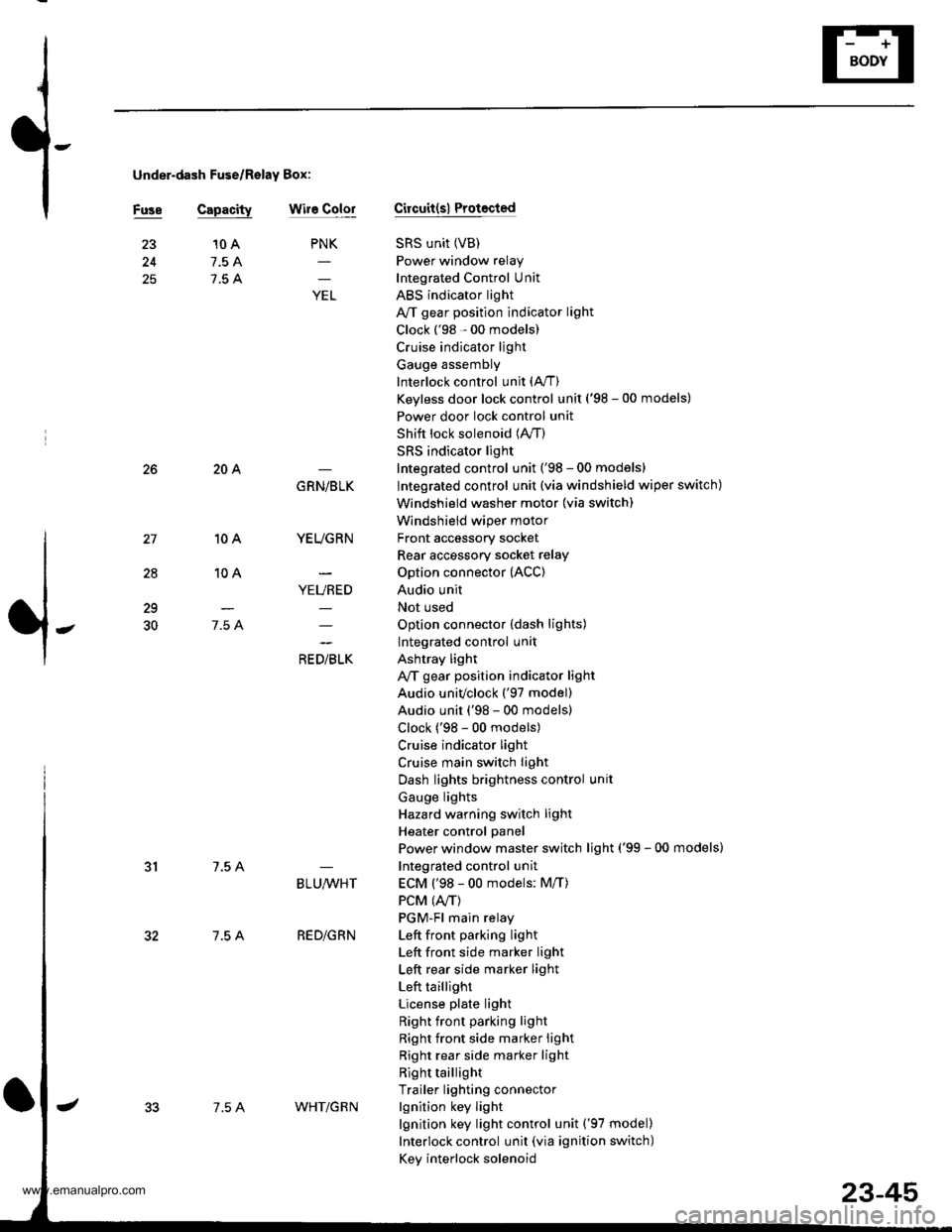
under-dash Fuse/Relay Box:
Fuse Capacitywir6 ColorCircuit(sl Protocted
SRS unit (VB)
Power window relay
Integrated Control Unit
ABS indicator light
A/T gear position indicator light
Clock ('98 - 00 models)
Cruise indicator light
Gauge assembly
Interlock control unit (A,/T)
Keyless door lock control unit ('98 - 00 models)
Power door lock control unit
Shift lock solenoid (lVT)
SRS indicator light
Integrated control unit ('98 - 00 models)
Integrated control unit (via windshield wiper switch)
Windshield washer motor (via switch)
Windshield wiper motor
Front accessory socket
Rear accessory socket relay
Option connector (ACC)
Audio unit
Not used
Option connector (dash lights)
Integrated control unit
Ashtray light
A,/T gear position indicator light
Audio univclock ('97 model)
Audio unit ('98 - 00 models)
Clock ('98 - 00 models)
Cruise indicator light
Cruise main switch light
Dash lights brightness control unit
Gauge lights
Hazard warning switch light
Heater control panel
Power window master switch light ('99 - 00 models)
Integrated control unit
ECM ('98 - 00 models: M/T)
PCM (4./T)
PGM-Fl main relay
Left front pa.king light
Left front side marker light
Left rear side marker light
Left taillight
License plate light
Right front parking light
Right front side marker light
Right rear side marker light
Right taillight
Trailer lighting connector
lgnition key light
lgnition key light control unit ('97 model)
Interlock control unit (via ignition switch)
Key interlock solenoid
25
PNK
;
10 A
7.5 A
7.5 A
28
10A
10A
7.5 A
204
7.5 A
7.5 A
GRN/BLK
YEUGRN
YEURED
a, olrL"
29
30
BLU,ryVHT
RED/GRN
7.5 AWHT/G R N
23-45
www.emanualpro.com
Page 1206 of 1395

Ground Distribution
Ground-to-Component(sl Index
GroundWire Color
G2
G3
G 10'l
G201
G202
G351
BLIVRED
BRN
BLK
BLK
BRN/BLK
BLK
BLK
BLK
23-46
Component or Circuits Grounded
Battery
Valve Cover
Transmission housing
A,/T gear position switch
ECM (PG1, PG2) ('98 - 00 models: M/T)
PCM (PG1, PG2l (Avrr)
PGM-FI main relay
Power steering pressure (PSP) switch
Radiator fan switch
VSS
Data link connector
ECM (1G1, LG2) ('98 - 00 models: M/T)
PCM (LGI, LG2) (IVT)
Shielding:
between ECM ('98 - 00 models: M/T) or PCM (Ay'T) and CKF sensorbetween ECM {'98 - 00 modets: M/T} or pCM (Ay'T) and CKp sensorbetween ECM ('98 - 00 models: M/T) or PCM (rVT) and CYP sensorbetween ECM ('98 - 00 models: M/T) or PCM (Ay'T) and TDC sensorbetween ECM {'98 - 00 models: M/T) or PCM (ly'T) and countershaft speed sensor (Ay'T)
between ECM ('98 - 00 models: M/T) or PCM {A,,/T) and mainshaft sp€ed sensor {!VT)between ECM ('98 - 00 models: M/T) or PCM (A,/T) and primary HO2Sbetween ECM ('98 - 00 models: M/T) or PCM (Ay'T) and secondary HO2SHorn (High)
Horn {Low}
Radiator fan motor
Right headlight
Right front parking light
Right front side marker light
Right front turn signal light
Condenser fan motor
Cruise actuator
Left front parking light
Left front side marker light
Left front turn signal light
Left headlight
Rear window washer motor
Windshield washer motor
ABS pump motor
www.emanualpro.com
Page 1314 of 1395

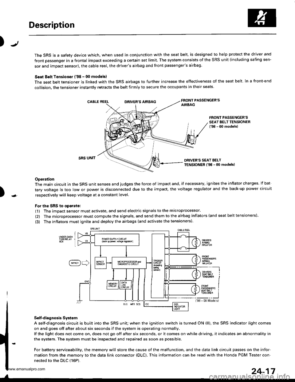
Description
J)
The SRS is a safety device which, when used in conjunction with the seat belt, is designed to help protect the driver and
front passenger in a frontal impact exceeding a certain set limit. The system consists of the SRS unit (including safing sen-
sor and impact sensor), the cable reel, the driver's airbag and front passenger's airbag.
Seat Bolt Tensioner {'98 - 00 models}
The seat belt tensioner is linked with the SRS airbags to further increase the effectiveness of the seat belt. In a front-end
collision, the tensioner instantly retracts the belt firmly to secure the occupants in their seats
FRONT PASSENGER'SAIREAGDRIVER'S AIRBAG
FRONT PASSENGER'SSEAT BELT TENSIONER{'98 - 00 modelsl
)
SRS UNITDRIVER'S SEAT BELTTENSIONER l'98 - 0O modeb)
Operation
The main circuit in the SRS unit senses and judges the force of impact and, if necessary, ignites the intlator charges. lf bat
tery voltage is too low or power is disconnected due to the impact, the voltage regulator and the back-up power circuit
respectively will keep voltage at a constant level.
For the SRS to operate:
(1) The impact sensor must activate, and send electric signals to the microprocessor.
(2) The microprocessor must compute the signals, and send them to the airbag inflators (and seat belt tensioners).
(3) The inflators must ignite and deploy the airbags (and activate the tensioners).
Selt-diagnosis System
A self-diagnosis circuit is built into the SRS uniU when the ignition switch is turned ON (ll), the SRS indicator Iight comes
on and goes off after about six seconds if the system is operating normally.
lf the light does not come on, does not go off after six seconds, or it comes on while driving, it indicates an abnormality in
the system. The system must be inspected and repaired as soon as possible.
For battery serviceability, the memory will store the cause of the malfunction, and the data link circuit passes on the infor
mation from the memory to the data link connector (DLC). This information can be read with the Honda PGM Tester con-
nected to the DLC {16P).
198
---__-l
TENSTO1En II
_-___J- 00 N4ode s)
24-17
www.emanualpro.com
Page 1315 of 1395
Circuit Diagram
UNDER.DASHFUSE/RELAYBOX
NOTE: The SRS main harness uses all GRY('97 model) or GRN ('98 - 00 models) wires.
WHT/BLK -'- WHT
DRIVEB'SAIRBAGNFLATOR
A
#+
tt tll./ d I
GRY GRY(GRN) (GRN)
FRONTPASSENGER'SALRBAGINFLAlOR
tlGRY GFY(GFN) (GRN)
DRIVER'SSEAT EELTTENSIONER
FRONTPASSENGERSSEAT BELTTENSIONEF
GRN(BLU/PNK)
BLK
G401
24-18
PCM/ECM SERVICE MEMORY ERASECHECK S GNAL (MES)CONNECTOB CONNECTOR(2P)
DATA LINXCONNECTOR(Drc) (r6P)
Models)('98 - 00
IGNITION SWITCHUNDEF,HOOD FUSE/RELAY BOX
YEUGRN
+
PGM FImam relay
SFS INDICATOR CIRCUIT(ln lhe gauge assembly)
Shill loc* so enoid
BLU
GR\
GNY GRY
H
GFY GRYlcFNt (GlN)
??
I r-?LT BLU BRN BRN
tttr?F?F
VVV
SRS NDICATORL GHT {r.4W)
5 12 4 11 | 16 17 15 I 18 I
10 14 113
U
S8S UN T TERMINALS
3567I
101114151718
Terminal side of male terminals
-4
www.emanualpro.com