Page 561 of 1395
Component Locations
ASSEMBLY
POWERTRAIN CONTROLMODULE {PCMI
COUNTERSHAFTSPEED SENSOR
AUTOMAIIC TRANSAXI.E(A/T} GEAR POSITIONswtTcH
\
CONTBOL UN]T
SHIFT CONTROLSOLEM)ID VALVEASSEMBLY
SPEED SCNSOR
14-45
www.emanualpro.com
Page 562 of 1395
PCM Circuit Diagram (A/T Control System)
'97 Model
UNDER.I]OOD FUSAFELAY BOXEATTEFY
_YEL_
T-l ,
TT-l
t_-:
G101
'Fr-r.04
P- r.-or..u L_a TMEALOC(BrK€ru -<< calTFoL
P_ *+rr
F- onmrxCFUISECONTFOLUNITf-"".>
| ["'"]
I l,[-l
III ;,
F_ pw
P_ eLu
F-- enN
UNDER DASN
M 25(7.54)
IGNITONSWITCH UNDEF OASNFUSAFELAYSOX
oowEa-qar. cor.lFo- MooLrE rpcMr F &*1 r*--'l_____O_=_ATP IO! ,ATP . ATD , A-P , A-P , A-PNP lrNo lR 101 103 12 ll
Ar'TGEAR POS]TIONswtcN
14-46
www.emanualpro.com
Page 564 of 1395

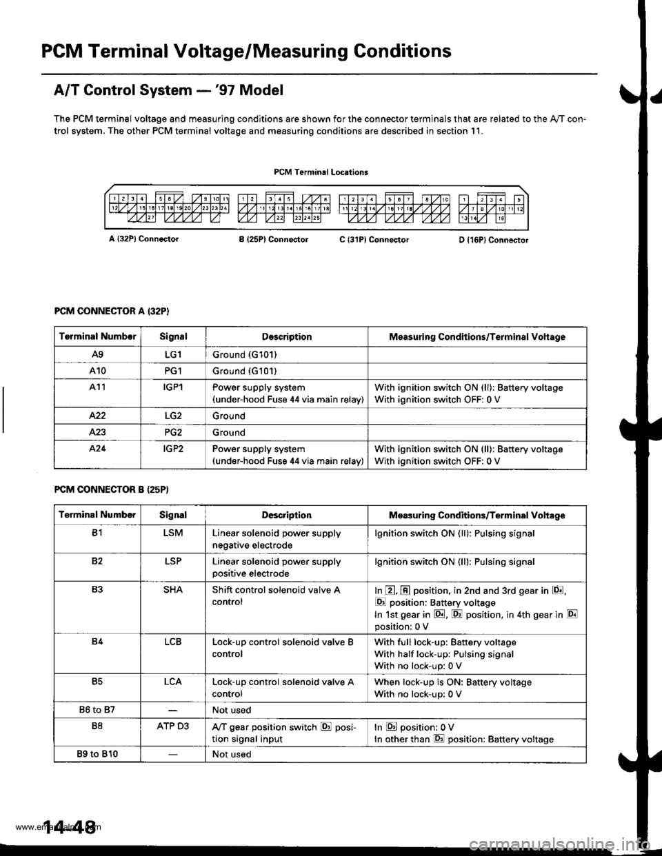
PGM Terminal Voltage/Measuring Conditions
A/T Control System -'97 Model
The PCM terminal voltage and measuring conditions are shown for the connector terminals that are related to the Ay'T con-
trol system. The other PCM terminal voltage and measuring conditions are described in section 11.
PCM Terminal Locations
A {32P} ConnectorB (25P1 ConnectolC {31PI ConnectorD {16P}Connector
PCM CONNECTOR A {32P}
FCM CONNECTOR B (25P)
Torminal NumbcrSignslDescriptionMeasuring Conditions/Terminal Vohage
A9LG1Ground (G101)
A10PG1Ground {G101)
At1IGPlPower supply system(under-hood Fuse 44 via main relav)
With ignition switch ON (ll): Battery voltage
With ignition switch OFF: 0 V
422Ground
Ground
424IG P2Power supply system(under-hood Fuse 44 via main relav)
With ignition switch ON (ll): Battery voltage
With ignition switch OFF: 0 V
Terminal NumberSignalDescriptionMeasuring Conditions/Terminal Vohage
B1LSMLinear solenoid power supply
negative electrode
lgnition switch ON (ll): Pulsing signa
82LSPLinear solenoid power supply
positive electrode
lgnition switch ON (lll: Pulsing signa
B3SHAShift control solenoid valve A
control
In @, @ position, in 2nd and 3rd gear in E,
E position: Battery voltage
In 1st gear in E. F! position, in 4th gear in E
position: 0 V
B4LCBLock-up control solenoid valve B
control
With full lock-up: Battery voltage
With half lock-up: Pulsing signal
With no lock-up: 0 V
B5LCALock-up control solenoid valve A
control
When lock-up is ON: Baftery voltage
With no lock-up: 0 V
86 to 87Not used
B8ATP D3,VT gear position switch E posi-
tion signal input
In E position: 0V
In other than E position: Battery voltage
89 to 810Not used
14-48
www.emanualpro.com
Page 565 of 1395

PCM CONNECTOR B (25P) lcont'd)
PCM CONNECTOR C {31PI
PCM CONNECTOR D II6PI
Terminal NumbelSignalDescriptionMeasuring Conditions/Terminal voltage
811SHBShift control solenoid valve B
control
In E, E position, in 1st and 2nd gear in -q,
Er position: Battery voltage
In B position, in 3rd gear in qd, q:l,in atn
gear in D. position: 0 V
812ILUlnterlock controlWhen ignition switch is ON (ll), brake pedal
deDressed and accelerator oedal released:0 V
B13D4 INDD4 Indicator light controlWhen ignition switch is first turned ON (ll): 6 V
or more for tlvo seconds
In lDll position: 6V or more
814NMSGMainshaft speed sensor ground
815NMMainshaft speed sensor signal
InpuI
Depending on engine speed: Pulsing signal
When engine is stopped: 0 V
816ATP RAy'T gear position switch Eposition signal input
In E position; OV
In other than E position: Battery voltage
817ATP 2Ay'T gear position switch E posi-
tion signal input
InEposition:0V
In other than E position: Battery voltage
B18ATP 1A/T gear position switch El posi-
tion signal input
InEposition:0V
In other than E position: Battery voltage
819 to 821Not used
B�22NCSGCountershaft speed sensor ground
NCCountershaft speed sensor signal
Inpur
Depending on vehicle speed: Pulsing signal
when vehicle is stooped: 0 V
824ATP D4A/T gear position switch iql posi-
tion signal input
In E position: 0V
In other than lgal position: Baftery voltage
825ATP NPAy'T gear position switch E and
N position signals input
In E and E positions: 0V
In otherthan @ and ffi positions:5 V
Terminal NumberSignalDescriptionMeasuring Conditions/Terminal Voltage
SCSService check signalWith ignition switch ON (ll) and service check
connector open: 5 V
With ignition switch ON (ll) and service check
connector connected with special tool: 0 V
c10VBUBack-up power system(under-hood Fuse 47)
Always battery voltage
Terminal NumberSignalDescriptionMeasuring Conditions/Terminal Voltage
STOP SWBrake switch signal inputBrake pedal pressedr Battery voltage
Brake pedal released: 0 V
14-49
www.emanualpro.com
Page 571 of 1395

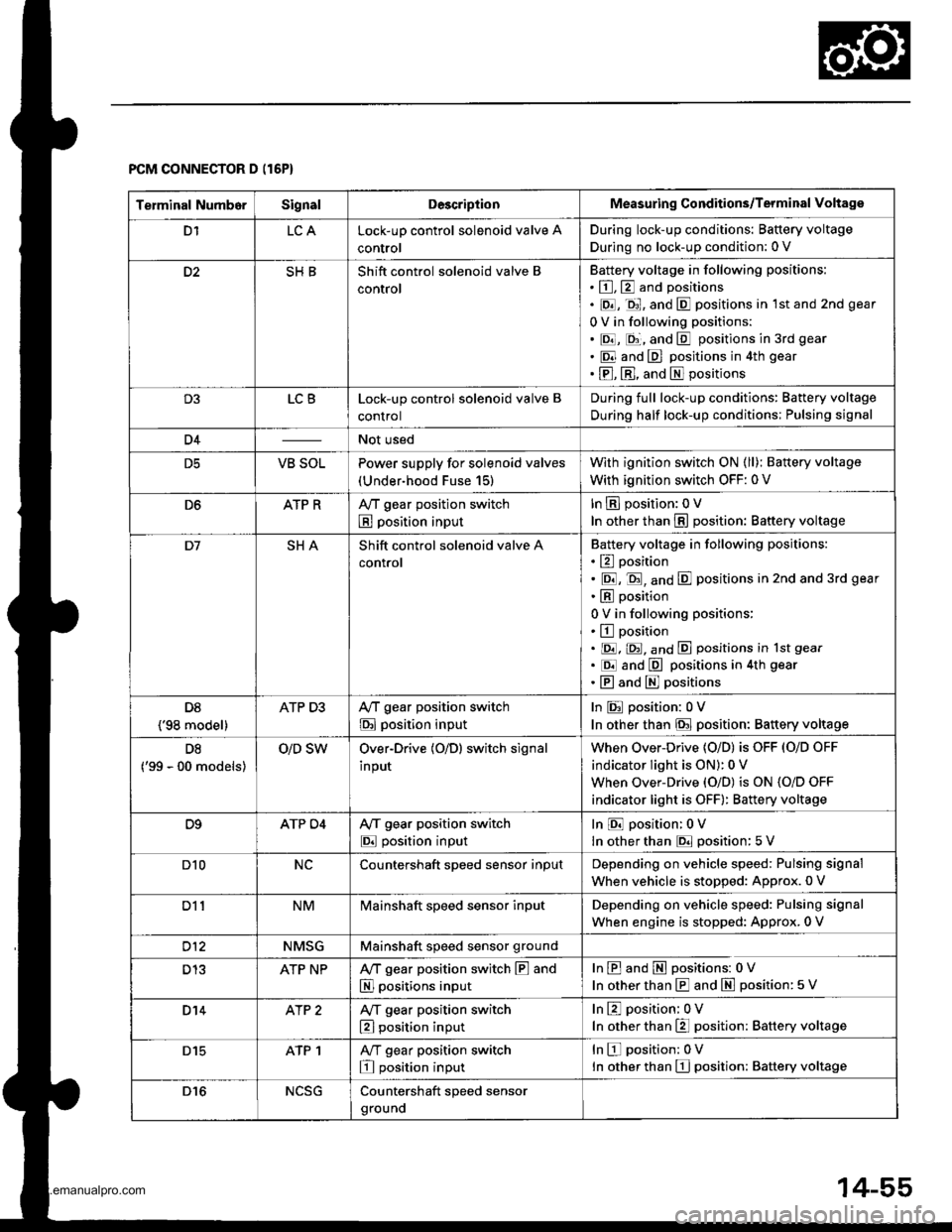
Terminal NumborSignalDescriptionMeasuring Conditions/Terminal Voltage
D1LCALock-up control solenoid valve A
control
During lock-up conditions: Baftery voltage
During no lock-up condition: 0 V
D2SHBShift control solenoid valve B
control
Battery voltage in following positions:
. E, E and positions
. E, -ql, and E positions in lst and 2nd gear
0 V in following positions:
. E, E;, and E positions in 3rd gear
. E and E positions in 4th gear
. E, El, and El positions
D3LCBLock-up control solenoid valve B
control
During full lock-up conditions: Battery voltage
During half lock-up conditions; Pulsing signal
D4Not used
D5VB SOLPower supply for solenoid valves
(Under-hood Fuse 15)
With ignition switch ON (ll); Battery voltage
With ignition switch OFF: 0 V
D6ATP RAy'T gear position switch
B position input
In E position: OV
In other than E position: Baftery voltage
D7SHAShift control solenoid valve A
control
Battery voltage in following positions:
. E position
. E, E, and E positions in 2nd and 3rd gear
. E position
0 V in following positions:
. E position. E. E, and E positions in lst gear
. Erl and E positions in 4th gear
.EandEpositions
D8
{'98 model}
ATP D3Ay'T gear position switch
E position input
In E position: 0V
In other than E position: Baftery voltage
D8
('99 - 00 models)
O/D SWOver-Drive (O/D) switch signal
input
When Over-Drive {O/D) is OFF (O/D OFF
indicator light is ON): 0 V
When Over-Drive {O/D) is ON {O/D OFF
indicator light is oFF): Battery voltage
D9ATP D4A/f gear position switch
E position input
In E position: 0V
In other than E position: 5 V
D10NCCountershaft sDeed sensor inoutDepending on vehicle speed: Pulsing signal
when vehicle is stopped: Approx.0 V
Dl1NMMainshaft speed sensor inputDepending on vehicle speed: Pulsing signal
When engine is stopped: Approx. 0 V
D12NMSGMainshaft speed sensor ground
D13ATP NPA,/T gear position switch E and
El positions input
InEandEpositions: 0V
In other than E and m position: 5 V
D14AlP 2A/T gear position switch
El position input
InE position; 0V
In other than E position: Battery voltage
D15ATP 1A,/T gear position switch
E position input
InEposition:0V
ln other than El position: Battery voltage
D16NCSGCountershaft speed sensor
grouno
PCM CONNECTOR D (16P)
14-55
www.emanualpro.com
Page 576 of 1395
Symptom-to-Component Chart
Electrical System -'97 Model
DTC*: The DTc in parentheses is the code the loa indicator right indicates when the Data LinkConnector is connected to the Honda pGM Tester.
DTC*E Indicatol
LightMILDetection ltemPage
P 1753
(1)BlinksONLock up control solenoid valve A(see page 14-64)
P1758
\21
B linksONLock-up control solenoid valve B(see page 14-66)
P 1705
(5)BlinksONA,/T gear position switch (short to ground)(see page 14-68)
P1706
(6)OFFONA,/T gear position switch {open)(see page 14-70)
P0753
\11
B linksONShift control solenoid valve A(see page 14-72)
P0758
(8)BlinksONShift control solenoid valve B(see page 14-74)
P0720
(9)BlinksONCountershaft speed sensor{see page 14-76)
P0715
(15)B linksONMainshaft speed sensor(see page l4-78)
P17 68( 16)
BlinksONLinear solenoid(see page 14-80)
P0740
{40)
OFFONLock-up control system(see page 14-82)
P0730
(41)OFFONShift control system(see page 14-84)
14-60
www.emanualpro.com
Page 578 of 1395

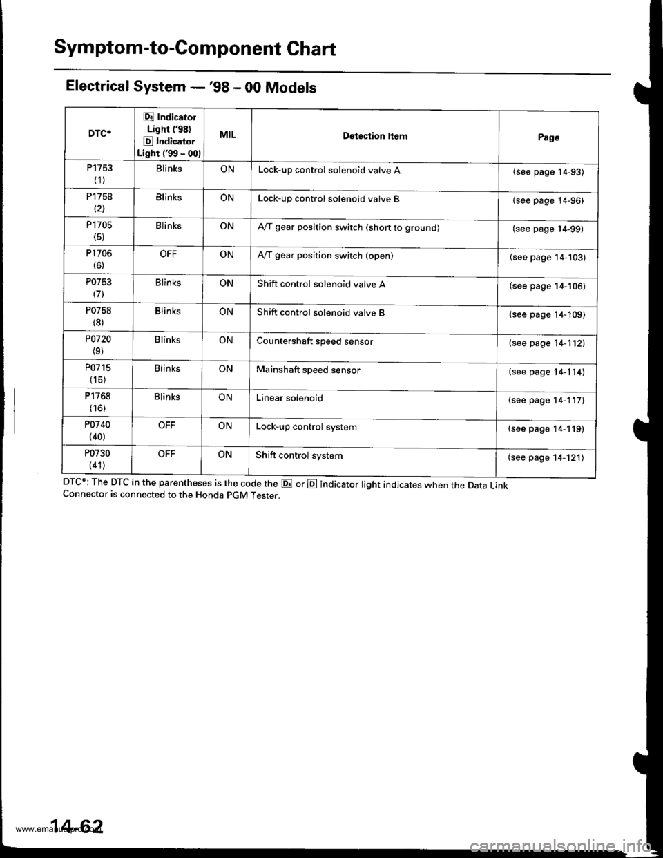
Symptom-to-Component Chart
Electrical System -'98 - 00 Models
DTC*; The DTC in the parentheses is the code the E or E indicator light indicates when the Data LinkConnector is connected to the Honda pGM Tester.
DTC*
Et Indicatol
Lighr (98)
E Indicator
Light ('99 - 00)
MILDetestion ltomPage
P1753
(1)BlinksONLock-up control solenoid valve A{see page 14-93)
P1758
(21BlinksONLock-up control solenoid valve B(see page 14-96)
P1705(5)BlinksONA,/T gear position switch (shon to grounol(see page 14-99)
P1706(6)OFFONA,/T gear position switch (open)(see page 14-103)
P0753
(71Blin ksONShift control solenoid valve A(see page 14-106)
P0758
(8)BlinksONShift control solenoid valve B(see page 14-109)
P0720
(9)BlinksONCountershaft speed sensor{see page 14-112)
P0715
{15)
BlinksONMainshaft speed sensor(see page 14-114)
P1768
(16)BlinksONLinear solenoid(see page 14-117)
POl 40(40)OFFONLock-up control system(see page 14-119)
P0730
(41)OFFONShift control system(see page 14-121)
14-62
www.emanualpro.com
Page 584 of 1395

Electrical Troubleshooting {'97 Model}
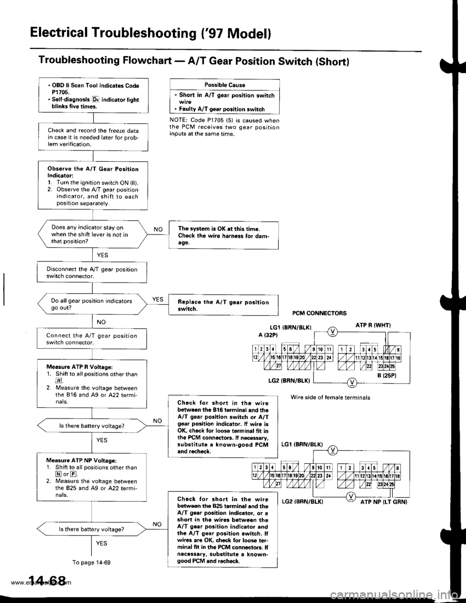
Troubfeshooting Flowchart- AIT Gear Position Switch (Short)
Po$ible Cause
' Short in A/T gear position switch
. Faulty A/T gear position switch
NOTE: Code P1705 (5) is caused whenthe PCM receives two gear positionanputs at the same time.
. OBO ll Scan Tool indicat€s CodeP1705.' Selt-diagnosis p1- indicator tightblinb Iive times.
Check and record the freeze datain case it is needed later for prob-lem verification.
Observe the A/T G€ar Po3itionIndicator:1. Turn the ignition switch ON lll).2. Observe the A./T gear positionindicator, and shilt to eachposition separately.
Does any indicator stay onwhen the shift lever is not inthat position?
The system is OK .t this time.Ch6ck ihe wii6 harness for dam-490,
Do allgear position indicatorsgo out?
Measure ATP R Voltago:1. Shitt to all positions other thantr.2. lMeasure the voltage betweenthe 816 and Ag or A22 termi-nals.Check tor 3hort in the wirebetwaen the 816torminal and thoA/T gear pGilion switch or A/Tgsar posiiion indicator. ff wire isOK, check for 10036 torminal flt inlhe PICM connectoB. It necessary,substitute a known-9ood PCMand recheck.
Measure ATP NP Voltage:1. Shift to all positions other thanNorE.2. Measure the vohage betweenlhe 825 and Ag or A22 termi-nals.Chock for ahort in the wirebetw€en tho 825 torminal end theA/T 96.r pGition indicstor, or asho.t in tha wiro! b€tween theA/T gear po3ition indicator andthe A/T g€ar position lwitch. lfwircs ar€ OK, ch6ck for loos€ ter-minal fit in the PCM connectors. Itnece3sary, substitute a known-good PCM and recheck.
ls there battery vohage?
PCM CONNECTORS
Wire side of female terminals
ATP NP {LT GRNI
14-68
To page 14-69
www.emanualpro.com