Page 675 of 1395

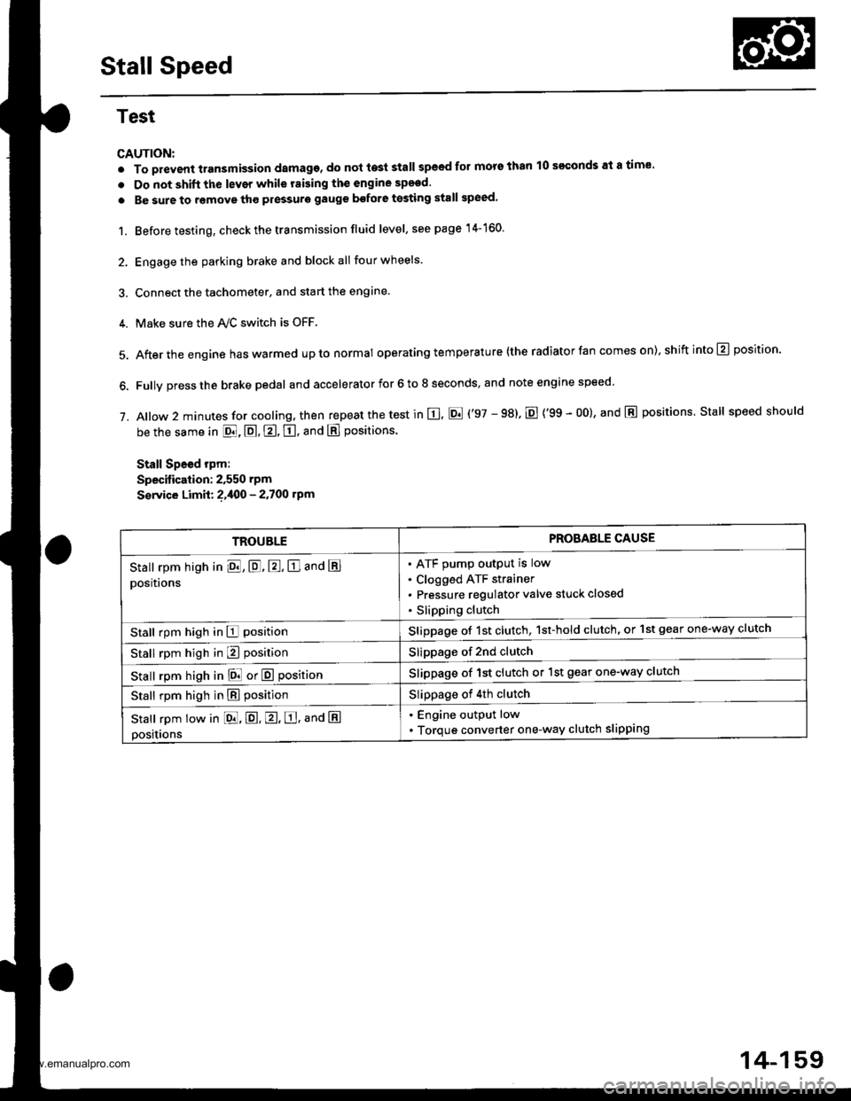
Stall Speed
Test
CAUTION:
. To prevent transmission damage, do not te3t stall speed for mors than 10 s€€onds at a time'
. Do not shift the lever while raising th€ engine spsed.
. Be sure to remove tho pressuro gauge bofore testing stall speed,
1. Before testing, check the transmission fluid level, s€e page 14-160.
2. Engage the parking brake and block all four wheels
3. Connect the tachometer, and start the engane.
4. Make sure the Ay'C switch is OFF
5. After the engine haswarmed upto normal operating temperature (the radiator fan comes on),shiftinto@ position.
6. Fully press the brake pedal and accelerator for 6 to 8 seconds, and note engine speed '
j. A|ow 2 minutes for cooling, then repeat the test in E, E ('97 - 98). E {'99 - 00}, and E positions. Stall speed should
be the same in E, E, E, tr. and E positions
Stall Speed rpm:
Specitication: 2,550 rpm
S€rvice Limit: ?,400 - 2.700 rpm
TROUBLEPROBAELE CAUSE
Stall rpm high in El, E, E, E and E
positions
ATF pump output is low
Clogged ATF strainer
Pressure regulator valve stuck closed
Slipping clutch
Stall rpm high in E positionSlippage of 1st clutch, 1st-hold clutch, or 1st gear one-way clutch
Stall rpm high in E positionSlippage of 2nd clutch
stall rpm high in E! or E positionSlippage of 1st clutch or 1st gear one-way clutch
Stall rpm high in E positionSlippage of 4th clutch
Stall rpm low in [dd, E. E, E, ana E
positions
. Engine output low
. Torque converter one-way clutch slipping
14-159
www.emanualpro.com
Page 678 of 1395

Pressure Testing
(cont'd)
Line Proslure, lst Clutch, lst.hold Clutch prsssuro Measuromont
1. Start the engine, and shift to E or @ position.
2. Run the engine at 2,000 rpm, then measure line pressure. Higher pressure may be indicated if measurements aremade in shift lever positions other than E or @ position.
shift to E ('97 - 98) or E ('99 - oo) position and hold the engine at 2.ooo rpm, then measure 1st clutch pressure.
Shift to E position and hold the engine at 2,000 rpm, then measure lst-hotd ctutch Dressure.
LOCK.UP CONTROLSOLENOID VALVEA/B ASSEMBLY
4.
PRESSURESHIFT LEVER
POSmONSYMPTOMPROBABLE CAUSEFLUID PRESSURE
StandaldService Limit
LineEor@No (or low)
line pressure
Torque converter.
ATF pump, pres-
sure regulator,
torque converter
check valve
830 - 880 kPa(8.5 * 9.0 kgflcm,,
120 - '130 psi)
780 kPa
{8.0 kgf/cm,, 'l10 psi)
1st ClutchE (97 - 98)
E ('se - oo)
No or low 1st
pressurelst Clurch
lst-hold
ClutchtrNo or low lst-
hold pressure1st-hold Clutch
14-162
www.emanualpro.com
Page 679 of 1395

znd, 3rd, and ,lth Clutch Pressurs Measuremenl'97 - 98 Modols:
1. Stan the engine, and shift to E position.
2. Run the engine at 2,000 rpm, then measure 2nd
clutch pressure.
3. Shift to E position, and hold the engine at 2'000
rpm, then measure 3rd clutch pressure.
4. Shift to E position, and hold the engine at 2,000
rpm, then measure 4th clutch pressure.
5. Shift to @ position, and hold the engine at 2,000
rpm, then measure 4th clutch pressure.
4TH CLUTCH PRESSUREINSPECTION HOLE
'99 - 00 Models:
1. Start the engine, and shift to El position.
2. Run the engine at 2,000 rpm. then measure 2nd
clutch pressure.
3. Shift to E position, and turn the Over-Drive (O/D)
OFF by pressing the O/D switch (O/O OFF indicator
light comes on).
4. Hold the engine at 2,000 rpm, then measure 3rd
clutch Pressure.
5. Turn the Over-Drive ON by pressing the O/D switch
(O/D OFF indicator light goes out), and hold the
engine at 2,000 rpm, then measure 4th clutch pres-
sure.
6. Shift to E position, and hold the engine at 2,000
rpm, then measure 4th clutch prgssure
2ND CLUTCH PRESSUREINSPECTION HOLE
3RD CLUTCH PRESSUREINSPECTION HOLE
'"r.,-ur"" "..#
- -t"1' -.
INSPECTION HOLE
PRESSURESHIFT LEVER
POSmONSYMPTOMPROBABLE CAUSE
FLUID PRESSURE
StandardServico Limit
2nd ClutchtrNo or low 2nd
pres$ure
2nd Clutch800 - 850 kPa
\A.2 - 8.1 kgtlcm2,'120 - '124 psil
760 kPa
(7.7 kgf/cm'�, 110 psi)
3rd ClutchE (97 - s8)
Elwith Over-
Drive is OFF(99 - 00)
No or low 3rd
pressure
3rd clutch
4th clutchE (97 ,98)
E (99 - oo)
No or low 4th
pressure
4th Clutch
EServo Valve or 4th
Clutch
14-163
www.emanualpro.com
Page 684 of 1395
Transfer Assembly
Installation (cont'dl
Install the exhaust pipe A.
Connect the primary heated oxygen sensor (Primary
H02S) connector,
GASKETReplace.EXHAUST PIPE A
SELF.LOCKING NUT10 x 1.25 mm54 N.m {5.5 kgf.m,40 rbf.ft)Replace.
NUT8 x 1.25 mm16Nm11.6kgf.m,12 lbf.fOReplace.
-LOCKING
SELF-LOCKING NUT8 x 1.25 mm22 N.m (2.2 kgl.m,16 rbr.fttReplace.
10. Installthe splash shield and the guard bar.
6x1.0mm9.8 N.m {1.0 kgt.m,7.2 tbt.ftt
14-168
'I '�I.
12.
Refillthe transmission with ATF (see page 14-161).
Start the engine, and run it to normal operating tem-perature (the radiator fan comes on), Turn theengine off and check ATF level.
www.emanualpro.com
Page 685 of 1395

Transmission
Removal
@
2.
'1.
Make sure lifts. iacks, and safety stands aro placed
properly, and hoist brackets are attached to the col-
rest position on the engine lsee section 11.
Apply th€ parking brake and block the r€ar wheels,
so vehicls will noi roll off the stands and fall on you
while working under it.
NOTE: Use fender covers to avoid damaging painted
surfaces.
Disconnect the negative terminal, then disconnect
the positive terminal from the battery.
Remove the intake air duct and the air cleaner hous-
ing assembly,
Remove the starter cables. Remove the harness
clamp from the clamp bracket.
5.
STARTERCABLES
Remove the transmission ground cable terminal
and the radiator hose clamp lrom the transmission
hanger.
Disconnect the lock-up control solenoid valve con-
nector, then remove the harness clamp from the
clamp bracket.HARNESS CLAMP
RADIATOR HOSECLAMP
CONTROLSOLENOID VALVECONNECTOR
CLAMP
6. Disconnect the vehicle speed sensor (VSS), the coun-
tershaft speed sensor, and the A/T gear position
switch connectors.
A/T GEAR POSITIONSWITCH CONNECTOR
VEHICLE SPEEDSENSOR |VSS'
CONNECTORBfiACKET
SPEED SENSORCONNECTOR
7. Remove the transmission housing mounting bolts.
MOUNTING BOLTS
(cont'd)
14-169
www.emanualpro.com
Page 689 of 1395
28. Place a jack under the transmission, raise it just
enough to take it off of the mounts, then remove
the transmission mount bracket.
Remove the front side transmission housino mount-
ing bolt.
29.
30. R€move the rear side transmission housing mount-
ing bolt and the rear engine mounting bolts.
Pull the transmission away from the engine until it
clears the dowel pins, then lower it on the transmis-
sion jack.
Remove thg torque converter assembly from the
transmission.
Remove the starter from the transmission housing.
31.
REAR ENGINE MOUNTING BOLTS
14-173
www.emanualpro.com
Page 775 of 1395

Transmission
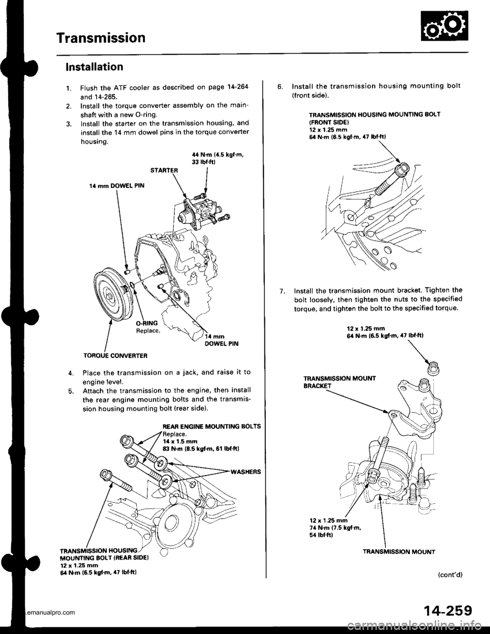
1.
lnstallation
Flush the ATF cooler as described on page 14-264
and 14-265.
Install the torque converter assembly on the main-
shaft with a new O-ring.
lnstall the starter on the transmission housing, and
install the 14 mm dowel pins in the torque converter
housing.
44 N.m {{.5 kgf.m,33 rbf.f0
Place the transmission on a jack, and raise it to
engine level.
Anach the transmission to the engine, then install
the rear engine mounting bolts and the transmis-
sion housing mounting bolt (rear sidel.
14 mm DOWEL PIN
REAR ENGINE MOUNTING BOLTS
la x 1.5 mm8:l N.m (8.5 kgf.m, 61 lbf.ftl
MOUNTING BOLT {REAR SIDEI12 x 1.25 mm6il N.m 16.5 kgd.m, 47 tbt.ttl
6. Install the transmission housing mounting bolt
(front side).
TRANSMISSION HOUSING MOUNNNG BOLT
{FRONT SIDE)12 x 1.25 mm6,1 N m (6 5 kgl m, 47 lbf'ftl
Install the transmission mount bracket. Tighten the
bolt loosely, then tighten the nuts to the specified
torque, and tighten the bolt to the specified torque.
7.
12 x 1,25 mm6,a N.ft (6.5 kgtm,47rbf.ft)
t@
TRANSMISSION MOUNTBRACKET
12 x 1 .25 mm74 N.m (7.5 kgf.m,s{ tbtftl
(cont'd)
TBANSMISSION MOUNT
14-259
www.emanualpro.com
Page 779 of 1395

26. Connect the vehicle speed sensor (VSS). the coun-
tershaft speed sensor. and the A,/T gear position
switch connectors,
VEHICLE SPEEO
SPEED SENSOACO'{NECTOR
Connect the lock-up control solenoid valve connec-
tor, then install the harness clamp on the clamp
bracket.
HARNESS CI-AMP
27.
RADIATOR HOSECLAMP
TRANSMISSIONGROUND CAB1ITERMINAL
LOCK-UP OONTROLSOLENOID VALVECONNECTOR
6x1.0mm12 N'm (1.2 kgi.m,8.? tbtftl
28.
29.
Instail the transmission ground cable terminal on
the transmission hanger, and install the radiator
hose clamp on the transmission hanger,
Connect the starter cables to the starter, and install
the harness clamD on the clamD bracket. Make sure
the crimped side of the starter cable ring terminal is
facing out.
STARTEBCABLE
STARTER CAAtf,
Install the air cleaner housing assembly and the
intake air duct.
Refill the transmission with ATF (see page 14-161).
Connect the battery positive terminal and negative
terminal.
Set the parking brake, Start the engine, and shift the
transmission through all gears three times.
Check the shift cable adjustment (see page 14-271]-.
Check the tront wheel alignment and adjust it if
needed (see section 18).
Let the engine reach normal operating temperature
(the radiator fan comes on) with the transmission in
E or N position, then turn it off and check the ATF
level {see page 14-160).
Perform a road test (see page 14-157 and 14-158).
30.
31.
34.
CLAMP BRACKET
37.
14-263
www.emanualpro.com