1999 HONDA CR-V Gear position
[x] Cancel search: Gear positionPage 891 of 1395
Power Steering Gearbox
Reassembly (cont'dl
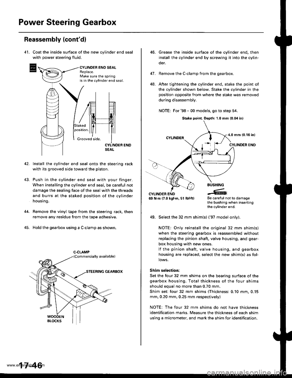
4l. Coat the inside surface of the new cvlinder end seal
with power steering fluid.
CYLINDEB ENO SEALReplace.Make sure the springis in the cylinder end seal.
43.
Stakedposrtron.
Grooved side.
42. Install the cylinder end seal onto the steering rack
with its grooved side toward the piston.
Push in the cylinder end seal with your finger.
When installing the cylinder end seal, be careful not
damage the sealing face of the seal with the threads
and burrs at the staked position of the cylinder
housing.
Remove the vinyl tape from the steering rack, then
remove any residue from the tape adhesive.
Hold the gearbox using a C-clamp as shown.
GEARBOX
44.
45.
C.CLAMP
17-46
46.Grease the inside surtace of the cylinder end, then
install the cylinder end by screwing it into the cylin-
der.
Remove the C-clamp from the gearbox.
After tightening the cylinder end, stake the point of
the cylinder shown below. Stake the cylinder in the
position opposite from where the stake was removed
during disassembly,
NOTE: For '98 - 00 models, go to step 54.
41.
48.
BUSHING
-tGCYLINDER END69 N.m (7.0 kgf.m,51 lbtft)8e careful not to damagethe bushing when insertingthe cylinder end.
49. Select the 32 mm shim(s) ('97 model onlv).
NOTE: Only reinstall the original 32 mm shim(s)
when the steering gearbox is reassembled without
replacing the pinion shaft. valve housing, and gear-
box housing with new ones.
lf the pinion shaft, valve housing, and gearbox
housing are replaced, select the new shim{s) as fol-
lows.
Shim selection:
Set the four 32 mm shims on the bearing surface of the
gearbox housing. Total thickness of the four shims
should equal no more than 0.70 mm.
Shim set: four 32 mm shims (Thickness: 0.10 mm, 0.15
mm, 0.20 mm, 0.25 mm respectively)
NOTE: The four 32 mm shims do not have thickness
identification marks. Measure the thickness of each shim
using a micrometer, and mark the shim for identification.
Stake point, Depth: 1,0 mm (0.04 inl
4.0 mm {0.16 in)
www.emanualpro.com
Page 892 of 1395
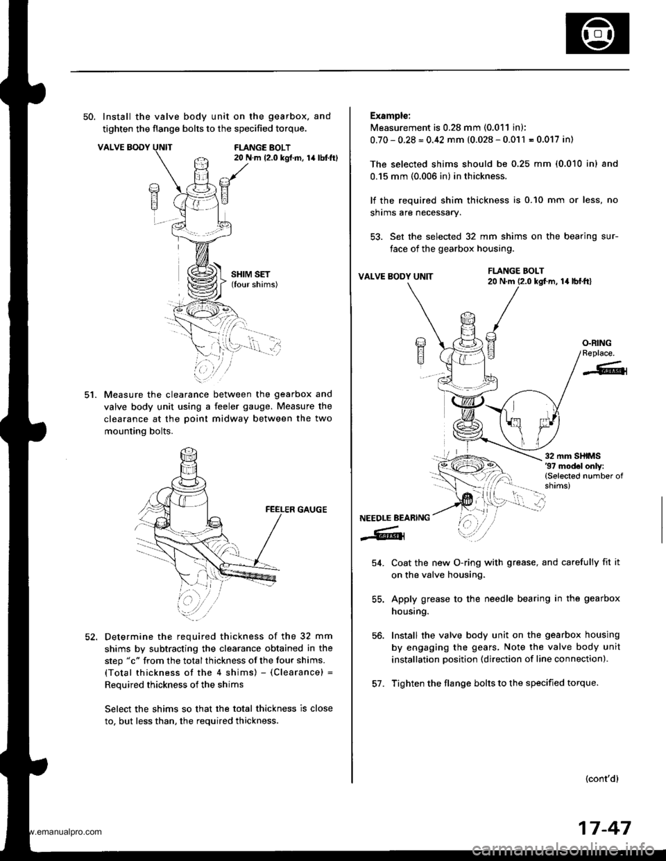
50. Install the valve body unit on the gearbox. and
tighten the flange bolts to the specified torque.
VALVE BODYFLANGE BOLT20 N.m 12.0 kgt.m, 14lbtft)
ct.
SHIM SET(four shims)
Measure the clearance between the gearbox and
valve body unit using a feeler gauge. Measure the
clearance at the poinl midway between the two
mounting bolts.
GAUGE
Determine the required thickness of the 32 mm
shims by subtracting the clearance obtained in the
step "c" from the total thickness of the four shims.
(Total thickness of the 4 shims) - (Clearance) =
Reouired thickness of the shims
Select the shims so that the total thickness is close
to, but less than, the required thickness.
Example:
Measurement is 0.28 mm (0.011 in);
0.70-0.28=0.42 mm (0.028-0.011 = 0.017 in)
The selected shims should be 0,25 mm (0.010 inl and
0.15 mm (0.006 in) in thickness.
lf the required shim thickness is 0.10 mm or less, no
shrms are necessary.
53. Set the selected 32 mm shims on the bearing sur-
face of the gearbox housing.
VALVE BODY UNITla lbl.frl
Coat the new O-ring with grease, and carefully fit it
on the valve housing.
Apply grease to the needle bearing in the gearbox
housing.
Install the valve body unit on the gearbox housing
by engaging the gears. Note the valve body unit
installation position (direction of line connection).
Tighten the flange bolts to the specified torque.
(cont'd)
FLANGE BOLT20 N.m (2.0 kgf.m,
/a)E?
E
O.RINGReplace.
-6{
NEEDLE BEARING
-6lr
54.
56.
57.
17-47
www.emanualpro.com
Page 896 of 1395
lnstallation
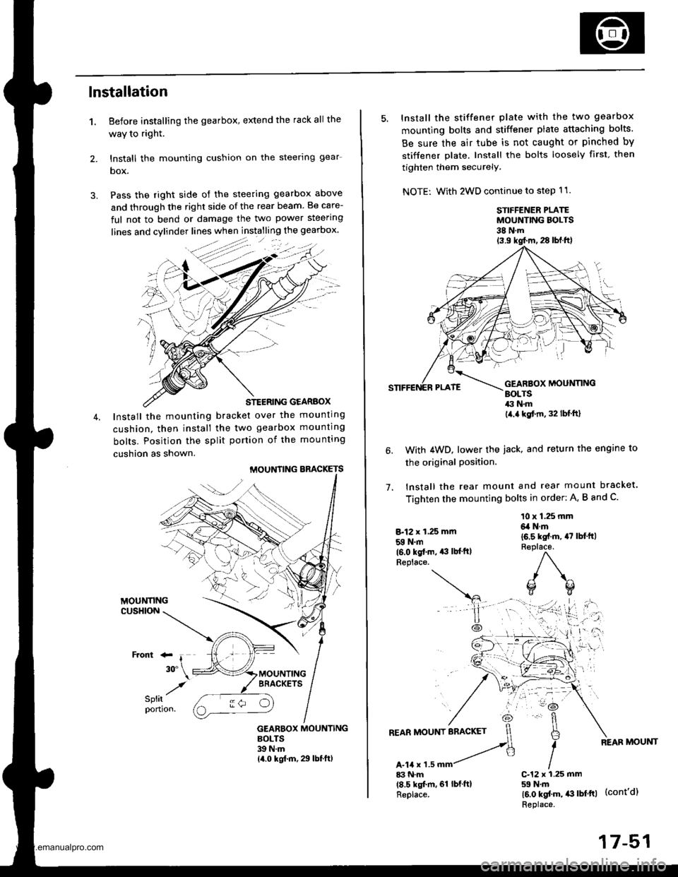
1. Before installing the gearbox, extend the rack all the
waY to right.
2. lnstall the mounting cushion on the steerlng gear-
box.
3. Pass the right side of the steering gearbox above
and through the right side of the rear beam. Be care-
ful not to bend or damage the two power steering
STEERING GEARBOX
Install the mounting bracket over the mounting
cushion. then install the two gearbox mounting
bolts. Position the split portion of the mounting
cushion as shown.
MOUNTING BBACKETS
GEARBOX MOUNTINGBOLTS39 N.m14.0 kgf.m, 29 lbf.ft)
:-
/
5. Install the stiffener plate with the two gearbox
mounting bolts and stiffener plate attaching bolts.
Be sure the air tube is not caught or pinched by
stiffener plate. Install the bolts loosely first. then
tighten them securely.
NOTE: With 2WD continue to step 11.
STIFFENER PLATEMOUNTING BOLTS38 N.m
1.
With 4WD, lower the iack, and return the engine to
the original Position.
lnstall the rear mount and rear mount bracket.
Tighten the mounting bolts in order: A, B and C.
8.12 x 1,25 mm
59 N.m(6.0 kgt.m. *l lb{'ftlReplace.
10 x 1.25 mm6,a N.m
16.5 kst.m, 47 lbl'ft)R€place.
)\^
o(]
17-51
www.emanualpro.com
Page 992 of 1395
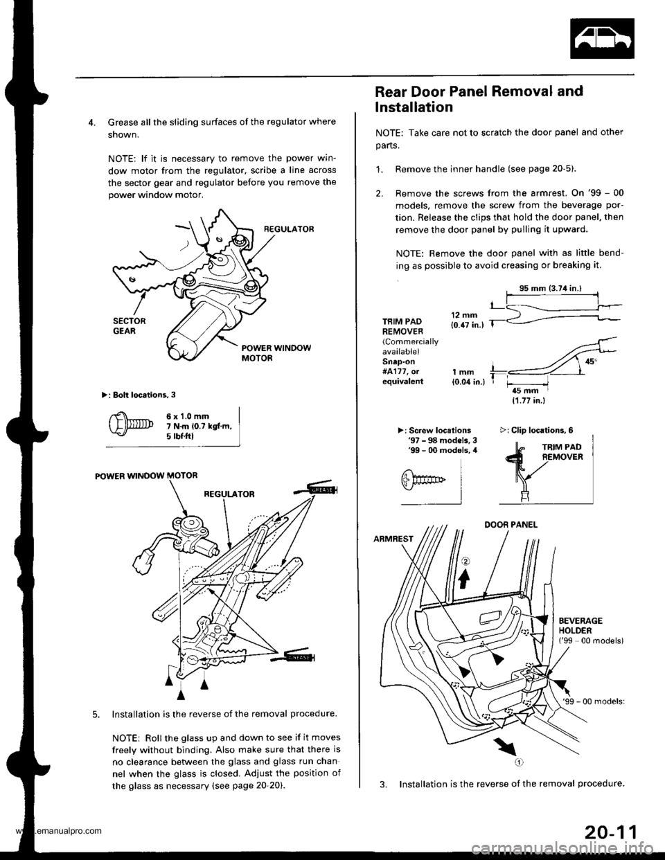
4. Grease all the sliding surfaces of the regulator where
shown.
NOTE: lf it is necessary to remove the power wrn-
dow motor from the regulator, scribe a line across
the sector gear and regulator before you remove the
power window motor.
R€GULATOF
>: Boh locations,3
6x1.0mm7 N.m lo.t kgf.m,5 tbf.ftl
POWER WINOOW MOTOR
REGULATOR
Installation is the reverse of the removal procedure.
NOTEi Rollthe glass up and down to see if it moves
freely without binding. Also make sure that there is
no clearance betlveen the glass and glass run chan
nel when the glass is closed. Adjust the position of
the glass as necessary (see page 20-20).
4
A
m^i
A
Rear Door Panel Removal and
lnstallation
NOTE: Take care not to scratch the door panel and other
parts.
1. Remove the inner handle (see page 20-5).
2. Remove the screws from the armrest. On '99 - 00
models, remove the screw from the beverage por-
tion. Release the clips that hold the door panel, then
remove the door panel by pulling it upward.
NOTE: Remove the door panel with as little bend-
ing as possible to avoid creasing or breaking it.
TBIM PADREMOVER(Commercially
available)Snap-on#4177, orequivalentlmm{0.04 in.)
>: Screw locelions'97 - 98 models. 3'99 - 00 modols, 4
11.77 in.)
DOOB PANEL
ARMREST
o
i
'99 - 00 models:
3. Installation is the reverse of the removal procedure.
\(,1
t_
T r-----/t5 mm I
EEVERAGEHOLDEN('99 00 modelsi
>i Clip locations,6
20-11
www.emanualpro.com
Page 996 of 1395
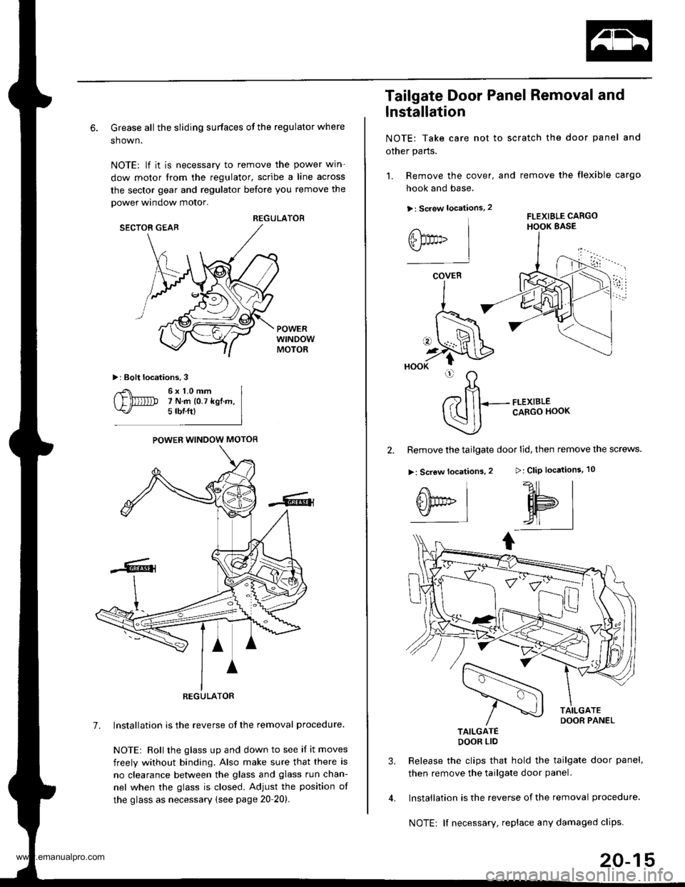
6. Grease all the sliding surfaces of the regulator where
shown.
NOTE: lf it is necessary to remove the power win-
dow motor from the regulator, scribe a line across
the sector gear and regulator before you remove the
power window motor.
REGULATORSECTOR GEAB
POWERwtNDowMOTOR
>: Bolt locations.3
6x1.0mm7 N.m 10.7 kgf.m,5 rbnftl
POWER WINDOW MOTOR
REGULATOR
7. lnstallation is the reverse of the removal procedure.
NOTEr Roll the glass up and down to see if it moves
freely without binding. Also make sure that there is
no clearance between the glass and glass run chan-
nel when the glass is closed. Adjust the position of
the glass as necessary {see page 20 20).
1. Remove the cover,
hook and base.
>: Screw locations.2
Tailgate Door Panel Removal and
lnstallation
NOTE: Take care not to scratch the door panel and
other parts.
and remove the flexible cargo
FLEXIBLE CARGOHOOK BASE
>: CliP locations.
?11 |
HPI,4| |
I
FLEXIBLECARGO HOOK
2. Remove the tailgate door lid, then remove the screws.
>: Screw locations.2
TAILGATEDOOR LIO
Release the clips that hold the tailgate door panel,
then remove the tailgate door panel.
Installation is the reverse of the removal procedure.
NOTE: lf necessary, replace any damaged clips.
3.
@t"
COVER
i
20-15
www.emanualpro.com
Page 1161 of 1395

Body Electrical
Speciaf Toofs ,...,..,.............-.23-2
Troubleshooting
Tips and Precautions ......,.,..........,.................. 23-3
Five-step Troubleshooting ........,.,.,...,,.,......... 23-5
Wire Color Codes ...,....,.. 23-5
Relay and Control Unit Locations
Engine Compartment ..,.,......,......................... 23-6
Dashboard ,.,.,..............-.- 23-7
Door ....................... .........23-10
Index to Cilcuits and Sysiems
Accessory Socket .. ,....,.,..,.,. 23-95*Airbags ................ .,....,. Sestion 24
Air Conditioning ,.,.,.... Section 22
Alternator ................... Section 4
Anti-lock Brake System {ABSI ................... Section 19'A/T Gear Position Indicator ....................... Section 1,1
Automatic Transmission System ...........,.. Section 14
Battery ................... ..............23-50
Blower Controls .,...,.,, Section 22
Charging System ....... Seqtion il
Clock -'98 Model ................ 23-98
Connector ldentification and Wire HarnessRouting .................. ......... 23.11
Cruise Control ............ Ssction 4
Dash Lights Brightness Contlo||er ..................... 23-90
Fan Conlrols ...,......,.... Section 10
Fuel Pump ,..,.,...,....,.... Section 11
Fuses...................... .,,.,.,.,.,,.,23-40*Gauges
Circuit Diagram ......-....-..23-58
Fuel Gauge .....,.,..... Section 11
Speedometer ..,..........,... 23-56
Ground Distribution ,....,.,...23-46
Hatch Glsss ODenor .........................,.,.,.,.,..,.,.,.,,. 23-121
Heater Controls .-........ Soction 21*Horns.,...,..,.,.,....... ................23"104*fgnition Switch ,,.,.,..,.,.,,.,.,.,23-51
lgnition Key Light System -'97 Mod6l .............. 23.88
-+
BODY
www.emanualpro.com
Page 1174 of 1395
![HONDA CR-V 1999 RD1-RD3 / 1.G Workshop Manual
Connector ldentification and Wire Harness Routing
Engino Wire Harness
Connecto; or
Terminal
Number of
CavitiesLocationConneqts toNotos
c101
c102
c103
c 104
c105
c105
c106
c 107
c 108
c 109
c]10
c1ll HONDA CR-V 1999 RD1-RD3 / 1.G Workshop Manual
Connector ldentification and Wire Harness Routing
Engino Wire Harness
Connecto; or
Terminal
Number of
CavitiesLocationConneqts toNotos
c101
c102
c103
c 104
c105
c105
c106
c 107
c 108
c 109
c]10
c1ll](/manual-img/13/5778/w960_5778-1173.png)
Connector ldentification and Wire Harness Routing
Engino Wire Harness
Connecto; or
Terminal
Number of
CavitiesLocationConneqts toNotos
c101
c102
c103
c 104
c105
c105
c106
c 107
c 108
c 109
c]10
c1l'l
c112
c113
c't 14
cl16
cl16
c117
c118
c119
c120
c121
c't22
c't23
c't25
cl26
cl27
cr 28
cl29
c130
c131
c132
c 133
c134
c134
c135
c 136
10
6
1
2
1
2
1
10
20
31
16
22
l0
l0'14
14
1
Left side of engine compartment
Left side of engine compartment
Middle of engine
Middle of engine
Left side of engine compartment
Left side of engine compartment
Middle of engine
Middle of engine
Middle of engine
Middle of engine
Middle of engine
Middle of engine
Middle of engine
Middle of engine
Middle of engine
Middle of engine
Middle of engine
Middle of engine
Middle of engine
Middle of engine
Middle of engine
Right side of engine
Middle of engine
Behind right kick panel
Under right side of dash
Under right side of dash
Under right side of dash
Under right side of dash
Under right side of dash
Right side of engine
Right side of engine
Middle of engine
Middle of engine
Middle of engine
Middle of engine
Middle of engine
Middle of engine
Left side of engine compartment
Middle of engine
Middle of engine
Main wire harness (C304)
Main wire harness (C305):'97 - 98 models
No. 1 fuel injector
Crankshaft speed fluctuation (CKF) sensor
Alternator
Alternator
Engine oil pressure switch
No.2 fuel injector
Evaporative emission (EVAP) purge
control solenoid valve
No. 3 fuel injector
No. 4 fuel injector
Primary heated oxygen sensor(Primary HO2S) (sensor 1)
Radiator fan switch
Coolant temperature sending unit
Engine coolant temperature (ECT) sensor
Mainshaft speed sensor
Lock-up control solenoid valve
Back-up light switch
Shift control solenoid valve
Linear solenoid valve
Countershaft speed sesnsor
Starter solenoid
Distributor
Junction connector
PCM
ECIWPCM
ECM/PCM
ECM/PCM
Main wire harness (C,|:}1)
IVT gear position switch
Vehicle speed sensor (VSS)
Throttle position (TP) sensor
MAP sensor
ldle air control (lAC)valve
lntake air temperature (lAT) sensor
Junction connector
Junction connector
Power steering pressure (PSP) switch
Junction connector
Knock sensor (KS)
A/r
USA
Canada
Alr
AlT
M/'r
Afi
'97mooel
'97 model'98 - 00
mooets
'99 - 00
models
T101
r102
Left side of en0ine companment
Right side of engine compartment
Alternator
Under-hood fuse/relay box
G101Middle of engineEngine ground, via engine wire harness
23-14
www.emanualpro.com
Page 1205 of 1395
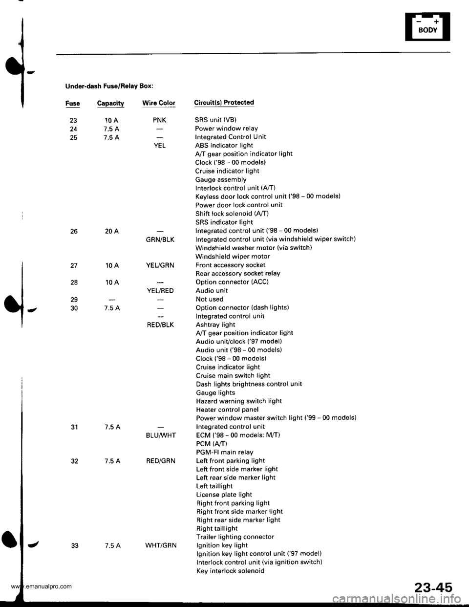
under-dash Fuse/Relay Box:
Fuse Capacitywir6 ColorCircuit(sl Protocted
SRS unit (VB)
Power window relay
Integrated Control Unit
ABS indicator light
A/T gear position indicator light
Clock ('98 - 00 models)
Cruise indicator light
Gauge assembly
Interlock control unit (A,/T)
Keyless door lock control unit ('98 - 00 models)
Power door lock control unit
Shift lock solenoid (lVT)
SRS indicator light
Integrated control unit ('98 - 00 models)
Integrated control unit (via windshield wiper switch)
Windshield washer motor (via switch)
Windshield wiper motor
Front accessory socket
Rear accessory socket relay
Option connector (ACC)
Audio unit
Not used
Option connector (dash lights)
Integrated control unit
Ashtray light
A,/T gear position indicator light
Audio univclock ('97 model)
Audio unit ('98 - 00 models)
Clock ('98 - 00 models)
Cruise indicator light
Cruise main switch light
Dash lights brightness control unit
Gauge lights
Hazard warning switch light
Heater control panel
Power window master switch light ('99 - 00 models)
Integrated control unit
ECM ('98 - 00 models: M/T)
PCM (4./T)
PGM-Fl main relay
Left front pa.king light
Left front side marker light
Left rear side marker light
Left taillight
License plate light
Right front parking light
Right front side marker light
Right rear side marker light
Right taillight
Trailer lighting connector
lgnition key light
lgnition key light control unit ('97 model)
Interlock control unit (via ignition switch)
Key interlock solenoid
25
PNK
;
10 A
7.5 A
7.5 A
28
10A
10A
7.5 A
204
7.5 A
7.5 A
GRN/BLK
YEUGRN
YEURED
a, olrL"
29
30
BLU,ryVHT
RED/GRN
7.5 AWHT/G R N
23-45
www.emanualpro.com