Page 1265 of 1395
Horn Test
1. Remove the front bumper (see section 20).
2. Disconnect the 2P connector from the horn
3, Remove the horn.
2P CONNECTOR
Test the horn by connecting battery power to one
terminal and grounding the other. The horn should
sound.
4.
HORN
23-105
5. lf the horn fails to sound, replace it
Circuit Diagram
}-BLU/FED
I
BLUi FEO BLU/RED
II
g)iirrN I
tlBLK BLK
ll
IBLK
I
I
I
G201
fl"'
LOWHORN
KEYLESSiPOWEFDOOR LOCKCONTROLUNIT
www.emanualpro.com
Page 1266 of 1395

Horns
Switch Test
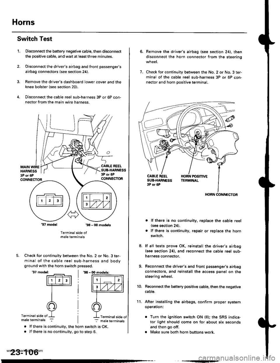
Disconnect the battery negative cable, then disconnect
the positive cable, and wait at ieastthree minutes.
Disconnect the driver's airbag and front passenger's
airbag connectors (see section 24).
Remove the drive.'s dashboard lower cover and the
knee bolster (see section 20).
Disconnect the cable reel sub-harness 3P or 6P con-
nector from the main wire harness.
1.
MAIN WIREHARNESS3P o. 6P
CABI.I REELSUB.HARNESS3P or 6PCONNECTORCONNECTOR
37 modol ,98 - 0O modots
Terminal side ofmale terminals
Check for continuity between the No. 2 or No. 3 ter-
minal of the cable reel sub-harness and bodyground with the horn switch pressed.
'97 model:'98 - (X) modols:
Terminalside of
. lf there is continuity. the horn switch is OK.. lf there is no continuity, go to step 6.
23-106
Terminal side of
6.Remove the driver's airbag (see section 241, then
disconnect the horn connector from the steerinq
wneet.
Check for continuity between the No. 2 or No. 3 ter-
minal of the cable reel sub-harness 3P or 6P con-
nector and horn Dositive terminal.
lf there is no continuity, replace the cable reel(see section 24).
lf there is continuity. repair or replace the horn
switch.
lf sll tests prove OK, reinstall the driver's airbag(see section 24), and reconnect the cable reel sub-
harness connector.
Reconnect the driver's and front passenger's airbag
connectors, and reinstall the access panel on the
steering wheel.
Reconnect the battery positive cable, then the negative
cable.
After installing the airbags, confirm proper system
operatron:
. Turn the ignition switch ON (ll); the SRS indica-
tor light should come on for about six seconds
and then go off.
. Make sure both horn buttons work.
7.
11.
8.
9.
10.
HORN CONNECTOR
www.emanualpro.com
Page 1268 of 1395

Power Mirrors
Function Test
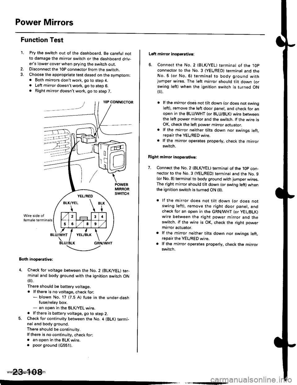
1.Pry the switch out of the dashboard. Be careful notto damage the mirror switch or the dashboard driv-er's lower cover when prying the switch out.Disconnect the 10P connector from the switch.Choose the appropriate test dased on the symptom:. Both mirrors don't work, go to step 4.. Left mirror doesn't work, go to step 6.. Right mirror doesn't work, go to step 7.
Both inoperative:
4. Check for voltage between the No. 2 (BLVYEL) ter-minal and body ground with the ignition switch ON
fl r).
There should be baftery voltage,. lf there is no voltage, check for:- blown No. 17 (7.5 A) fuse in the under-dashfuse/relay box.- an open in the BLK,/YEL wire.. lf there is battery voltage, go to step 2.5. Check for continuity between the No. 4 {BLK) termi-nal and body ground.
There should be continuity.
lf there is no continuity, check for;. an open in the BLK wire.. poor ground (c551).
,
-.t-..------'-
23-108
Left mirror inoperative:
6. Connect the No. 2 {BLKI/EL) terminal of the ,l0p
connector to the No. 3 (YEUREDI terminal and theNo.5 (or No.6) terminal to body ground withjumper wires. The left mirror should tilt down (or
swing left) when the ignition switch is turned ON t).
lf the mirror doei not tilt down (or does not swingleft), remove the left door panel, and check for anopen in the BLUMHT (or BLU/BLK) wire betweenthe left power mirror and the switch. lf the wire isOK, check the left power mirror actuator,
lf the mirror neither tilts down nor swings left,repair the YEURED wire.
lf the mirror operates properly, check the mirrorswitch.
Right mirror inoperaiiva:
7. Connect the No. 2 {BLVYEL) terminat of the 1Op con-nector to the No. 3 (YEURED) terminal and the No. 9(or No. 8) terminal to body ground with jumper wires.The right mirror should tilt down (or swing left) whenthe ignition switch is turned ON l).
. lf the mirror does not tilt down (or does notswing left), remove the right door panel, andcheck for an open in the GRN,4TVHT (or yEUBLK)
wire between the right power mirror and theswitch. lf the wire is OK, check the right power
mtrror actuator.
. lf the mirror neither tilts down nor swings left.repair the YEURED wire.. lf the mirror operates properly, check the mirrorswitch.
www.emanualpro.com
Page 1269 of 1395
J-
Switch Test
1. Remove the switch as described in Function Test
{see page 23-108).
2. Check Jor continuity between the terminals in each
switch position according to the table.
POWER MIRRORswtTcH
Teminal
t*t* \
2345b8I
L
UPoooo
DOWNoooo
LEFTo.ooo
RIGHToooo
R
UPoooo
DOWNoooo
oooo
RIGHToooo
23-109
Actuator Test
1. Prv out the mirror mount cover (see section 20).
2. Disconnect the 8P connector from the power mirror.
Check actuator operation by connecting power and
ground according to the table.
MIRROR MOUtrlTCOVER
Terminal
;;,i". -\18
TILT UP@
TILT DOWN@
SWING LEFTo@
SWING RIGHT@o
www.emanualpro.com
Page 1272 of 1395

Rear Window Defogger
Function Test
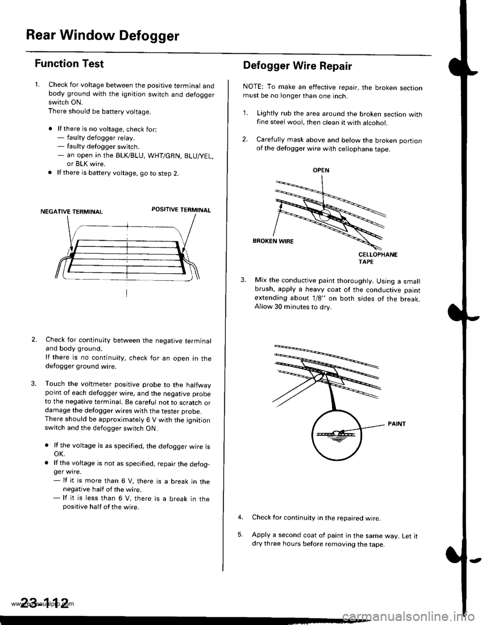
1. Check for voltage between the positive terminal andbody ground with the ignition switch and defoggerswitch ON.
There should be battery voltage.
. lf there is no voltage. check for:- faulty defogger relay.- faulty defogger switch.- an open ,n the BLK/BLU, WHT/GRN, BLU/YEL,
or BLK wire.
. lf there is battery voltage, go to step 2.
POSITIVE TERMINAL
Check for continuity between the negative terminaland body ground.
lf there is no continuity, check for an open in thedefogger ground wire.
Touch the voltmeter positive probe to the halfwaypoint of each defogger wire, and the negative probe
to the negative terminal. Be careful not to scratch ordamage the defogger wires with the tester probe.There should be approximately 6 V with the ignitionswitch and the defogger switch ON.
. lf the voltage is as specified, the defogger wire isoK.
. lf the voltage is not as specified, repair the defog-ger wire.- lf it is more than 6 V, there is a break in thenegative half of the wire.- lf it is less than 6 V, there is a break in thepositive half of the wire.
23-112
Defogger Wire Repair
NOTE: To make an effective repair, the broken sectionmust be no longer than one inch.
1. Lightly rub the area around the broken section withfine steel wool, then clean it with alcohol.
2. Carefully mask above and below the broken portionof the defogger wire with cellophane tape.
CELLOPHANETAPE
Mix the conductive paint thoroughly. Using a smallbrush, apply a heavy coat of the conductive paint
extending about 1/8" on both sides of the break.Allow 30 minutes to dry.
Check for continuity in the repaired wire.
Apply a second coat of paint in the same way. Let itdry three hours before removing the tape.
5,
OPEN
www.emanualpro.com
Page 1273 of 1395
Switch Input Test
NOTE: Before testing, check for blown No. 17 (7.5 A)
fuse in the under-dash fuse/relay box.
1. Remove the center panel {see section 20).
REAR WINOOW DEFOGGER SWITCHlin the heater control oanel)CENTER PANEL
Check for voltage between the 84 and 87 terminals
in each switch position when battery power is con-
nected to the B l terminal.
OFFless than 0.4 V
ONbaftery voltage
Ol-
I
-
23-113
www.emanualpro.com
Page 1274 of 1395
Wipers/Washers
Component Location Index
SRS components are located in this area. Review the SRs component locations, precautions, and procedures in the s6ssection (24) before performing repairs or service.
REAB WINDOW WIPER MOTOBT€st, page 23-120WPSR/WASHER SWITCHTest. page 23- l't9
REAR WINDOW WIPERCONTROL UNlT 137 mod.llInput test. page 23-118
WINDSHIELD WIPER MOTORTost, page 23-119
UNDER.DASH FUSE/RELA
INTERMITTENT W|PEN RELAYCIBCUIT, REAR WINDOW INTERMTNENTwlPER RELAY CIBCUIT l'98 - 0O mod.t.lBOX (ln the integrated control unit)Input test, page 23-68
23-114
-
n
tff
www.emanualpro.com
Page 1278 of 1395

Wipers/Washers
Rear Window Wiper Gontrol Unit lnput Test -'97 Model
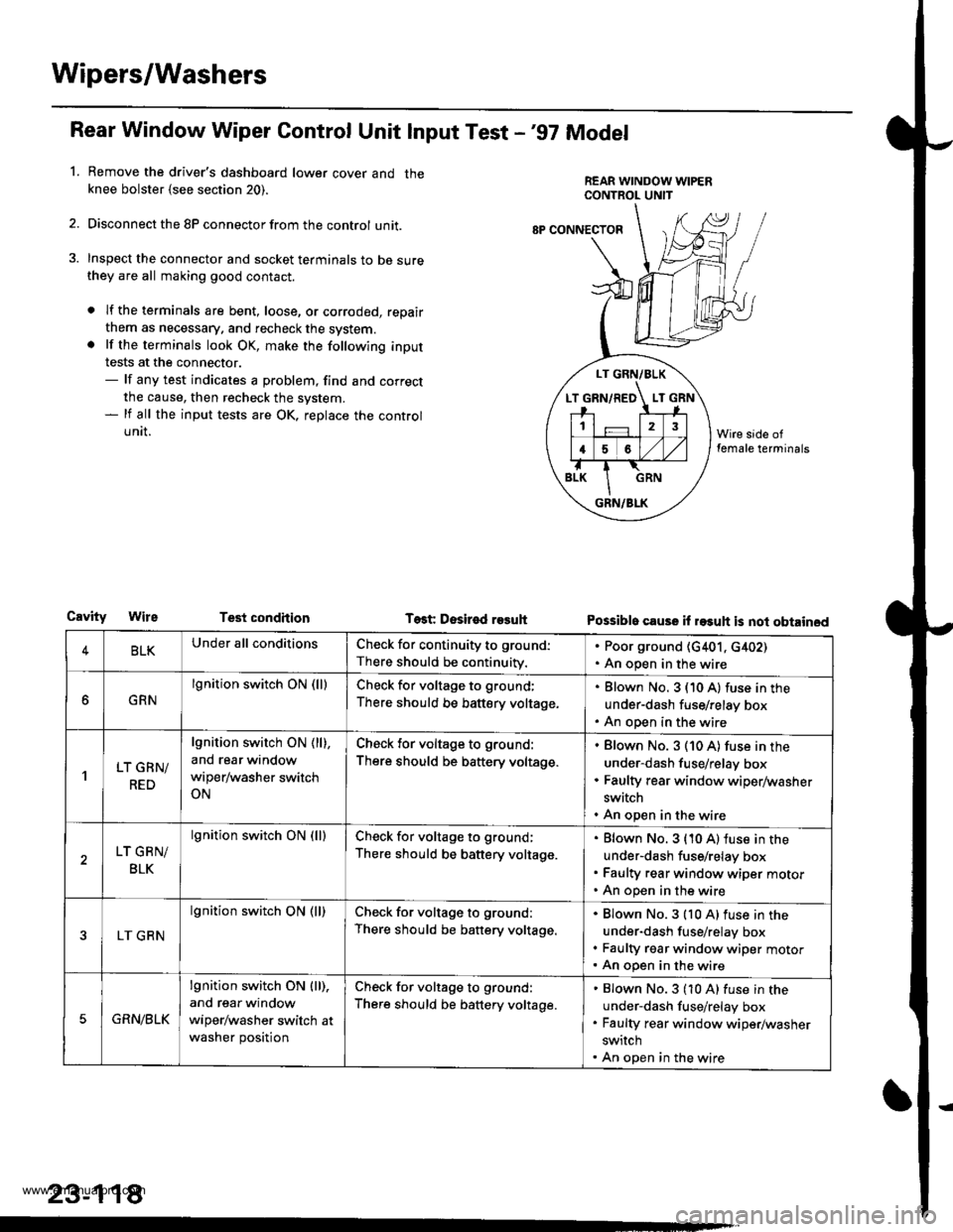
Remove the driver's dashboard lower cover and theknee bolster {see section 20).
Disconnect the 8P connector from the control unit.
Inspect the connector and socket terminals to be surethey are all making good contact.
a lf the terminals are bent, loose, or corroded, repair
them as necessary. and recheck the system.. lf the terminals look OK, make the following input
tests at the connector.- lf any test indicates a problem, find and correct
the cause, then recheck the system.- lf all the input tests are OK, replace the control
UNII.
1.
LT GRN/BLK
T GRN/RED LT
12
16
GRN/BLK
8P CONNECTOF
CavityTest condhion Test Desir€d r93uhPossible cause il rasuh is not obtained
4BLKUnder all conditionsCheck for continuity to ground:
There should be continuity.
. Poor ground (G401, c402). An open in the wire
GRN
lgnition switch ON (lllCheck for voltage to ground;
There should be battery voltage.
Blown No. 3 (10 A) fuse in the
under-dash fuse/relay box
An open in the wire
'lLT GRN/
RED
lgnition switch ON ( ll),
and rear window
wiper/washer switch
ON
Check for voltage to ground:
There should be battery voltage.
Blown No. 3 (10 A) fuse in the
under-dash fuse/relay box
Faulty rear window wiper/washer
switch
An open in the wire
LT GRN/
BLK
lgnition switch ON (lllCheck for voltage to ground;
There should be battery voltage.
Blown No. 3 {10 A) fuse in the
under-dash fuse/relay box
Faulty rear window wiper motor
An open in the wire
LT GRN
lgnition switch ON (ll)Check for voltage to ground:
There should be battery voltage.
Blown No.3 {10 A)fuse in the
under-dash fuse/relay box
Faulty rgar window wiper motorAn open in the wire
5GRN/BLK
lgnition switch ON lll),
and rear window
wiper/washer switch at
washer position
Check for voltage to ground:
There should be battery voltage.
Blown No.3 (10 A) fuse in the
under-dash fuse/relay box
Faulty rear window wiper/washer
switch
An open in the wire
23-118
www.emanualpro.com