Page 59 of 2189

Standards and ServiceLimits
Section '14Automatic Transmission (cont'd)
UO
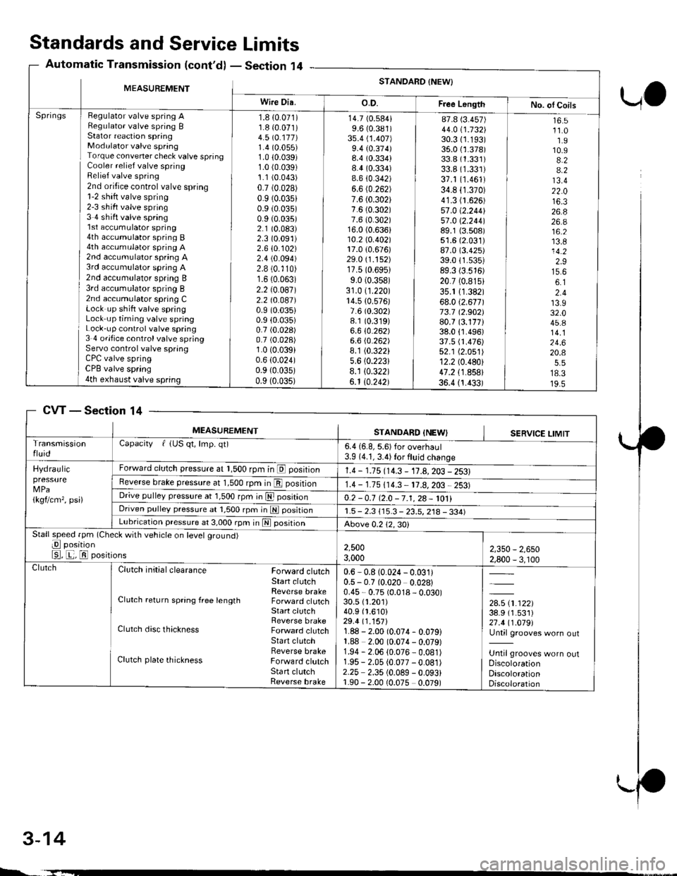
MEASUREMENTSTANDARD {NEW}
Wire Dia.o.D.Free LongthNo. ol CoilsHegulator valve spring ARegulato. valve spring BStator reaction springModulator valve springTorque convener check valve springCooler relief valve springRelief valve spring2nd oritice control valve spring1-2 shift valve spring2-3 sh ift valve spring3 4 shift valve spring'l st accumulator spring4th accumulator spring B4th accumulator spring A2nd accumulator spring A3rd accumulator spring A2nd accumulator spring B3rd acc!mulator spring B2nd accumulator spring CLock up shift valve springLock up timing valve springLock-up control valve spring3 4 ofifice control valve springServo control valve springCPC valve springCPB valve spring4th exhaust valve spring
Springs1.8 {0.071)1.8 {0.071)4.5 \O.117)1.4 (0.055)
1.0 10.039)1.0 (0.039)
1.1 (0.043)
0.7 (0.028)
0.9 (0.035)
0.9 (0.035)
0.9 (0.035)
2.1 (0.083)
2.3 (0.091)
2.610.102)2.4 (0.094)
2.8 (0.'110)
1.6 (0.063)
2.2 (0.087)
2.2 t0.041)0.9 (0.035)
0.9 (0.035)
0.7 (0.028)
0.7 (0.028)
1.0 (0.039)
0.6 (0.024)
0.9 {0.035)0.9 (0.035)
14.7 (0.584)
9.6 (0.381)
3s.4 (1.407)
9.4 (0.374)8.4 (0.334)
8.4 (0.334)
8.6 {0.342)6.6 (0.262)
7.6 (0.302)
7.6 (0.302)
7.6 (0.302)16.0 (0.636)10.2lo.402l17.0 {0.676)29.0 (1.152)
17.5 (0.6951
9.0 (0.358)
31.0 (1.220)
14.5 {0.576)7.6 (0.302)
8.1 (0.319)
6.610.262)6.6 (0.262)
8.1 (0.322)
5.6 (0.2231
8.1 10.322)6.1 10.242)
87.8 (3.457)
44.0 i.732l'30.3 (1.193)
35.0 {1.378)33.8 (1.331)
33.8 (1.331)
37.1 (1.461)
34.8 (1.370)
41.3 (1.626)
57.0 (2.2441
51 .0 \2.244189.1 {3.508)51.6 (2.031)
87.0 (3.425)
39.011.535)89.3 (3.516)
20.7 (0.815)
35.1 11.382)68.012.671173.7 12.902)80.7 (3.177)38.0 {1.496)37.5 fi.476)52.1 (2.051)
12.2 (0.480)
47.2 {1.858}36.4 {1.433)
16.511.01.910.94.24.213.422.016.326.826.a16.213.814.22.915.66.12.413.932.045.814.124.620.4
18.319.5
CVTSection 14
3-14
MEASUREMENTSTANDARD INEWISERVICE LIMITTransmissionfluidCapacity f {US qt, lmp. qt)6.4 {6.8, 5.6) for overhaul3.9 (4.1, 3.4) for fluid change
Hydraulicpressure
1kgflcm,, psi)
Forward clutch pressure at 1,500 rpm in E position1.4 - 1.15 114.3 - 11.A,203 - 2531Reverse brake pressure at 1,500 rpm in E position1.4 - 1.75 (14.3 11.8,203 2531Dr;ve pulley pressure at 1,500 rpm in E posrtrono.2 -0.7 12.0 -7.1,28- 1011Driven pulley pressure at 1,500 rpm in N positionr.5 - 2.3 115.3 - 23.5, 218 - 334)Lubrication pressure at 3,000 rpm in E posrtronAbove 0.212,30)Stall speed fpm (Check with vehicle on level ground)
E position
E, E, El positions2,5003,0002,350 - 2,6502,800 - 3, r00ClutchClutch initial clearance Forward clutchStart clutchReverse brakeClutch return spring free length Forward clutchStart clutchReverse brakeClutch disc thickness Forward clutchStart clutchReverse brakeClutch plate thickness Forward clutchSta rt clutchReverse brake
0.6 - 0.8 (0.024 - 0.031)0.5 - 0.7 (0.020 0.028)0.45 - 0.75 (0.018 - 0.030)30.5 {1.201)40.9 (1.610)
29.4 (1.157)
1.88 - 2.00 (0.074- 0.079)1.88 2.00 (0.074 - 0.079)1.94 - 2.06 (0.076 - 0.081)1.95 - 2.05 (0.077 -0.081)
2.25 2.35 (0.089 - 0.093)1.90 - 2.00 (0.075 0.079)
,*x.ar}38.9 (1.531)
27.411.019l'Until grooves worn out
Until grooves worn outDiscolorationDiscolorationDiscoloration
L.
Page 94 of 2189
Engine
Engine Removal/lnstallation ................ 5-1
Gylinder Head/Valve Train ................... 6-1
Engine Bfock .......... ...........7-1
Engine Lubrication ........... 8-1
Intake Manifold/Exhaust System ........ 9'1
Cooling ......... 10-1
Page 102 of 2189
Engine Removal/lnstallation
Removal(cont'dl
29. Remove the Ay'C compressor.
NOTE: Do not disconnect the Ay'C hoses.
30.
8x 1.25 mm A/C COMPRESSOR24 N.m (2.{ kgf.m, t7 tbtft}
Remove the shift cable (IVT).
NOTE:
. Take care not to bend the cable when removingit. Always replace any kinked cable with a newone.
. Adjust the shift cable when installing (see sec_tion 14).
8 x 1.25 mm22 N.m (2.2 kgf.m, 16 lbf.frl
LOCK WASHERBeplace.6x1.0mm14 N.m (1.4 kgf.m, tO tbtft)
5-8
A/C COMPRESSOR
t
{
31. Remove exhaust pipe A.
Dl6Y5. D16Y7 engines:
8 x 1.25 mm22 N.m 12.2 ksl.m. 16 tbI.fr)Replace.
SELF.LOCKING8 x 1.25 mm16 N.m (1.6 kgtm,12 tbt.ftlReplace.
D16Y8 ongin6;
8 x 1.25 mm22 N.m (2.2 kgf.m. 16 tbf.ftlReplace.
GASKETReplace.
SELF.LOCKING NUT10 x 1.25 mm33 N.m {3.4 kgt.m,25 lbr'frlReplace.
SELF.LOCKING NUT8 x 1.25 mm16 N.m 11.6 kgf.m, 12 lbtft)Replace.
SELF-LOCKING NUTl0 x 1.25 mm54 N.m (5.5 kgf.m, 40 lbf.ft)Replace.
Page 123 of 2189

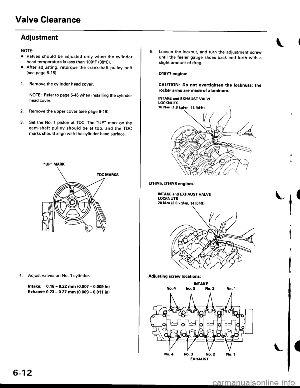
Valve Clearance
Adjustment
NOTE:
. Valves should be adjusted only when the cylindsrhead temperature is less than 100"F (38"C).
. After adjusting, retorque the crankshaft pulley bolt(see page 6-16).
1, Remove the cylinder head cover.
NOTE; Refer to page e46 when installing the cytinderhead cover.
2. Remove the upper cover (see page 6-19).
3. Set the No. 1 piston at TDC. The "UP" mark on the
cam-shaft pulley should be at top, and the TDC
marks should align with the cylinder head surface.
TDC MARKS
4. Adjust valves on No, 1 cylinder.
Intako: 0.18 - 0.22 mm {0.007 - 0.009 in}
Exhaust: 0.23 - 0.27 mm (0.009 - 0.011 inl
"UP" MARK
6-12
No.4
5. Loosen the locknut, and turn the adjustment screwuntil the feeler gauge slides back and forth with asliOht amount of drag,
D16Y7 engin.:
CAUTION: Do not oyertighlen the locknuts; thorockor arms are made of aluminum.
INTAKE end EXHAUST VALVELOCKNUTS
Dl6Y5, Dl6Y8 engin€3:
INTAKE .nd EXHAUST VALVELOCKNUTS20 N.m 12.0 kstm, 14lbtft)
Adiusting screw locations:
IMTAKEo.4 1{o. 3 No. 2
tr'
(
nb.3 No.2 No. 1EXHAUST
18 N.m (1.8 kgI.m, 13 tbl.ftl
Page 124 of 2189
6. Tighten the locknut, and check the clearance again.
Repeat the adjustment if necessary.
GAUGE
7.Rotate the crankshaft 180' counterclockwise (cam-
shaft oullev turns 90'1. The "UP" mark should be on
the exhaust side. Adjust valves on No. 3 cylinder.
"UP- MARK
t
8. Rotate the crankshaft '180' counterclockwise to
bring No.4 piston to TDC. Both TDC grooves are
once again visible. Adjust valves on No. 4 cylinder.
Rotate the crankshaft 180'counterclockwise to bring
No. 2 piston to TDC. The "UP" mark should be on
the intake side. Adjust valves on No. 2 cylinder.
-UP'MARK
6-13
Page 126 of 2189

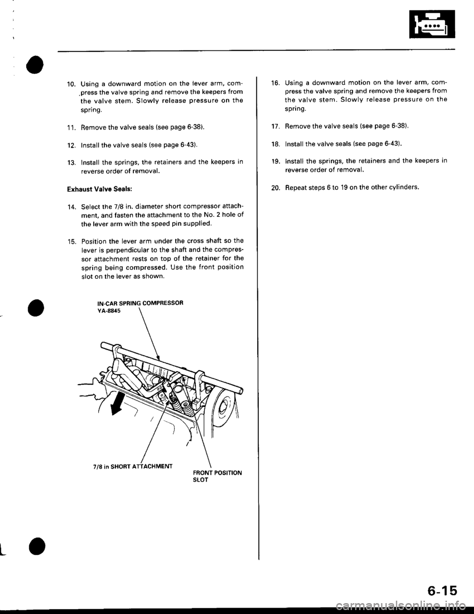
10. Using a downward motion on the lever arm, com-
.press the valve spring and remove the keepers from
the valve stem. Slowly release pressure on the
spring.
11. Remove the valve seals (see page 6-38).
12. Install the valve seals {see page 6-43).
13. Install the springs, the retainers and the keepers in
reverse order of removal.
Exhaust Valvs Sesls:
Select the 7/8 in. diameter short compressor attach-
ment, and fasten the attachment to the No. 2 hole of
the lever arm with the speed pin supplied.
Position the lever arm under the cross shaft so the
lever is perpendicular to the shaft and the compres-
sor attachment rests on top of the retainer for the
spring being compressed. Use the front position
slot on the lever as shown.
'14.
IN-CAR SPRING COMPRESSOR
7/8 in SHORT ATTACHMENT
L
16.Using a downward motion on the lever arm, com-
press the valve spring and remove the keepers from
the valve stem. Slowly release pressure on the
spnng.
Remove the valve seals {see page 6-38),
Install the valve seals (see page 6-43).
Install the springs, the retainers and the keepers in
reverse order of removal.
Repeat steps 6 to 19 on the other cylinders.
't7.
'18.
19.
20.
6-15
Page 135 of 2189
Cylinder Head
lllustrated Index (cont'dl
(-/) _.- E "or to reassembring, crean at the parts in sorvent, dry them and appry rubricant to anv contact oarts.
D16Y7 engine:
ROCK€R ARMASSEMBLYRemoval, page 6 30Inspection, page 6-35
8 x 1.25 mm20 N.m (2.0 kgt.m, 14 tbt.ftlApply engine oil to the
H
B
O-RINGReplace.
INTAKE VALVE SEALReplace.
VALVE SPRINGSEAT
INTAKE VALVEGUIDE
:a
ti
VALVE
SPRING RETAINER
EXHAUST VALVESEAL
VALVE SPRINGSEAT
EXHAUST VALVEGUIDErnspectron, page 6,39Beplacement, page 6 4lAeaming, page 6-43
8 x 1.25 mm37 N m (3.8 kgt m,27 tbtftlApply engine oiltothe threads.
INTAKE VALVERemoval, page 6-38lnstallation, page 6-43
Removal, page 6,27Warpage, page 6 40Valve seat reconditioning,page 6-40Installation, page 6-45
VALVE
t
t
t
CAMSHAFTnspectron, page 6-36
OIL CONTROLORIFICEClean.
KEEPERS
\
EXHAUST VALSPRING
c -A9-2.+
L
6x1.0mm12 N.m (1.2 kst.m, 8.7 tbf.ft)Apply engine oit to thethreads.
VALVE KEEPERS
SPRING RETAINER
INTAKE VALVESPRING
Page 136 of 2189
D16Y5 engine:
I x 1.25 mm20 N.m (2,0 kgf m, 14 lbf ft)
Apply engine oilto the
threads.ROCKEB ARMASSEMBLYFemoval, page 6-30
Inspection, Page 6-34
6x1.0mm12 N.m 11.2 kgf m, 8.7 lbf'ftl
Apply engine oilto the
threads.
VALVE KCEPERS
SPRING RETAINER
CAMSHAFTInspection, page 6-36
6x1.0mm12 N,m 11.28.7 tbf.ft)
WEC SOLENOIDVALVEBINTAKE VALVESPRING
INTAKE VALVE SEAL
Replace.
VALVE SPRINGSEAT
INTAKE VALVEGUIDE
CAMSHAFTPUL|'IY
VTEC SOLENOIDVALVE FILTERReplace.
OIL CONTROLORIFICEClean.
VALVE
SPRING RETAINEB
EXHAUST V
SPRING
VE
EXHAUST VALVE
SEALt"o'""".uoau,
SEATReplace.
GUIDEInspection, page 6-39Replacement, Page 6-41
Reaming, page 6-43EXHAUSTVALVEOIL SEALReplace.
HEAD
8 x 1.25 mm
37 N.m 13.8 kgf.m,
27 tbf.frlApply engine oiltothe lhreads.
(cont'd)
6-25
INTAKE VALVERemoval, page 6 38
Installalion, Page 6 43Removal, page 6-27Warpage, Page 6 40
Valve seat reconditioning'page 6-40lnstallation, page 6_45