1999 HONDA CIVIC C432
[x] Cancel search: C432Page 331 of 2189

System Description
System Connectors lDash and Floorl (contd)
'96 - 98 models,'99 - 00 Dl6Y5 engine with M/T:
(
c432*13
11-62
Page 422 of 2189
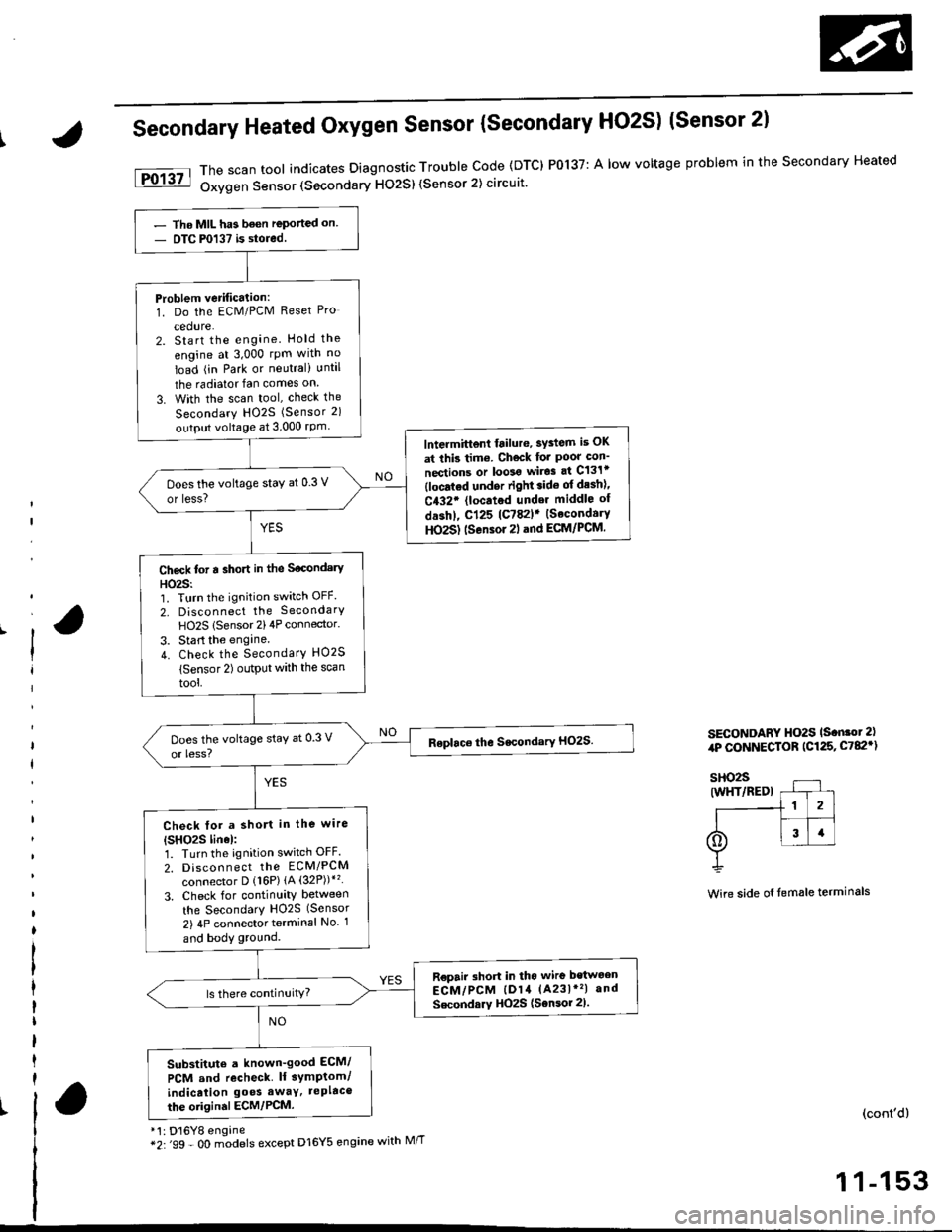
Secondary Heated Oxygen Sensor {secondary HO2S) (Sensor 2l
*'t : D16Y8 engine*2:'99 - O0 m;dels except D16Y5 engine with M//T
The scan tool indicates Diagnostic Trouble Code (DTC) P0137: A low voltage problem in the Secondary Heated
Oxygen Sensor (Secondary HO2S) (Sensor 2) circuit'
SECONDARY HO2S ls.n.ot 2),rP CONNECTOR (C125, C782')
Wire side oI temale terminals
(cont'd)
1 1-153
- Tho MIL has been reported on- DTC P0137 is stored.
Problem verification:1. Do the ECM/PCM Reset Pro
cedure.2. Start the engine. Hold the
engine at 3,000 rpm wlth no
load (in Park or neutral) until
the radiator fan comes on
3. With the scan tool, check the
Secondary HO2S (Sensor 2)
output voltage at 3,000 rPm
lntermittent frilure, sYdem is OK
at this tim6. Check for Poor con'
nections or loolo wir.3 at C131t(locatod undor right.ido of desh)'
C432. {located under middle of
dashl, cl25 lc782lr {SecondaryHO2S) tsensor 2l .nd ECM/PCM.
Does the voltage staY at 0.3 V
or less?
Ch6ck tot a sho.t in the S€condery
HO23:'1. Turn the ignition switch OFF.
2, Disconnect the SecondarY
HO2S lSensor 2)4P connector.
3. Start the engine.
4. Check the SecondarY HO2S
lsensor 2) output with the scan
tool,
Check tor a short in the wire
{SHO2S linel:1. Turn the ignition switch OFF.
2. Discon n ect tho EcM/PCM
connector D {16P) {A (32P))*'�
3. Check for continuity between
the SecondarY H02S (Sensor
2) 4P connector terminal No 1
and body ground.
R€pair short in tho wire bstwoen
ECM/PCM lD14 (A231*'�| and
Secondarv HOzS (Sensor 2).
Substitute a known-good ECM/
PCM and recheck lf 3ymptom/
indicalion go€s awaY, tePltco
the oiigin.l ECM/PCM.
Page 424 of 2189
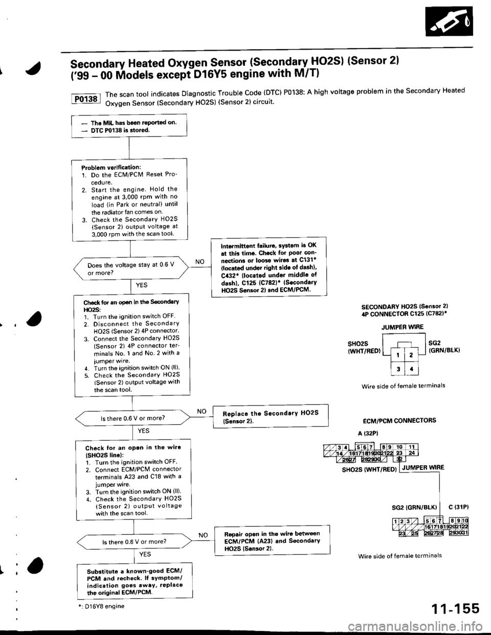
Secondary Heated Oxygen Sensor (SecondarytlO2S) (Sensor 2l
('99 - 00 lilodels except DtGYS engine with M/T)
The scan tool indicates Diagnostic Trouble code (DTC) P0138: A high voltage problem in the secondary Heated
Oxygen Sensor (Secondary H02S) (Sensor 2) circuit.
SECONDARY HO2S {S€nsot 2}
4P CONNECTOR Cl25 lc782l'
JUMPER WIRE
Ir
sH02s(WHT/RED)sG2{GRN/BLKI
Wire side of female termanals
ECM/PCM CONNECTORS
A (32P1
Wire side ot female termlnals
gs92g 111yp17p5py | .lutuPea wtne
- The MIL has beon reportod on.- DTC m138 is.tored.
Ploblem vorification:1. Do the ECM/PCN4 Reset Pro-
cedure.2. Start the engine Hold the
engine at 3,000 rpm with no
load (in Park or neutral) until
the radiator{an comes on
3. Check the SecondarY H02S(Sensor 2) output voltage at
3,000 rpm with the scan tool
lntormittont failuio, sYstom b OK
st thir timo. Check for Poor con_
nections ot loo39 wiJo3 af Cl3lr(located under right ride ot desh),
C432' (locatod undot middle of
dashl, Cl25 {C782lr (Secondaiy
HO2S Son3or 2l and ECM/PCM.
Does the voltage stay at 0 6 V
or more?
Ct€d( tor an opan in the Secondary
l|o2s:1. Turn the ignition switch OFF
2. Disconnect the SecondarY
HO2S (Sensor 2) 4P connector.
3. Connect the Secondary HO2S(Sensor 2) 4P conneclor ter_
minals No. 1 and No.2 with a
iumper wire.4. Turn the ignition switch ON (ll)
5. Check the SecondarY HO2S
lSensor 2) outptlt voltage with
the scan tool,
lsthere 0.6 V or more?
Check lor an open in the wiro(SHO2S line):1. Turn the ignition switch OFF.
2. Connect ECM/PCM connector
terminals A23 and C18 with ajumper wrre,
3. Turn the ignition switch ON (ll).
4. Check the SecondarY HO2S
{Sensor 2) outPut vo ltage
with the scan tool.
Repair opon in tho wire betwecn
ECM/PCM (A23) and SocondarY
HO2S {Sansor 2).ls there 0.6 V or more?
Substitut€ a known'good ECM/
PCM and recheck. It symptom/indication goes awey, JePlaco
the otiginel ECM/PCM
*i 016Y8 engine1 1-155
Page 425 of 2189
![HONDA CIVIC 1999 6.G Workshop Manual PGM-FI System
Secondary Heated Oxygen Sensor (Secondary HO2S) {sensor 2l
[FO13a]l The scan tool indic€tes Diagnostic Trouble Code {DTC) P0139: A slow response probtem in the Secondary Heated- Uxygen HONDA CIVIC 1999 6.G Workshop Manual PGM-FI System
Secondary Heated Oxygen Sensor (Secondary HO2S) {sensor 2l
[FO13a]l The scan tool indic€tes Diagnostic Trouble Code {DTC) P0139: A slow response probtem in the Secondary Heated- Uxygen](/manual-img/13/6068/w960_6068-424.png)
PGM-FI System
Secondary Heated Oxygen Sensor (Secondary HO2S) {sensor 2l
[FO13a]l The scan tool indic€tes Diagnostic Trouble Code {DTC) P0139: A slow response probtem in the Secondary Heated- Uxygen Sensor (HOzS) (Sensor 2) circuit.
1 1-156
- The MIL has been reported on.- DTC P0139 is stored.
Problem verification:1. Do the ECM/PCM Reset Pro-
2. Start the engine. Hold theengine at 3,000 rpm with noload {in Park or neutral) untilthe radiator fan comes on.3. With the scan tool, check theSecondary HO2S (Sensor 2)output at 3,000 rpm.
Intermiftent failure, system i! OKat this tims. Check for pool con-nections or loos6 wiles at C131.{located undor ght lide of dash),C432' (locrted under middle otd.shl Cl25 (C782lr (SocondaryHO2S) (Sonsor 2) and ECM/FCM.
Does the voltage stay within0.3 - 0.6 V for two minutes?
*: D16Y8 engine
Page 428 of 2189
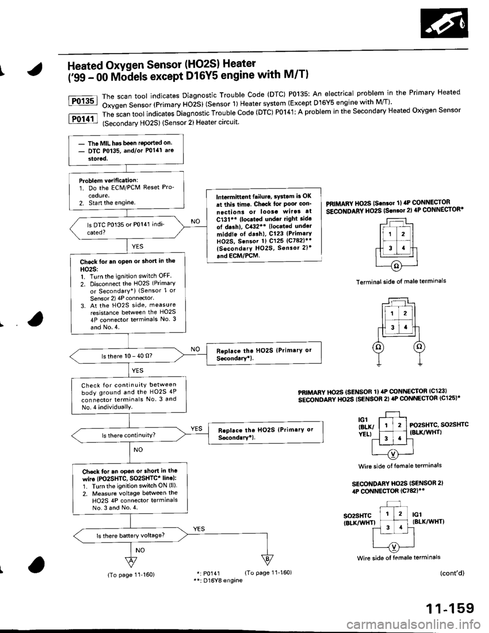
IHeated Oxygen Sensor (HO2S) Heater
i'ss - oo Mb-dels except D16Y5 engine with M/Tl
The scan toot indicates Diagnostic Trouble Code (DTC) P0135: An electrical problem in the Primary Heated
Oxygen Sensor (Primary ttOiS) (Sensor 1) Heater system {Except D15Y5 engine with M/T)'
The
-scan tool indicates Diagnostic Trouble Code (DTC) P0141; A problem in the Secondary Heated Oigen Sensor
(Secondarv HO2S) {Sensor 2) Heater circuit
Fo13sl
Fol11l
lntermiftent failuro, sYstom b OK
at thit limo. Ch6ck lor Poor oon'
nectiont or looso wita! at
C131'* {loc.tod und.t right ido
ol drshl, C432'* (located undel
middlo of dashl, C123 (PrimarY
HOzS, Sensor 1) C125 (Ct82lr'
(socondary HO2S, Sensor 2)t
.nd ECM/PCM.
PRIMAFY HO2S ls.n.or ll rrP CONNECTOR
SECOITIDARY HO2S (Srn.ol21 4P CONNECTOR'
Terminal side of male terminals
PRIMARY HO2S {SENSOR 1} ilP @NI{ECTOR lc123l
sEcoNDARY HO2S ISENSOR 2) aP @NNECTOR (C125)'
3l-, l-tl-t Fo2sHrc. so2sHrc
ver.t l ^-1 .'l {BLK/wHrl
11 '!'l-l
| --=- Iu----{v)'---..-'
Wire side of {emale terminals
SECO'TIDARY Ho2S (SENSOR 2,
4P CONNESTOR {C7&llt'
so2sHTc(BLKnflHTlIBLK/WHT)
(cont'd)
1 1-159
Wire side oI female terminals
r: p0141 {To page 11-160}**: D16Yg engine
- The MIL has been reponed on.- DTC P0135. and/or P0141 are
storod.
Problem vorification:1. Do the ECM/PCM Reset Pro-
cedute.2. Stan the englne.
Chock foi an open or short in the
HO25:1. Turn the ignition switch OFF
2. Disconnect the HO2S (Primary
or Secondary*) lSensor 1 or
Sensor 2) 4P connector'
3. At the H02S side, measure
resistance between the HO2S
4P connector terminals No. 3
and No.4.
ls there 10 - 40 n?
Check for continuity between
body ground and the HO2S 4P
connector terminals No. 3 and
No.4 individuallY.
Check for an opon or short in lho
wire (PO2SHTC, SO2SHTC+ line):'1. Turn the ignition switch ON (ll).
2. Measure voltage between the
H02S 4P connector termlnalsNo.3 and No.4.
{To page 11-160}
Page 1502 of 2189
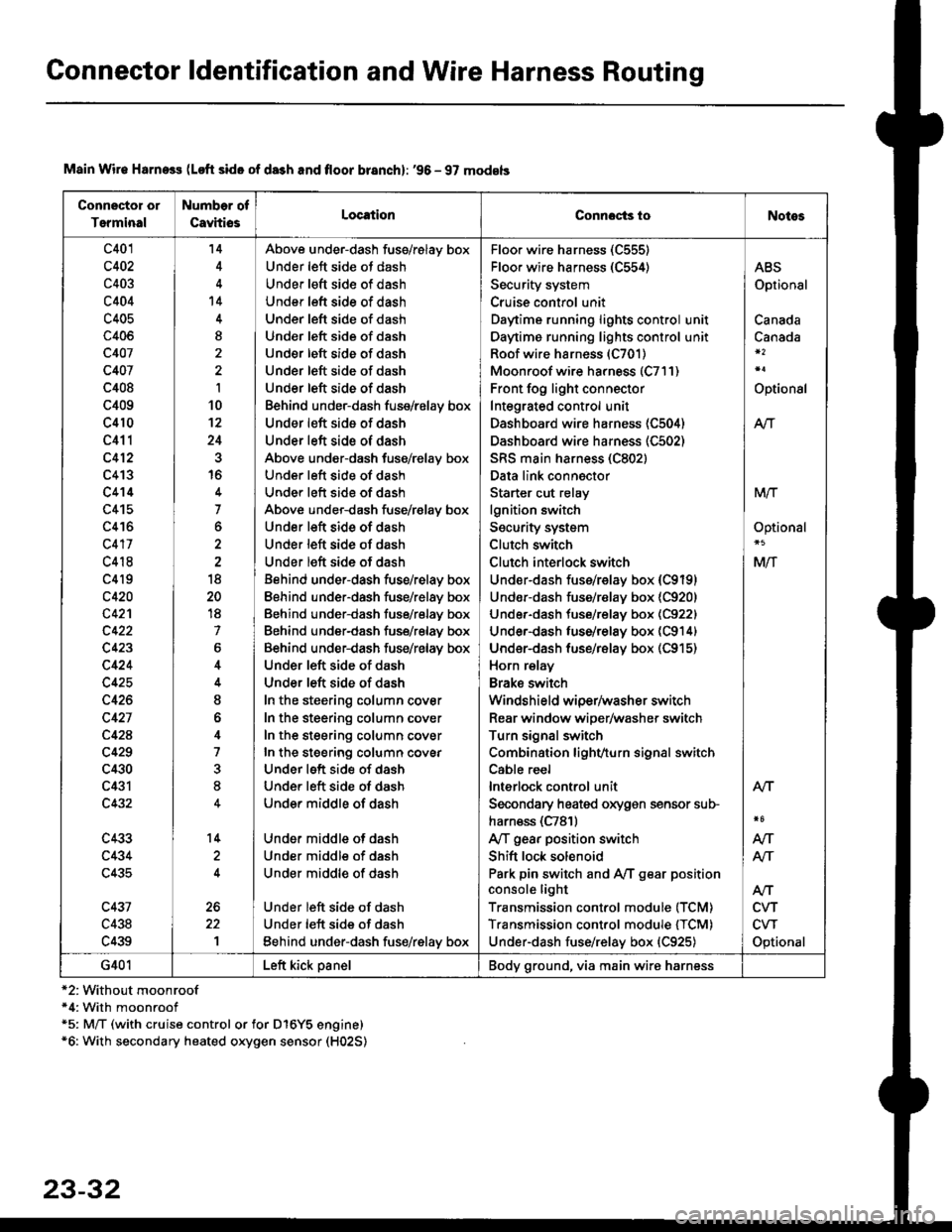
Connector ldentification and Wire Harness Routing
Connector or
Terminal
Number of
CavhiosLocationConnocts ioNotes
c401
c402
c403
c404
c405
c406
c407
c407
c408
c409
c410
c411
c412
c413
c414
c415
c416
c417
c418
c4l9
c420
c42'l
c423
c424
c425
c426
c427
c42A
c429
c430
c431
c432
c433
c434
c435
c431
c438
c439
'14
't4
I
I
10't2
24
16
7
o
18
20
18
7
6
I
o
4
7
8
14
1
Above under-dash fuss/relay box
Under left side ot dash
Under left sid€ of dash
Under left side of dash
Under left side of dash
Und€r left side of dash
Under left side of dash
Under left side of dash
Under left side of dash
Behind under-dash fuse/relay box
Under left side of dash
Under left side of dash
Above under-dash fuse/relay box
Under left side of dash
Under left side of dash
Above under-dash fuse/r€lay box
Under left side of dash
Under left side of dash
Under left side of dash
Behind under-dash fuse/relay box
Eehind under-dash fuse/relay box
Behind under-dash fuse/relay box
Behind under-dash fuse/relay box
Behind under-dash fuse/relay box
Under left side of dash
Under left side of dash
In the steering column cover
In the steering column cover
In the steering column cover
In the steering column covEr
Under left side of dash
Under left side of dash
Under middle of dash
Under middle of dash
Under middle of dash
Under middle of dash
Under left side of dash
Under left side of dash
Eehind under-dash fus€/relay box
Floo. wire harness (C555)
Floor wire harness (C554)
Security system
Cruise control unit
Daytime running lights control unit
Daytime running lights control unit
Roof wire harness (C701)
Moonroof wire harness (C7l1)
Front fog light connector
Integrated control unit
Dashboard wire harness (C504)
Dashboard wire harness (C502)
SRS main harness (C802)
Data link connector
Starter cut relay
lgnition switch
Security system
Clutch switch
Clutch interlock switch
Under-dash fuss/relay box (C9191
Undor-dash fuse/r€lay box {C920)
Under-dash tuse/relay box (C922)
Under-dash luse/relay box (C914)
Under-dash fuse/rBlay box (C915)
Horn relay
Brake swilch
Windshield wiper/washer switch
Rear window wiper/washer switch
Turn signal switch
Combination lighvturn signal switch
Cable reel
lnterlock control unit
Secondary heated oxygen sensor sub-
harn€ss (C781)
Ay'T gear position switch
Shift lock solenoid
Park pin switch and Ay'T gear position
console light
Transmission control module (TCM)
Transmission control module {TCM)
Under-dash fuse/relay box {C925)
ABS
Optional
Canada
Canada
Optional
Atr
MTT
Optional
Mlf
NT
Atf
CVT
CVT
Optional
AN
Atr
G401Left kick panelBody ground, via main wire harness
Main Wir€ Harness (Loft side of da3h and floor branch): '96 - 97 models
*2:Without moonroof*4: With moonroof*5: M/T (with cruise control or for D16Y5 engine)*6: With secondary heated oxygen sensor (H02S)
23-32
Page 1504 of 2189
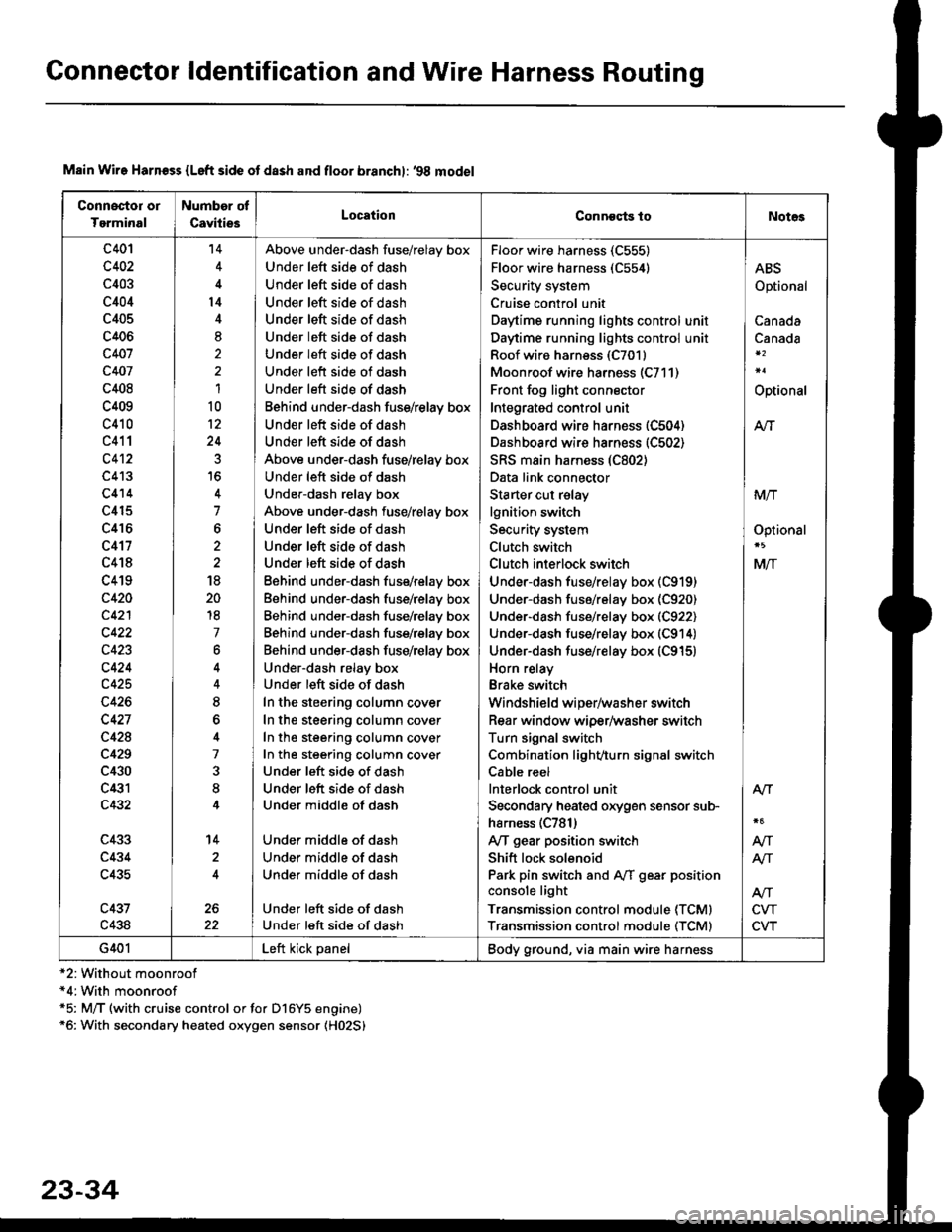
Connector ldentification and Wire Harness Routing
Connoctor or
Tgrminal
Number of
CavitiesLocationConneqts toNot€s
c401
c402
c403
c404
c405
c406
c407
c407
c408
c409
c410
c411
c4't2
c413
c414
c415
c416
c417
c418
c419
c420
c421
c422
c423
c424
c425
c426
c427
c428
c429
c430
c431
c432
c433
c434
c435
c437
c438
't4
l4
8,
1
10
12
24
7
6
18
20
18
7
6
8
7
8
14
2
Above under-dash fuse/relay box
Under left side of dash
Under left side of dash
Under left side of dash
Under left side of dash
Under left side of dash
Under left side of dash
Under left side of dash
Under left side of dash
Behind under-dash fuss/relay box
Under left side of dash
Under left side of dash
Above under-dash fuse/relay box
Under left side of dash
Under-dash relay box
Above under-dash fuse/relay box
Under left side of dash
Under left side of dash
Under left side of dash
Eehind under-dash fuse/relay box
Behind under-dash fuse/relay box
Behind under-dash fuse/relay box
Behind under-dash fuse/rslay box
Behind under-dash fuse/relay box
Under-dash relay box
Under left side of dash
In the steering column cover
In the steering column cover
In the steering column cover
In the steering column cover
Under left side of dash
Under left side of dash
Under middle of dash
Under middle of dash
Under middle of dash
Under middle of dash
Under left side of dash
Under left side of dash
Floor wire harness (C555)
Floor wire harness (C554)
Security system
Cruise control unit
Daytime running lights control unit
Daytime running lights control unit
Roof wiro harness (C7011
Moonroof wire harness (C711)
Front fog light connector
Integrated control unit
Dashboard wire harness (C504)
Dashboard wire harness (C502)
SRS main harness (C802)
Data link connector
Starter cut relay
lgnition switch
Security system
Clutch switch
Clutch inlerlock switch
Under-dash fuse/relay box (C919)
Under-dash fuse/relay box (C920)
Under-dash fuse/relay box (C922)
Under-dash fuse/relay box (C914)
Under-dash fuse/relay box (C915)
Horn relay
Brake switch
Windshield wiper/washer switch
Rear window wiper/washer switch
Turn signal switch
Combination light/,turn signal switch
Cable reel
lnterlock control unit
Secondary heated orygen sensor sub-
harness (C781)
Ay'T gear position switch
Shift lock solenoid
Park pin switch and Aff gear position
console light
Transmission control module (TCMI
Transmission control module (TCM)
ABS
Optional
Canada
Canada
Optional
M
MIT
Optionsl
MlT
Alr
NT
NT
CVT
CVT
G401Left kick panelBody ground, via main wire harness
Main Wire Harn€ss {Left side ot dash and floor branchl: '98 model
*2: Without moonroof*4:With moonroof*5: M/T (with cruise control or for D16Y5 engine)*6: With secondary heated oxygen sensor (H02S)
23-34
Page 1506 of 2189
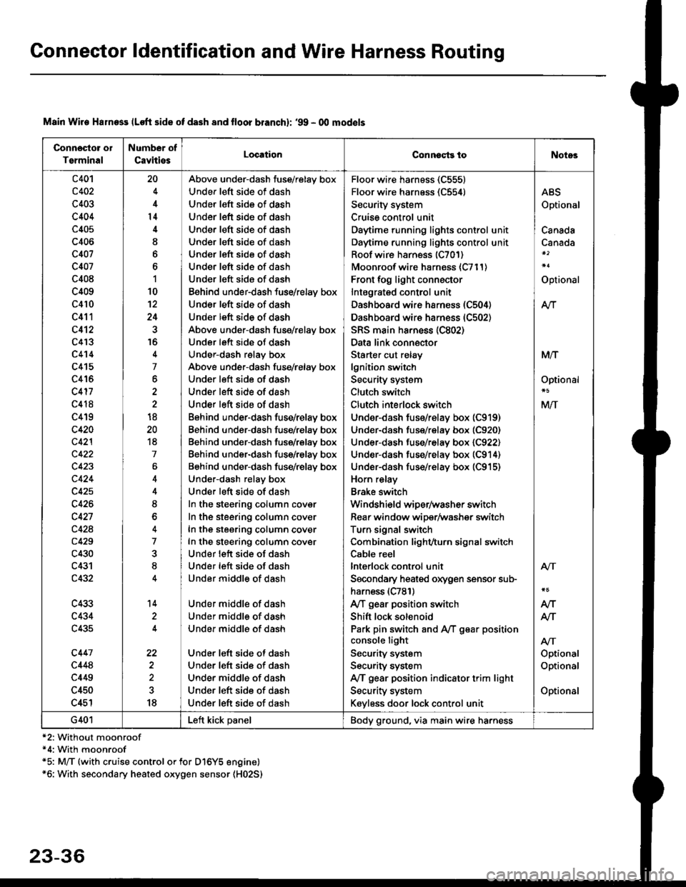
Connector ldentification and Wire Harness Routing
Connosto! ol
Tsrminal
Number of
CavitiesLocationConnoqtg toNotes
c401
c402
c403
c404
c405
c406
c407
c407
c408
c409
c410
c411
c412
c4'�I3
c4't4
c415
c416
c417
c418
c419
c420
c42l
c422
c423
c424
c425
c426
c427
c428
c429
c430
c431
c432
c433
c434
c435
c447
c448
c449
c450
c451
20
4
14
I
6
1
10
12
24
16
4
7
6
2
18
20
18
7
4
8
o
7
8
14
22
18
Above under-dash fuse/relay box
Under left side of dash
Under left side of dash
Under left side of dash
Under left side of dash
Under left side of dash
Under left side of dash
Under left side of dash
Under left side of dash
Behind under-dash fuse/relay box
Under left side of dash
Under left side of dash
Above under-dash fuse/relay box
Under left side of dash
Under-dash relay box
Above under-dash fuse/relay box
Under left side of dash
Under left side of dash
Under left side of dash
Behind under-dash fuse/relay box
Behind under-dash fuse/relay box
Behind under-dash fuse/relay box
Behind under-dash fuse/relay box
Behind under-dash fuse/relay box
Under-dash relay box
Under left side of dash
In the steering column cover
In the steering column cover
In the steering column cover
In the steering column cover
Under lett side of dash
Under left side of dash
Under middle of dash
Under middle of dash
Under middle of dash
Under middle of dash
Under left side of dash
Under left side of dash
Under middle of dash
Under left side of dash
Under left side of dash
Floor wire harness (C555)
Floor wire harness (C554)
Security system
Cruise control unit
Daytime running lights control unit
Daytime running lights control unit
Roof wire harness (C701)
Moonroof wire harness {C711)
Front fog light connector
Intagrated control unit
Dashboard wire harness (C504)
Dashboard wire harness (C502)
SRS main ha.ness (C802)
Data link connector
Starter cut relay
lgnition switch
Security system
Clutch switch
Clutch interlock switch
Under-dash fus€/relay box (C919)
Under-dash fuse/relay box (C920)
Under-dash fuse/relay box (C922)
Under-dash fuse/relay box (C914)
Under-dash fuse/relay box (C915)
Horn relay
Brake switch
Windshield wiper/washer switch
Rear window wiper/Washer switch
Turn signal switch
Combination light/turn signal switch
Cable reel
lnterlock control unit
Secondary heaied oxygen sensor sub-
harness (C781)
A/T gear position switch
Shift lock solenoid
Park pin switch and A,/T g€ar position
console light
Security system
Security system
IVT gear position indicator trim light
Security system
Keyless door lock control unit
ABS
Optional
Canada
Canada
Optional
At-|.
M/T
Optional
M/T
Atr
Optional
Optional
Optional
Atr
AIT
AJ-|.
G401Left kick panelBody ground, via main wire harness
Main Wire Halness lLoft side of dash 8nd lloor branchl: '99 - 00 mod€ls
*2: Without moonroof*4: With moonroof*5: M/T (with cruise control or for Dl6Y5 engine)*6: With secondary heated oxygen sensor (H02S)
23-36