Page 1861 of 2189
Ground Distributiofl (cont'd)
- G201 andG202
NOTE: Wires shown wrthout color codes are black.
RIGHTHEAD.LIGHTPage110-12
tl
tl
110-9
{}tl
tl
LEFT FRONTPARKING/TURNSIGNALLIGHTPages 110-2,1 10-7, and110-9
()
WIND.SHIELDWASHERMOTORPage 91PHOTA 3
ll
tl
REARwtNDowWASHERMOTORPage 92
tl
tt
c205
RIGHT FRONTPARKING/TURNStcNAL RADIATORLIGHT FANPaoes 110-2, MOTOR11d-7, and Page 63
'99-'�00
.- Canada -l
i wnsxen i cnurse, FLUID ; CONTROL' LEVEL . ACTUATOR' SWITCH I paoe 34-2; Page 80-3 i eu6ro re'f-1 ' f-1
2Y2
c211
14-4
I'G201'Lv G2o2
Page 1983 of 2189

A/T Gear Position Indicator (conrd)
- How the Circuit Works
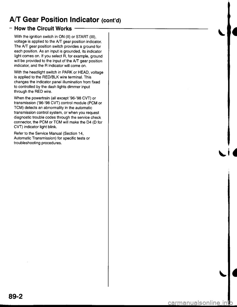
With the ignition switch in ON (ll) or START (lll),
voltage is applied to the A,/T gear position indicator.
The A,/T gear position switch provides a ground for
each position. As an input is grounded, its indicator
light comes on. lf you select R, for example, ground
will be provided to the input of the A,/T gear position
indicato( and the R indicator will come on.
With the headlight switch in PARK or HEAD, voltage
is applied to the RED/BLK wire terminal. This
changes the indicator panel illumination from fixed
to controlled by the dash lights dimmer input
through the RED wire.
When the powertrain (all except '96-'98 CVT) or
transmission ('96198 CVT) control module (PCM or
TCM) detects an abnormality in the automatic
transmission control system, or when you request
diagnostic trouble codes through the service check
connector, the PCM or TCM will make the D4 (D for
CVT) indicator light blink.
Refer to the Service Manual (Section 14,
Automatic Transmission) for specific tests or
troubleshooting procedures.
\ia
89-2
Page 1988 of 2189
Headlight Switch
(
UNOER-OASHFUSEiRELAY BOXPHOTO 58
Sse PowerDisiribution,page 10-12-
UNDER-HOODFUSE/RELAYBOX
H
FUSE 22L H/ILOIY SEAflt0a
COMBINATIONLIGHTswtTcHHead-lightSwltch
L-----J'SeePower' Distribution,
: Page 10-12.
a
{
UNDER-DASHFUSE/RELAYBOXFUSS 2tF H/LLOW EgAtl
FUSE 4R TIILHIG|{ AEAMt0A
vtEw 53
_ ___:==
1-sr*r"
_
l_-.__
_,_.
it:
".0-", i ".o ".u I i ".o u.,
iti
Iti
llr
lli
lli
--'l --u{.sao,l,. i 2
neourrr I nroerul'/Ftr'o :---,
,.|,___ui
il--Tll''%i'sr"' ii
it@4li**"""li-; s-i5-r i .
I
I
i-t-;;l
1 J lff*n"' IL-.J----J
nrrl'?;Ii
ffif'illi! i
*itn12
HI
- - ) ot[*o1- -] ot. "roo a]ot.HEAD PAnK I panx IPAnK
!a
- -I DAYTIME
IRUNNINGI LIGHTS
! RESTSTOR'- Paqe 110-13
100
Page 1990 of 2189
100-2
Headlight Switch (cont'd)
-.I UNDER.DASHRom UderdashFur€/Bslay 8ox orprevrous prge.
- - -ri-Y c421 13 Y C5s1'- ll PHoro 63 ll esoro6J
neoialx I u/EW 50 BEDelfi i v'Edu7
'f ---- Hatchback l, Coupe and Sedan
c2o1 : I !'--'l Itlt5i:^- :i"'oYizt i i Iri"Je'tl
i l3pfif.l-"o."-i ".o,".*l =,a,e.Fema,e, ll L--J pe6161ja , ll terminals reversed
: tr_ _ _ _ _ _ _ _ _ _Y::_ _ _ _ _:
c202PNO|O 23ytEw 1
LEFTBRAKELIGHT/TAILLIGHTPage 110-5
9('99100 models 18)
FED/BLK
RIGHTTAILLIGHTPage 110-5
c562 .
vtEw42
c605
wEw a
RIGHTBRAKELIGHT/TAILLIGHTPage 110-5
LEFTLICENSEPLATELIGHTPage ! 10-5
for '99-'00 models
FUSE/RELAYBOX
1(cruise 3)c604 5
FEO/BLK
"ao,"a* |
I
/---lI \---t
LEFTTAILLIGHTPage 110-5
\;,,
LEFT FRONTPARKING/TURNSIGNALLIGHTPage 110-2
RIGHTLICENSEPLATELIGHTPage 110-5
,rUrOO ro.",. ?, I
r-\\_,
".,"-[TI
RIGHT FRONTPARKING/TURN SIGNALLIGHTPage 1l0-2
Page 2002 of 2189
Fog Lights
_ Vehicles pre'wiredfor accessorysecurity system
SECURITY SYSTEMCONNECTOR(oPT|ON)
"!'19*13*
u,.*,"
a
c403
----.t COMB|NAT|ON
: swrrcHI PHOIOT2
lvtEw u
I
I
FOG LIGHTIN-LINE FUSE
FUSFI H,'lt.cw 8llaa
BLKI .--<
t_G2O2
gee GroundDistribution,pag€ 144.
i t-' BsJ:?'tr! li[?i,i'*'LJ------J
_ _tlI',-Yfi::"* *,*,,
a,
ot'
tttr(
---g-----J _- -"il( - see H€dbnt
;eo'q;r. I-) oaoe loo.
See Headlights '(Canada)
l-l 1 aeomnr
k-j'/,-dl15 llJ - - oplronal Fog Light swttch Harness - - -.I UNOER.DASH
I FUSE/RELAY
FUSE2l I BOx
R H/r- i PHoro 5errow BEA
I
---!':--J--1frf':l,"
i::.,.n.*BEo,naHT I !7
*':#i,!J
^ L--8-
i33o,,nno t f-
"-'-:E+
1 10-10
Page 2004 of 2189
Headlights
- Coupe and Sedan
Vehicles pre-wired- - - for accessorysecurity system
5 f| C419 PHQ|O63 vtEW4s
UNDER-HOOD| / FUSE 48 | FUSE/RELAY: HEADLTGHT :BOXI I 3oa I pHoroT
LJ----JI Y C3s2wHrl PYo-rg8- ulEY:?- - - - - - canadaWHT
Head-ligtrtSwlich
COMBINATIONLIGHTswrTcH
".;L
L--{..---1 Y Cs01
".o,o"n I i[?,lo,uo ^..?fiurti
ce.l, *i;[fl?ive /a V|EW z1
i--r------''i
/A xrcx geru
;".1p$31"f'""InoFY;�]j:::-:
T_l Eqr I--g------J
RIGHTHEADLIGHT
lL
r-: G401PHOTO 57
See GroundDistdbution,page 14-4.
Soe GroundDistribution,page 14-4.
SECURIry SYSTEMCONNECTOR(oPTloN)i t-'d*ltr! lF"{il'.]'*'
nero't t-+- *.oo*jpinx I pl66 HEAo J cmx
- Canada -
---J4- ----J See HeadliohtB1 Y Swirch,-.^^-- I# oao6 100.
FUSE 21F i/tIOW AEAM
FUSE 4B H/LHIGll BEAM
UNDER.DASHFUSE/RELAYBOX
1IIGH
110-12
Page 2006 of 2189

Headlights (cont'd)
- How the Circuit Works
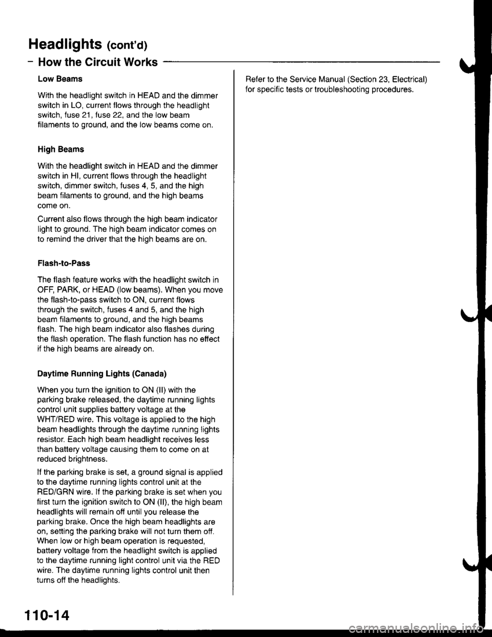
Low Beams
With the headlight switch in HEAD and the dimmer
switch in LO, current tlows through the headlight
switch. fuse 21 . fuse 22. and the low beam
tilaments to ground, and the low beams come on.
High Beams
With the headlight switch in HEAD and the dimmer
switch in Hl, current flows through the headlight
switch, dimmer switch, fuses 4, 5, and the high
beam filaments to ground, and the high beams
come on.
Current also llows through the high beam indicator
light to ground. The high beam indicator comes on
to remind the driver that the high beams are on.
Flash-to-Pass
The flash feature works with the headlight switch in
OFF, PARK, or HEAD (low beams). When you move
the flash-to-pass switch to ON, current flows
through the switch, fuses 4 and 5, and the high
beam filaments to ground, and the high beams
flash. The high beam indicator also flashes during
the flash operation. The flash function has no effect
if the high beams are already on
Daytime Running Lights (Canada)
When you turn the ignition to ON (ll) with the
parking brake released, the daytime running lights
control unit supplies battery voltage at the
WHT/RED wire. This voltage is applied to the high
beam headlights through the daytime running lights
resistor. Each high beam headlight receives less
than battery voltage causing them to come on at
reduced brightness.
lf the parking brake is set, a ground signal is applied
to the daytime running lights control unit at the
RED/GRN wire. lf the parking brake is set when you
first turn the ignition switch to ON (ll), the high beam
headlights will remain off until you release the
parking brake. Once the high beam headlights are
on, setting the parking brake will not turn them ofi.
When low or high beam operation is requested,
battery voltage from the headlight switch is applied
to the daytime running light control unit via the RED
wire. The daytime running lights control unit then
turns off the headlights.
Refer to the Service Manual (Section 23, Electrical)
for specific tests or lroubleshootrng procedures.
110-14
Page 2010 of 2189

Dash and Console Lights
!'-I- ---1UNDER-HooD
| / FUSE '18 | FUSETRELAY| ) xeroucrr lBox
I t.* | Pl1o to .
L-L---J9 Y C3s2wHr I etoroa See power
arr- Distribution.
wnr I - PagelGl2
86 l,COMBINATIONI r---F--'t Head qhr I LtcHT
| | lswrtch- l"syllgl| | HEADa )OFF r .:::::.'| | "'oo)-o" ; 1,;;7-a"'
I L---95-.t IL----g--------JB1 Y , sEcuRtw SYSTEM".oo"l [_ _______---j coNNEcroR (opT|oN)
;f nED/ca 3 \f [email protected]*----FED/GRN II C4227 A PHofose vlEw 16-^---:-- --.l UNDER-DASH
I f;.*--,Tl 333J'"#1nn''"n"n iFiifiiiLA.vINSTAUXENTuGHTs ' PHoro 58t* . , 1
Vehicles pre-wiredfor accessorysecunry.sysrem
",o ".* ! i[o',,Bu' ".o ".* ! !;91o,u, poj;T;o6} coNNEcroR
O
"ro ".* !
"." Jlfr ;1+.,:.,,
"'o "'*
|
"'o ".."
|
"'o "'.*
|
"'"'"''*
| F$S^ff".t-;t;'t
['jl' ,, | "'-'x----lgr- -:'-l:t:!y!-
*,,,""::,:";illttS,iii',""0","'=ss.oomode'�s I if----tg;-;'"t1*-:.1ll r I I Poshior !! Indicrtor !it HErren t neAren I l.*. 94!r$f.._ ltndtcErol ll circu! . .l!
I ;ffiF' I ;ffiF' n=uu, ! i9d#"iufftl*;1#ff"'"I :l:-i!"' oo f ';dio-'" PU'H ll
r-z-----',-.--j";."..J:lqtT I il ! !i8noHt"
iI _:: i
-7-----1 r-4(.-1 neo l----1
,.-1.-E !!A ilfr. !
JL-r--J
.i:i9:'::i Bnl,r'i @ ^.i i @,o,1
"'"*
| @^.,l
-____ffi-:s;J
,LjrY##Y_i
$ffi_l
-l
i"l
i
ilffl
1l-
I l\Y','! ! \7(i , A "o.u "t'A3Y ' E1l"f I
114