Page 1441 of 2189
A/C System
CONDENSER FAN RELAY 4P SOCKET
A/C system does not come on
{comDressor and fan).
Check the No. 56 fuse in theunder'hood fuse/relay box andthe No. 17 fuse in the under-dashfuse/relay box.
ReDlace the fus6{s}, and recheck.
Check for tn open in the wire:
1. Remove the condenser lanrelay from the u nderhood
luse/relay box.2. Turn the ignition switch ON {lli.3- Measure the voltage betweenthe No. 4 terminal of the condenser fan relav 4P socketand body ground.
Repair open in the wire between
the No. 17 fuse and the con-denser fan r6lay,
Check the under-hood fus€/r6laybox:Measure the voltage between the
No. 2 terminal of the condenser
fan relay 4P socket and bodyground,
YES
Io page 22-18
(cont'd)
Page 1471 of 2189

l'f .
Electrical
Special Toofs .,....................,23-2
Troubleshooting
Tips and Precautions ..............,.................... . 23-3
Five-step Troubleshooting .............. ......... . . 23-5
wire color codes ..........,23-5
Schematic Symbols ........,................... . . .. .... 23-6
Relay and Control Unit Locations
Engine Compartment ...,..................... ... .. . 23'7
Dashboard ......................23-8
Dashboard/Door ......... 23-12*Airbags ................. ....... Section 24
Air Conditioning ......... Section 21
Aftelnator ..........."""" """ 23-112
Anti-lock Brake System {ABS) Section 19*A/T Gear Position Indicator .....................,. .... ... 23-149
Automatic Transmission Svstem .... . ....... Section 14
Batterv ......... . . . ... ...... .......23-91
Blower controls .. . ... Section 2l
Charging System ....'...........23'112
Connector ldentilication and Wire Harness
Routing .................. ......23'13
Cruise Control ............,........23-240
Dash Lights Brightness Controller ............. ....... 23-180
Fan controfs "" 23'126
Fuel PumD ........ . ........ section 11
Fuses/Refay ...............,..,,.. 23'62
PGM-FI Control System ......................,....... Section 1 1
*Gauges
Circuit Diagram ....,.,.......23-131
Fuef Gauge ...........'.'.......23-142
Gauge/lndicator .. . .. 23-129
Ground Distribution .. . 23-75
Heatei controls .. . ..... Section 21*Horn................. ...............23-196
*tgnition Switch ....................23-89
lgnition System .......,.... 23-102
*lntegrated Control Unit ....................................... 23-156
fnterlock System ,........ . . , ,23-144
Lighting System . . . .. ......... 23-161
Lights, Exterior
Back-up Lights ..'............23'171
Brake Lights .................. 23'174
Daytime Bunning Lights (Canadal ............... 23'166
Front Parking Lights ......,................ .'. .......... 23-167
Front Turn Signal Lights .......... . . ............ ..,.23-167
Headtights ....".'....-... ..... 23'167
High Mount Brake Light ...................... ... .23'179
License Plate Lights ...... 23'176
Taitfights ................ .......23'171
lnterior Lights ..-.......,, . 23-142
Moonroof ..,.................,........ 23-235
Power Distribution ....... . . .23-61
Power Door Locks .......,,,. .23'251
Power Mirrors ,..............,.,...23'206
Power Relays ....... . ...... . . .. 23-86
Power Windows ............,,....23-220
Rear Window Defogger .......................... . . ... . . 23-2OO
Spark Plugs . ..... . ........ .....23-111
Slarting System ................23-93*stereo Sound Svstem ,................. ..... ... . ... ,.,.,,23'147'Supplemental Restraint System (SRS) ... . Section 24
Turn Signal/Hazard Flasher System .......'.'....-... 23-173
*Undel-dash Fuse/Relay Box ............,.................. 23-85
vehicfe soeed sensor (VSSI """" ""' 23-140+Wipers/Washers .........,.,.,...23-214
NOTE: Unless otherwise specified, references to auto-
matic transmission (Mf) in this section include the CVT.
Page 1473 of 2189

Troubleshooting
ll.
Tips and Precautions
Bef ore Troubleshooting
. Check applicable fuses in the appropriate fuse/relay
box.
. Check the battery for damage, state of charge, and
clean and tight connections.
. Check the alternator belt tension.
CAUTION:
. Do not quick-charge a battery unless the battery
ground cable has been disconneqted, otherwise you
will damage the alternator diodes.
. Do not attempt to crank the engine with the battery
ground cable loosely connecled or you will severely
damage the wiling,
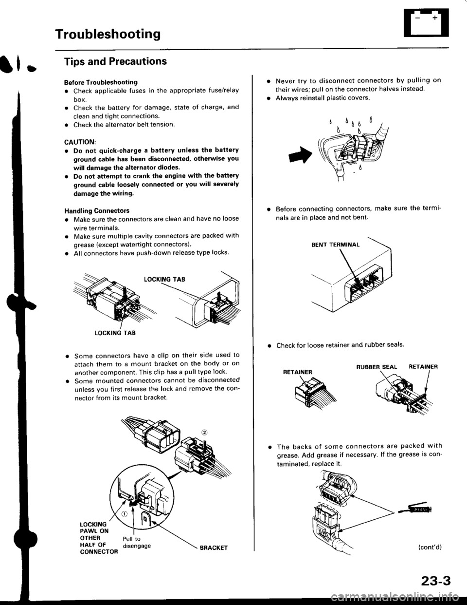
Handling Connectois
. Make sure the connectors are clean and have no loose
wire terminals.
. Make sure multiple cavity connectors are packed with
grease (except watertight connectors)
. All connectors have push-down release type locks.
Some connectors have a clip on their side used to
attach them to a mount bracket on the body or on
another component. This clip has a pulltype lock.
Some mounted connectors cannot be disconnected
unless you first release the lock and remove the con-
nector from its mount bracket.
LOCKINGPAWL ONOTHERHALF OFCONNECTOR
Pull todrsengage
LOCKING TAB
BRACKET
Never try to disconnect connectors by pulling on
their wires; pull on the connector halves instead
Alwavs reinstall plastic covers.
Before connectang connectors,
nals are in place and not bent.
make sure the terml-
. Check for loose retainer and rubber seals.
RETAINER
The backs of some connectors are packed with
grease. Add grease if necessary. lf the grease is con-
taminated, replace it.
(cont'd)
23-3
Page 1477 of 2189
Relay and Control Unit Locations
Engine Compartment
UNDER.HOOD ABS
FUSE/RELAY BOX
CONDENSER FAN
RELAY
UNDER.HOODFUSE/RELAY BOX
MOTORRELAY
A/C COMPRESSORCLUTCH RELAY
RADIATORFAN RELAY
ELD UNIT
t:
tr
tr
uI Il I tl I
23-7
Page 1479 of 2189
D
INTEGRATEDCONTROL UNITUNDER.OASHFUSE/RELAY BOX
HORN RELAYI Wire colors: WHT/GRttt, WXf/Cnru,l
[GRY, and BLU/RED ,J
POWER WINDOW RELAY
INTERLOCK CONTROL UNIT
'gtP"tat{}r) (}t /t t ------,)
F;;snHn-nnn"nf-H-n o
F !r rr rr rr r,r Lr Ll u u l,r
Fnnnnnnnrrrr-1F rr rr rJ LJ rJ r-r t-r L-r LJ Lr ||J
u_::;_:_:_:_:_l_;I::
*TCM (CVT)
*: Coupe
23-9
Page 1481 of 2189
O
UNDER.OASHFUSE/NELAY BOX
. TCM (CVT): Coupe. KEYLESS DOOR LOCK CONTROL UNIT: '99 model {USAI
REAR WINDOWDEFOGGEB
INTERLOCK CONTROL UNIT
POWER WINDOW RELAY
oF- -=----rr Jl r c
23-11
Page 1483 of 2189

Connector ldentification and Wire Harness Routing
D
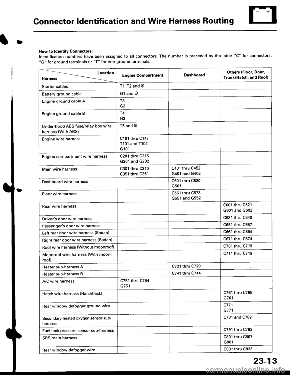
How to ldentify Connectors:
ldentification numbers have been assigned to all connectors. The number is preceded by the letter "C" for connectors,"G" for ground terminals or "T" for non-ground terminals.
Location
HarnessEngine CompartmentDashboardOthers {Floor, Door,
Trunk/Hatch, and Rootl
Starter cablesT1, T2 and @
Battery ground cableG1 and O
Engine ground cable AT3
G2
Engine ground cable BT4
Under-hood ABS fuse/relay box wire
harness (With ABS)
t5 ano (9
Engine wire harnessCl01 thru C147
T101 and T102
G101
Engine compartmenl ware harnessC201 thru C215
G201 and G202
Main wire harnessC301 thru C310
C351 thru C361
C401 thru C452
G401 and G402
Dashboard wire harnessC501 thru C520
G501
FIoor wire harnessC551 thru C573
G551 and G552
Rear wire harnessC601 thru C62l
G601 and G602
Driver's door wire harnessC631 thru C640
Passenger's door wire harnessC651 thru C657
Left rear door wire harness (Sedan)C661 thru C664
Right rear door wire harness (Sedan)C671 thru C674
Roof wire harness (Without moonroof)C701 thru C719
Moonroof wire harness {With moon-
roof)
C7l'l thru C719
Heater sub-harness AC721 thru C729
Heater sub-harness BC7 41 thtu C7 44
Ay'C wire harnessC751 thru C754
G751
Hatch wire harness (Hatchback)C761 thru C768
Rear window defogger grgund wirec771
G171
Secondary heated orygen sensor sub-
narness
C781 and C782
Fuel tank pressure sensor sub-harnessC791 thru C793
SRS main harnessC801 thru C807
G801
Rear window defogger wireC831 thru C833
Page 1484 of 2189

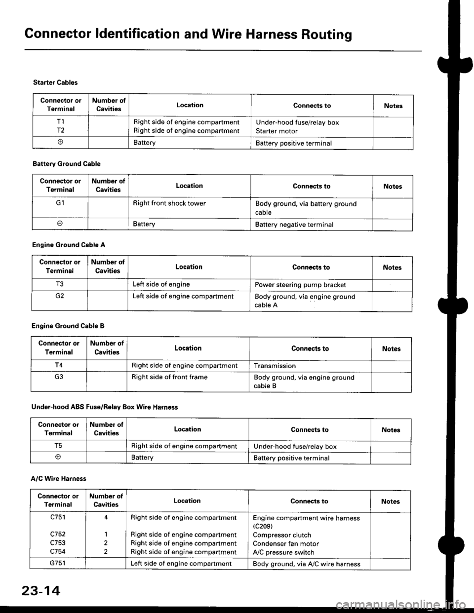
Connector ldentification and Wire Harness Routing
Connector or
Terminal
Number of
CavitiesLocalionConnec{s toNotes
T,I
r2
Right side of engine compartment
Right side of engine compartment
Under-hood fuse/relay box
Starter motor
BatteryBattery positive terminal
Starter Cables
A/C Wire Harness
Battery Ground Cable
Connector or
Terminal
Number of
CavitiesLocationConn€cts toNotos
Right front shock towerBody ground, via battery ground
caDte
oBafteryBattery negative terminal
Engine Ground Cable A
Conn€qtor or
Terminal
Number ot
CavitiosLocationConnects toNoles
T3Left side of enginePower steering pump bracket
G2Left side of engine compartmentBody ground, via engine ground
cable A
Engine Ground Cable B
Connector or
Terminal
Number of
CavitiesLocationConnecls toNoles
T4Right side of engine compartmentTransmission
Right side of front frameBody ground, via engine ground
cable B
Under-hood ABS Fusa/Relay Box Wire Harness
Connector or
Tgrminal
Number oI
CavitiesLocationConneqts toNotes
T5Right side of engine compartmentUnder-hood fuse/relay box
@BaneryBattery positive terminal
Connector or
Terminal
Number of
CavitiesLocationConnects toNotes
c753
c754
1
2
Right side of engine compartment
Right side of engine compartment
Right side of engine compartment
Right side of engine compartment
Engine compartment wire harness(c209)
Compressor clutch
Condenser fan motor
A,/C pressure switch
Left side of engine compartmentBody ground, via A,/C wire harness
23-14