1999 HONDA CIVIC Oil pan
[x] Cancel search: Oil panPage 1518 of 2189
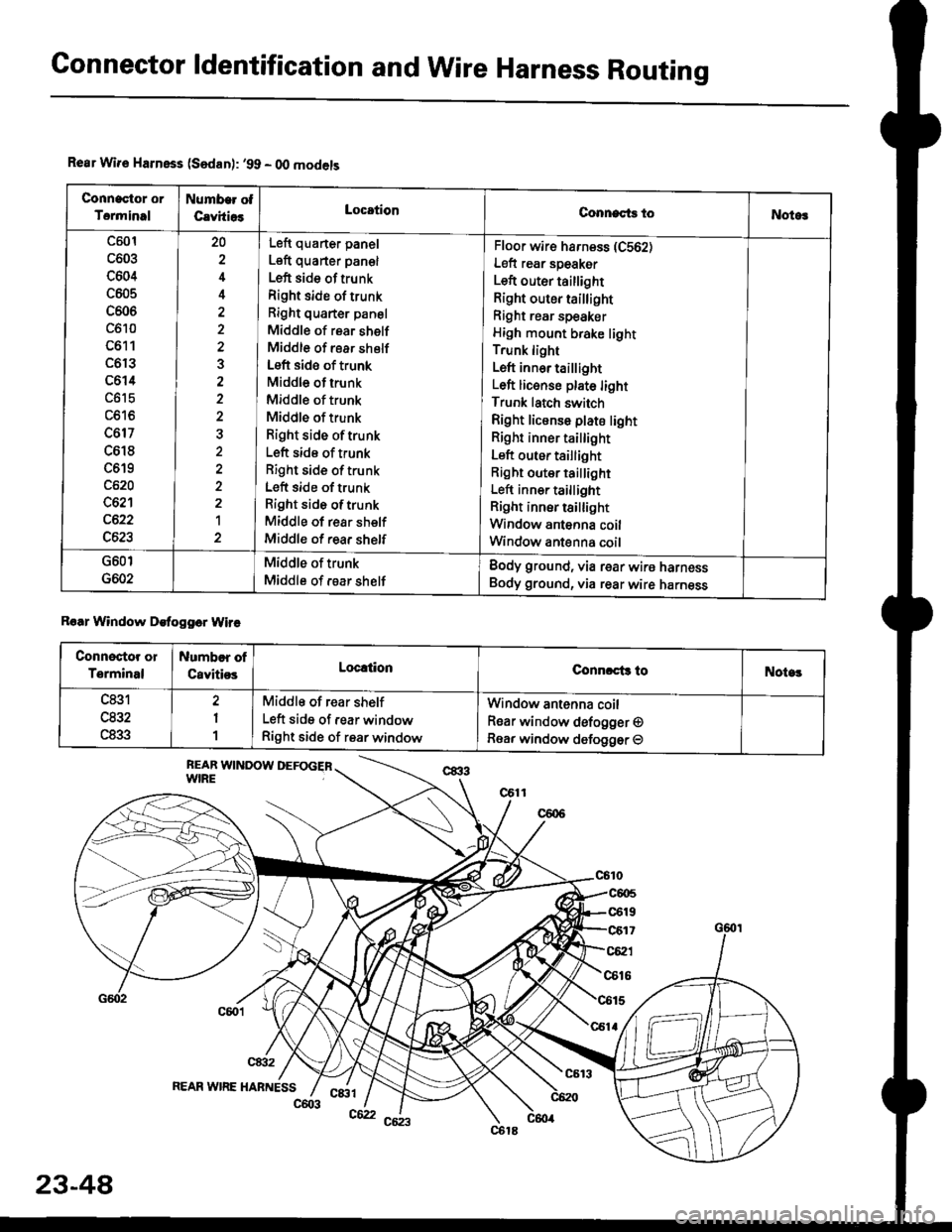
Connector ldentification and WireHarness Routing
Rear Wir€ Harnsss (Sedan): '99 - O0 models
Connactor or
Torminal
Numb€r ot
CavhiosLocationConnects toNotog
c501
c603
c604
c605
c606
c610
c611
c6r3
c614
c617
c618
c619
c620
c621
c622
c623
20
4
3
2a
1
Left quarter panel
Left quarter pan€l
Left side of trunk
Right side of trunk
Right quarter panel
Middle of rear shelf
Middle of rear shelf
Left side of trunk
Middle of trunk
Middle of trunk
Middle of trunk
Right side oftrunk
Left side of trunk
Right side of trunk
Left side of trunk
Right side oftrunk
Middle of rear shelf
Middle of rear shelf
Floor wir€ harness (C562)
Left rear speaker
Left outer taillight
Right outer taillight
Right rear speaker
High mount brake light
Trunk light
Left inn6r taillight
Left licenso plate light
Trunk latch switch
Right license plate light
Right inner tai ight
Left outer taillight
Right outer taillight
Left inner taillight
Right inner tsillight
Window antenna coil
Window ant€nna coil
G601
G602
Middle of trunk
Middle of rsar shelf
Body ground, via rear wire harness
Body ground, via rear wire harness
Roar Window Detogger Wire
Connectot or
Terminal
Numbor of
CavitiosLoc!tionConnrct3 toNote!
c831
u65Z
c833
2
1
1
Middle of rear shelf
Left side of rear window
Right side of rear window
Window antenna coil
Rear window defogger O
Rear window defogger O
REAR WIRE HABNESSc&tl
23-48
c603c62
Page 1612 of 2189
Fuel Gauge
Gauge/Sending Unit Test
!@ Do not smoke while working on tho fuel
system. Keep open tlame away trom your wotk atea.
NOTE: Refer to page 23-133 for the fuel gauge system
circuit.
'1. Check the No. 25 (7.5 A) fuse in the under-dash fuse/
relay box before testing.
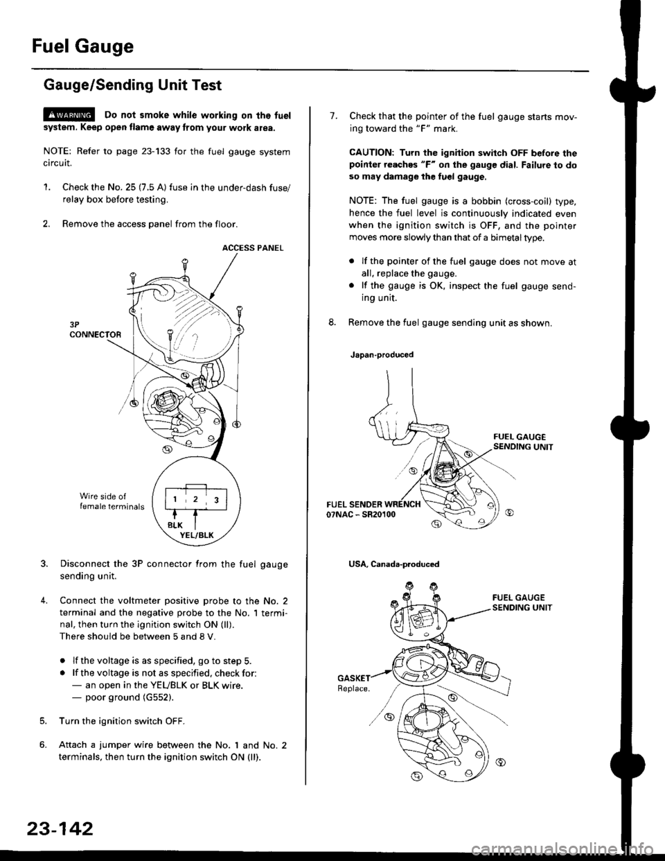
2. Remove the access panel from the floor.
ACCESS PANEL
Disconnect the 3P connector from the fuel gauge
sending unit.
Connect the voltmeter positive probe to the No. 2
terminal and the negative probe to the No. I termi-
nal, then turn the ignition switch ON (ll).
There should be between 5 and 8 V.
. lf the voltage is as specified, go to step 5.
. lf the voltage is not as specified. check for:- an open in the YEUBLK or BLK wire.- poor ground (G552).
Turn the ignition switch OFF.
Attach a jumper wire between the No. 1 and No. 2
terminals, then turn the ignition switch ON (ll).
)\
23-142
1.Check that the pointer of the fuel gauge starts mov-
ing toward the "F" mark.
CAUTION: Turn the ignition switch OFF before thepoinier reaches "F" on ihe gauge dial. Failure to do
so may damage the fuel gauge.
NOTE: The fuel gauge is a bobbin (cross-coil) type,
hence the fuel level is continuously indicated even
when the ignition switch is OFF, and the pointer
moves more slowly than that of a bimetaltype.
. lf the pointer of the fuel gauge does not move at
all, replace the gauge.
. lf the gauge is OK. inspect the fuel gauge send-
ing unit.
Remove the fuel gauge sending unit as shown.
Japan-produced
USA, Canada-produced
Page 1745 of 2189
Precautions/ Procedures
)General Precautions
r Carefully inspect any SRS part before you install it Do
not install any part that shows signs of being dropped
or improperly handled' such as dents, cracks or defor-
mation:
- Airbags- Cable reel
- SRS unit
-
Use only a digital multimeter to check the system lf
it's not a Honda multimeter, make sure its output ls
1O mA (0.01 A) or less when switched to the smallest
value in the ohmmeter range. A tester with a higher
output could damage the airbag circuit or cause acci-
dental deployment and possible injury'
I Do not install used SRS parts from another vehicle
When making SRS repairs, use only new pans'
) Except when performing electrical inspections'
always disconnect both the negative cable and posl-
tive cable from the battery, and wait at least three
minutes before beginning work
r Replacement of the combination light and wiper/
washer switches and cruise control switch can be
done without removing the steering wheel:
- Combinalion light and wiper/washer switch replace
ment, see section 23
- Cruise control sevresume switch replacement' see
section 23.
. Whenever the ignition switch is ON {ll), or has been
turned OFF for less than three minutes' be careful not
to bump the SRS unit; the airbag(s) could accidental-
ly deploy and cause damage or injury'
. Whenever the airbag{s) has(have) been activated'
replace the SRS unit.l,
2+7
Airbag Handling and Storage
Do not try to disassemble the airbag assembly. lt has no
serviceable parts Once an airbag has been operated
(deployed). it cannot be repaired or reused'
For temporary storage of the airbag assembly during ser-
vice. olease observe the following precauttons:
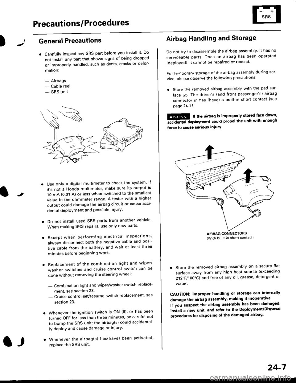
. store the .emoved airbag assemblv with the pad sur-
face uo The driver's (and front passenger's) airbag
connecto''s'-as {have) a built.in short contact (see
page 2a-l 1
: | ..r r-+r-a k imninncrlv slorcd lace down,-""dd.r6t dtatltt-,tl could propel the unit whh enough
force lo c.usa 3a.ix! intury
AIRBAG CONNECTORS(With built in shon contact)
. Store the removed airbag assembly on a secure flat
surface away from any high heat source {exceeding
212"FI1OO"CJ and free of any oil' grease, detergent or
water.
CAUTION: lmproper handling or storage can intern'lJy
damage the airbag assembly, making it inoperativo
lf you suspect the airbag assembly has been dam€cd'
inslall a new unit. and relsr lo the Deployment/DisPG'l
olocedules for disposing ol the damaged airbag
Page 1841 of 2189
Ground
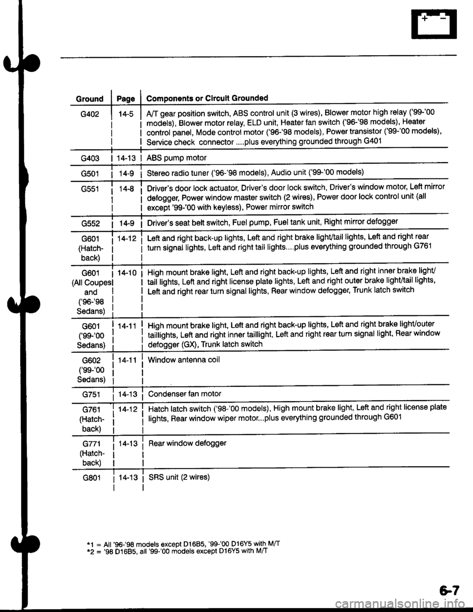
G402
Components or Clrcult Grounded
Arr gear position switch, ABS control unit (3 wires), Blower motor high relay ('99-'00
models), Blower motor relay, ELD unit, Heater Jan switch ('96-'98 models), Heater
control panel, Mode control motor ('96.�98 models), Power transistor ('99-'00 models),
Service check connector....plus everything grounded through G401
| 14-13 | ABS pump motor
1l-9 i Stereo radio tuner ('96-'98 models), Audio unit ('99-'00 models)
Drivsr's door lock actuator, Driver's door lock switch, Drivefs window motor' Left mirror
defogger, Pow€r window master switch (2 wires), Power door lock control unit (all
except '99-'00 with keyless), Power mirror switch
G55214-9 i Driver's s€at belt switch, Fuel pump, Fuel tank unit, Right mkror defogger
G601
(Hatch-
back)
14-12 iLeft and right back-up lights, Left and right brake lighvtail lights, Lefl and right rear
turn signal lights, Left and right tail lights....plus eveMhing grounded through G761
G601 I 14-10
(All Coupesl
ano
(96198
S6dans)
High mount brake light, Left and right back-up lights, Left and right inner brake lighv
taiilights, Lett and right license plale lights, Lett and right outer brak€ lighvtail lights'
Left and right rear turn signal lights, Rear window deJogger, Trunk latch switch
G601
(99-'oo
Sedans)
G602
('ss-'00
Sedans)
G761
(Hatch-
back)
G771
(Hatch-
back)
14-11
14-12 i
High mount brake light, Left and right back-up lights, Left and right brake lighvouter
taillights, Left and right inner taillight, Left and right rear turn signal light' Rear window
deJogger (GX), Trunk latch switch
Window antenna coil
Hatch latch switch ('98-'00 models), High mount brake light' Left and right license plate
lights, Rear window wiper motor...plus everything grounded through G601
Rear window defogger
14-13 i SRS unit (2 wires)
*1 = All '96-98 models €xcept Dl685, '99100 D16Y5 with M/T*2 = '98 D1685, all '99-'00 models except Dl6Y5 with M/T
e7
Page 2018 of 2189
Power Windows (contd)
- How the Circuit Works
CAUTION: You could iniure your arms, hands, or
fingers if you unintentionally switch the driver's
window to "automatic down" while working in
that door with the power on. Disconnect the
window switch conneclot or the battery when
working in the driver's door.
System Description
The operation of the power windows is controlled by
the main switch in the power window master switch.
When the main switch is in OFF, only the driver's door
window can be opened or closed. With the main
switch ON, all windows can be ooened or closed
either by swtches in the master panel, or swttches in
the doors. The driver's window switch also has an
automatic down mode which is tumed on by pushing
the switch down to its second oosition.
The power windows are driven by reversible motors.
Each motor is protect€d by a built-in circuit breaker.
lf the window switch is held on too long (with the
window obstructed, or after the window is fully up or
down), the circuit breaker opens the circuit. The
circuit breaker resets automaticallv as it cools.
Driver's Window
With the ignition switch in ON, voltage is provided to
the coil of the power window relay through fus€ 24.
The contacts of the power window relay close, and
voltage is applied to the driver's switch. When you
push the power window master switch to UP, voltage
is applied to the driver's window motor. (The motor's
ground path is back through the master power
window switch.) The driver's window motor then
drives the window up. When you push the switch to
DOWN, voltage is applied in the opposite direction
and the motor drives the window down.
Automatic Down (Driver's Window)
With the ignition switch in ON or START, voltage is
applied to the coil of the power window relay. The
contacts of the power window relay close and
voltage is applied lo the power window master
switch. When you push the driveas switch to the
AUTO DOWN position, voltage is applied through
the driver's switch to the driver's window motor. The
control unit receives pulses at the pulser input while
the motor is running. When the window is fully
down, the motor stops, and pulses are no longer
generated by the pulser. This is sensed by the
control unit at the pulser input, and voltage is no
longer applied to the driver's window motor.
Passenger Windows
With the ignition switch in ON, voltage is applied to
the coil of the power window relay through fuse 24.
The contacts of the power window relay then close,
applying voltage to the individual window switches
and the power window master switch. With the
master panel main switch ON, the passenger
windows can be ooerated from the individual
window switches or from tho master panel switches.
When you push the front passengsr's window
switch to UP, voltage is applied to the f ront
passenger's window motor. (The motor is grounded
through the contacts in the front passenger's
window switch and the oower window master
switch.) The window moves up as long as you hold
the switch in the UP position. lf you push the switch
to DOWN, voltage is applied in th€ opposite
direction to the front passenger's window motor, and
the window movss down as long as you hold the
switch in the DOWN Dosition. The window switches
in the other doors operate similarly.
When you push the front passenger's switch in the
master panel to UP, voltage is applied through the
front passenger's window switch contacts to the
front passengefs window motor. (The motor is
grounded through the contacts in the front
passenger's window switch and the power window
master switch.) The window moves up as long as
you hold the switch in the UP position. lf you push
the switch to DOWN, voltage is applied in the
opposite direction to lhe front passenger's window
motor, and the window moves down as long as you
hold the switch in the DOWN position. The other
passenger window switches in the master panel
operate similarly.
Refer to the Service Manual (Section 23, Electrical)
for specific tests or troubleshooting procedures.
120-4
Page 2099 of 2189

Component Location
109. Underside of Hatch Lid ('96-'97 Models)112. Right Side of Cargo Area (Hatchback)\
\,
110. Underside of Hatch Lid113. Center of End Panel
111. Behind Left Side of Dash Panel1'14. Lett Side of Trunk Lid (with Optional Trunk Spoiler)
201 -18
\,
Page 2111 of 2189
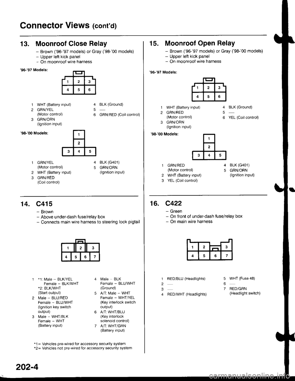
Connector Views (cont'd)
13. Moonroof Close Relay
'96-�97 Models:
1 WHT (Battery input)
2 GRN//EL
{Motor conirol)
3 GRN/ORN(lgnition lnput)
- Brown ('96-'97 models) or Gray ('98-'00 models)- Upper left kick panel- On moonroof wire harness
5
6
BLK (Ground)
GBN/RED (Coilconkol)
'98r00 Models:
GRN/YEL(Motor control)
WHT (Battery input)
GRN/RED(Coil control)
4 BLK (G401)
5 GRN/ORN(lgnition input)2
3
15. Moonroof Open Relay
- Brown ('96-'97 models) or Gray ('98-'00 models)- Upper left kick panel- On moonrool wire harness
'96.�97 Models:
1 WHT (Battery input)
2 GRN/FED(lvlotor control)
3 GRN/ORN(lgnition input)
'98r00 Modelsi
BLK (Ground)
YEL (Coil conkol)
5
6
GBN/RED(lvlotor control)
WHT (Battery input)
YEL (Coil control)
4 BLK (G401)
5 GRN/ORN(lgnition input)2
3
,1^t
6
14. C415
- Brown- Above underdash fuse/relay box- Connects main wire harness to steering lock pigtail
* 1: [,4ale BLKryELFemale - BLKMHT*2: BLK,/WHT(Start oulput)
l\.4ale - BLU/REDFemale - BLUruVHT(lgnilion key switchoutpur)
N4ale - WHT/BLKFemale - WHT(Battery input)
l\,4ale BLKFemale - BLU^VHT(Ground)
Ani Male - WHTFemale - WHT /EL
(Key interlock switchourpur)
A/T:WHT/BLU(Key interlocksolenold control)
A"rT: WHT/GRN(Battery inpul)
*1= Vehicles pre-wired for accessory security system*2= Vehicles not pre wired for accessory security system
202-4
16. C422
- Green- On tront ol under-dash tuse/relay box- On main wire harness
7
l
2
3
4
5
6
7
FED/BLU (Headlights)
REDAVHT (Headlights)
WHT (Fuse 48)
BED/GRN(Headlight switch)
Page 2143 of 2189
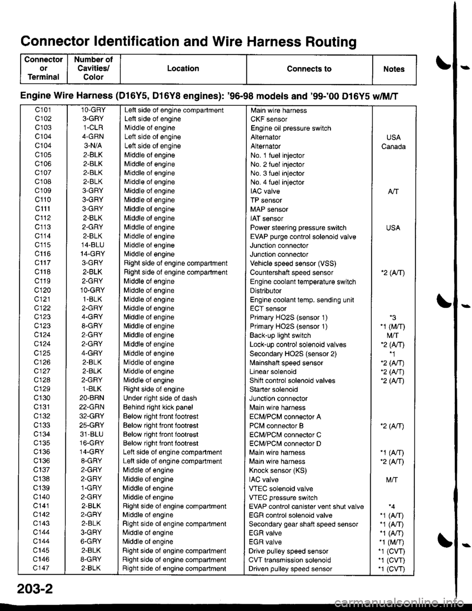
Connector ldentification and Wire Harness Routing
Connector
or
Terminal
Number ot
Cavities/
Golor
LocationConnects toNotes
Engine Wire Harness (Dl6Y5, D16Y8 engines): '96-98 models and '99;00 D16Y5 dM/T
c101
c102
c 103
c104
Q104
c105
c106
c107
cl 08
cl09
cl10
c1l1
cl'12
c113
c114
c'115
c116
c'117
c 118
c119
c120
c121
c122
c123
c123
c124
Q124
c125
c 126
c127
c128
c129
c130
c131
cl32
c 134
c135
c136
c137
c138
c139
c'140
c141
c142
c143
c144
c'|44
c145
c146
c147
1O-GRY
3.GRY
1-CLR
4-GRN
3-N/A
2-BLK
2-BLK
2-BLK
2-BLK
3-GRY
3-GRY
3-GRY
2.BLK
2.GRY
2-BLK
14-BLU
14-GRY
3.GRY
2-BLK
2-GRY
1O-GRY
1.BLK
2.GRY
4-GRY
8-GRY
2-GRY
2.GRY
4-GRY
2.BLK
2.BLK
2-GRY
1.BLK
2O.BRN
22.GRN
32.GRY
25.GRY
31-BLU
16.GRY
14-GRY
8.GRY
2-GFIY
2.GRY
1-GRY
2-GRY
2-BLK
2-GRY
2.BLK
3-GRY
6-GRY
2.BLK
8-GRY
2-BLK
Left side of engine compartment
Left side of engine
Middle of engineI att .i.la ^f an^i^6
Left side ot engine
Middle of engine
Middle of engine
Middle of engine
Middle of engine
Middle of engine
[,liddle of engine
Middle ot engine
Middle ot engine
Middle of engine
Middle of engine
Middle of engine
l\,liddle of engine
Right side of engine compartment
Right side of engine compartment
Middle ot engine
Middle of engine
Middle of engine
Middle of engine
l\,liddle of engine
Nliddle of engine
Middle ot engine
Middle of engine
Middle ot engine
Middle of engine
Middle of engine
Nliddle of engine
Right side of engine
Under right side of dash
Behind right kick panel
Below right front footrest
Below right front footrest
Below right front footrest
Below right front tootrest
Left side ot engine compartment
Left side of engine compartment
Middle of engine
liliddle ot engine
Middle of engine
Nriddle ol engine
Right side of engine compartment
Middle ol engine
Right side of engine compartment
Middle of engine
N,liddle of engine
Right side of engine compartment
Right side of engine compartment
Bight side of engine compartment
Main wire harness
CKF sensor
Engine oil pressure switch
Alternator
Alternator
No. 1 fuel injector
No. 2 fuel injector
No. 3 fuel injector
No.4 fuel injector
IAC valve
TP sensor
MAP sensor
IAT sensor
Power steering pressure switch
EVAP purge control sol€noid valve
Junction connector
Junction connector
Vehicle speed sensor (VSS)
Countershatt speed sensor
Engine coolant temperature switch
Distributor
Engine coolant temp. sending unit
ECT sensor
Primary HO2S (sensor '1)
Primary HO2S (sensor '1)
Back-up light switch
Lock-up control solenoid valves
Secondary HO2S (sensor 2)
lvlainshafl speed sensor
Lanear solenoid
Shift control solenoid valves
Starter solenoid
Junction connector
Main wire harness
ECM/PCM connector A
PCM connector B
ECM/PCNI connector C
ECM/PCl\,,| connector D
Main wire harness
Maln wire harness
Knock sensor (KS)
IAC valve
VTEC solenoid valve
VTEC pressure switch
EVAP control canister vent shut valv€
EGR control solenoid valve
Secondary gear shatt speed sensor
EGR valve
EGR valve
Drive pulley speed sensor
CVT transmission solenoid
Driven pulley speed sensor
USA
Canada
AlT
USA
'2( tr\
'3
-1 (M/r)
t\4/T'2 (Anl'1
'2 (An)'2 (Nr)'2 (AtT)
'2 (Atr)
-1 (An)-2( fi|
M/T
.1 (Arr).1 (A,T)"1 (A/r)-1 (M/r).1 (CVT),1 (cw)'1 (CVT)
203-2