1999 HONDA CIVIC engine
[x] Cancel search: enginePage 1817 of 2189

Contents
How to Use This Manual ICircuit Schematics (see Circuit Index)Fuse/Relaylnformation 6Ground-to-Componentslndex 6-6ComponentLocationPhotooraohs 201Conriector Views 202
Circuit Index
Accessory power socket 155Air conditionerAir delivery'96198 models 61'99-'00 models 61-2Blower controls'96198 models 60'99100 models 60-1Compressor controls 62Fans 63Anti-lock brake system (ABS) 44A/T gear position indicatorCVT 89All except CVT 89-1Automatic transmission controlsAll '96-'98 models except CVT and GX 39All '99100 models except CVT 39-8All GX models 39-8'96-'�98 CVT 39-4'99100 cw 39-12Back-up lightsCoupe and Sedan 110Hatchback l'10-1Brake lightsAll Coupes and'96-'98 Sedans 110-15'99-'00 Sedans 110-16Hatchback 110-17Brake system indicator light'96198 models 7'1'99100 models 71-1Ceiling light 114-3Charging system 22Condenser fan 63Console lights 114Cruise control 34Dash lights 114Daytime running lights 110- 13Engine coolant temperature gauge 81-1Fog lights 110-10Front parking lights 110-2Fuel gauge 81-1Fuse/relay boxUnder-dash 6Under-hood 6-4Underhood ABS 6-3Gauges 81Ground distribution 14Ground-to-Componentslndex 6-6Hazard warning lightsAll except '99100 Sedans 110-6'99100 Sedans 110-8Headlights 110-12Headlight switch 100Heater - See Air ConditionerHorn'96197 models 40'98 model 40-1'99100 models 40-2lgnition key reminder 73lgnition systemAll '96198 models except Dl685 20All '99100 models except D16Y5 with Mn 2O-2All D1685 engines 20-2'99-'00 D 16Y5 with M/T 20
lndicators 80Integrated control unit 70lnterlock systemAll except'96J98 CVT 138'96198CVT 138-1License plate lightsAll Coupes and '96-'98 Sedans I l0-3'99100 Sedans 1 10-4Hatchback 110-5Low fuel indicator light 74Moonrool'96197 models |22'98-'00 models 122-1Odometer 81Oil pressure indicator light 80-3Power distributionBattery to ignition switch, fuses, and relaysFuses to relays and components 10-2Power door locksAll models without keyless entry 130'96-'98 models with keyless entry 130-2'99100 models with keyless entry 130-12Power mirrorsWithout detogger 141With defogger '141-2
Power windows 120Programmed fuel injection system (PGNr-Fl)All '96-98 models except D1685 23All '99-'00 models except D16Y5with M/T and D1685 24All D1685 engines 25'99100 D16Y5 with M/T 23Radiator fan 63Rear window defogger'96-,98 models 64'99100 models 64-1Seat belt reminder 73Security system'96.'98 USA HX, LX, EX 133'96-'98 Canada EX, Si 133'99TOO USA HX, LX, EX, DX.V Si 133-4'99100 Canada EX, Si 133-4All CX and DX models 133-8Speedometer 81Starting systemA./T (All except Dl685) 21A"/r (D16Bs) 21-1Manualtransmission 21-2Slereo sound system 150Supplemental rastraint system (SRS) 47Tachometer 81TailliqhtsAllboupes and'96-'98 Sedans 110-3'99100 Sedans 1 10-4Hatchback 110-5Trunk light 114-3Turn signal lightsAll except'99100 Sedans 110-6'99-'00 Sedans 1 10-8Vehicle speed sensor (VSS) 33Wiper/washerFront 91Rear 92
10
Page 1824 of 2189
Connector Views
To see the configuration of a connector's cavities, look up its view number in the Connector
View section in the back of the book. Each view includes the color of the connector, where it
is located, and what it connects to.
Use the Connector Views to help locate the proper cavity when you need to probe a
connector. lt can be especially helpful if the connector has more than one wire of the same
cotor.
Connector views can also be used to help diagnose multiple symptoms in separate circuits
which could be caused by a single problem in a connector shared by those circuits. Here's
how:
1. Pick one of the multiple symptoms and look up the schematic for that circuit.
2. Make a list of all the in-line and fuse box connectors in that schematic (include page
numbers).
3. Then, in the Connector View section, look up each connector on your list to see il circuits
related to the other symptoms run through one of them. lf they do, inspect that connector
for the oroblem.
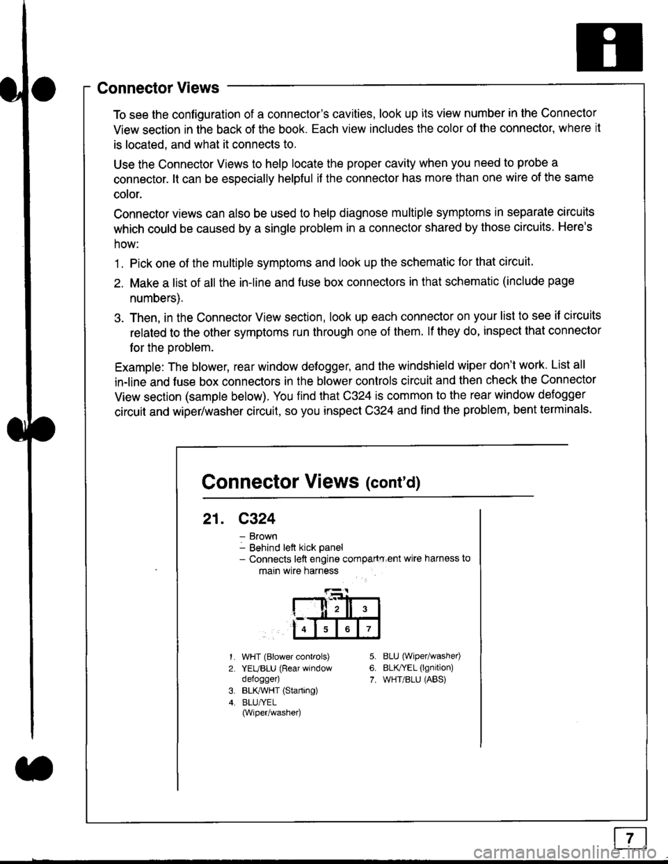
Example: The blower, rear window defogger, and the windshield wiper don't work. List all
in-line and fuse box connectors in the blower controls circuit and then check the Connector
View section (sample below). You find that C324 is common to the rear window defogger
circuit and wiper/washer circuit, so you inspect C324 and find the problem, bent terminals.
5.
6.
7.
1.
2.
WHT (Blower controls)
YEUBLU (Rear window
defogger)
BLK,ryVHT (Starting)
BLU/YEL(Wiper/washe0
8LU (Wiper/washed
BLfiEL (lgnition)
WHT/BLU (ABS)
Connector Views (cont'd)
21. C324
Brown
Behind left kick panel- Connects left engine compartry'ent wire harness to
main wire harness
ll,ll,
567
Page 1829 of 2189
In the "OHMS" range, the DVOM will measure
resistance between two points along a circuit.
Low resistance means good continuity.
Diodes and solid-state devices in a circuit can
make a DVOM give a false reading. To check
a reading, reverse the leads, and take a
second reading. lf the readings differ, the
component is affecting lhe measurement.
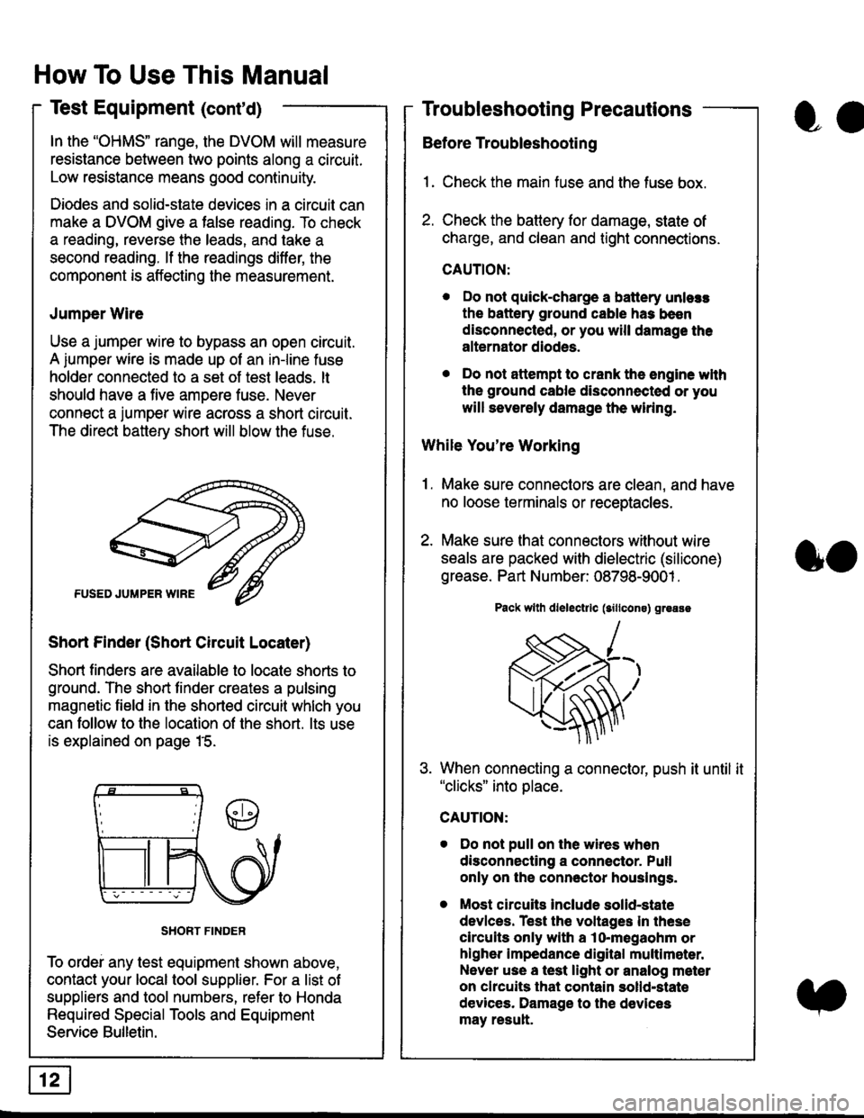
Jumper Wire
Use a jumper wire to bypass an open circuit.
A iumper wire is made up ot an in-line fuse
holder connected to a set of test leads. lt
should have a five amoere fuse. Never
connect a jumper wire across a short circuit.
The direct battery short will blow the fuse.
Short Finder (Short Circuit Locater)
Short finders are available to locale shorts to
ground. The short tinder creates a pulsing
magnetic field in the shorted circuit whlch you
can follow to the location of the short. lts use
is explained on page 15.
SHORT FINDER
To ordei any test equipment shown above,
contact your local tool supplier. For a list of
suppliers and tool numbers, refer to Honda
Required Special Tools and Equipment
Service Bulletin.
How To Use This Manual
Test Equipment (cont'd)
oa
Troubleshooting Precautions
Before Troubleshooting
1. Check the main fuse and the fuse box.
2. Check the battery for damage, state of
charge, and clean and tight connections.
CAUTION:
. Do not quick-charge a battery unlers
the battery ground cable has been
disconnected, or you will damage the
alternator diodes.
. Do not attempt to crank the engine wlth
the ground cable disconnected or you
will severely damage the wiring.
While You're Working
1. Make sure connectors are clean, and have
no loose terminals or receptacles.
2. Make sure lhat connectors without wire
seals are packed with dielectric (silicone)
grease. Part Number: 08798-9001 .
Pack wllh dlelectrlc (sillcons) greass
When connecting a connector, push it until it"clicks" into place.
Do not pull on the wires when
disconnecting a connector. Pull
only on the connector houslngs.
Most circuits Include solid-state
devlces. Test the voltages In these
circuits only with a lo-megaohm or
higher impedance digital multlm6ter.
Never use a test light or analog meter
on chcuits that contain solld-state
devices. Damage to the devices
may result.
oo
Page 1838 of 2189
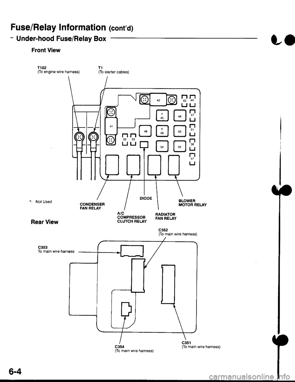
Fuse/Relay Information lcont'd)
- Under-hood Fuse/Relay Box
Front View
T'102(To engine wire harness)
LO
T1Oo starter cables)
*: Not Used
Rear View
c353To main wire harness
DE
tr
tr
tr
t-l
IJ
n
tJ
t-l51
IJ
n
IJ
n5T
IJ
[[o main wire harness)
6-4
ffo main wire harness)fto main wire harness)
Page 1840 of 2189

Ground-to-Components I ndex
f.,lONOTE: All ground wires are BLK unless otherwise noted.
GroundPageComponents or Circuit Grounded
Battery (BLKYEL)
Steering pump bracket
t+-rg ITransmission housing
l
G101
(-1)
G101
(-2)
14-2
and
14-3
ano
14-1
Powertrain or engine control module (PG1 and pG2 are BLK: LG1 and LG2 are
BRN/BLK), EGR control solenoid valve (CW, EGR valve and lift sensor (Dt6yS enginewith M,/T), Engine coolant temperature switch, pGM-Fl main relay, power steeringpressure switch (USA), Primary HO2S (D16Y5 engine with l\/,/T), Vehicle speed sensor,VTEC pressure switch (D16Y5/D16Y8 engines), CKF sensor (BRN/BLK), Transmission
control module (CYf) (Pc1 is BLK: LG1 is BRN/BLK)
Shielding betvveen the PCM or ECM and these components (all have BRN/BLK wires):
CKF sensor, TDC/CKP/CYP sensor. Primary and secondary heated oxygen sensors.
Knock sensor (CWDl6YB engine), Mainshaft speed sensor (AiT except CVT),
I Countershaft speed sensor (A/T except CVf)
Shielding between the TCM and these components (CVT) (all have BRN/BLK wires):
Drive pulley speed sensor, Driven pulley speed sensor, Secondary gear shaft
speed sensor
Powertrain or engine control module (PG1 and pG2 are BLK; LG1 and LGz are
BRN/BLK), EGR control solenoid valve (D16Y5 engine), EGR valve (Dt685), Engine
coolant temperature switch, Fuel pressure regulator shut-off solenoid valve (D1685),
PGM-FI main relay, Power steering pressure switch (USA), Vehicle speed sensor, VTECpressure switch (All except D16Y7 engine), CKF sensor (A
except 81642) (BRN/BLK)
Shielding between the PCM or ECM and these components (all have BRN/BLK wires):
CKF sensor, TDC/CKP/CYP sensor, Primary and secondary heated oxygen sensors,
Knock sensor (All except D16Y7 engine), i/ainshaft speed sensor (Arf except CW),
Countershaft speed sensor (A,/T except CVf), Drive pulley speed sensor (CW), Drivenpulley speed sensor (CVT), Secondary gear shaft speed sensor (CVf)
I Badiator fan motor, Right front parking/turn signat tight, Right headtight
G20214-4I Cruise control actuator, Left front parking/turn signal lights, Left headlight, Rear window
I washer motor, Windshield washer motor, Washer fluid level switch (,99-'00 Canada)
G401| +-o
and
14-7
Accessory power socket, Brake fluid level switch, Clutch interlock switch (M/T), Clutchswitch (lillT with cruise/D16Y5 engine with MfD, Combination wiper switch (Z wires),
Cruise control main switch, Cruise control unit, Dash lights brightness controller, Data
link connector, Daytime running lights control unit (Canada), Gauge assembly, Horn('96-'97 models), Integrated control unit, Interlock control unit (ArI), Keyless door lock
control unit ('99-'00 models with keyless), Moonroof close and open relays, Moonroof
switch, Park pin switch (A/r), Power window relay, Rear window defogger relay, Rear
window defogger switch ('96-'98 models), Steering lock, Stereo radio tuner (,96-,98
USA: LX, EX, and HX), Turn signal/hazard relay, Windshield wiper motor.....plus
everything grounded through G402
6-6
Page 1847 of 2189
'1 = '96 D16Y8 engine: All coupes'97 D16Y7 engine: California Coupe, California Sedan LX'97 D16YB engine: All coupes, California Sedan'98100 models: All except D1685-.t UNDER-DASHI
I
\
'--1 $NEGRATED
| !s$il:'Ptlofo avtEw 67
c42'lPHO|O 63vlEW 50
ct01
vtEw28
FUSE/RELAYBOX
\
I
T
D16Y8
13
c568
ELKAYTIT
BLKAVHT
1
143
EVAP BYPASS : :SOLENOIDVALVE . ,Page 23-9,23-11,23-14,24-7,' '
24-9, ot 24-11
H02SPage 23-11ot 24-11pHoTolo4 ; ; PHoTo 43(See S/lV page 11-9lor'99-'00 models) ,
i1[
":"[-lT:T
l+Tli'::f;:r i"'{' l;;;]fip;:
I Fs'[
**,
I il i I ii !-l s];$:i i Ii t--l
i ! i'*[ iEi.;*Ti lii
'fl*-i
i li itqii-*
i l il[l?ti
lii iiii;:" i:li
i trr i I i.r^.:.'.'.'i::::;j i !' i
: i i , I i ,+e;::"," i : ! i
itI
i! | i | :".*lfigi3li;ts's"";:tg;u'u^.i : ! :
iv7"-- : rA : *'I i i osl :
; CoNTBOL , r--1
i liiit- i i_j i i_j #s,{;'i' i [__j
ffnih'*'
i 23:11,23-t4, , EVAP PURGE I pRtMARy Ho2s : ' powERTRAtN :| 24-7,24-9, ' CONTFOL ; Page 23-8, 23'10, 23'13, , ; CONTROL ,' ot 24-11 ' SOLENOIO , 24-7 .24-8. 24-10. ot 25-8 ' , MOOULE (PCM) ,' pHoTo 3s : VALVE I PHoro 40 ' ' Paqe 39-8 '
| (see s/M : Pase23-s,23'11, : ii3l311l l3;ll Pl?191,.,"^,, : ' orSe-12 :
' PHoTo 39 I vALvE | ' Paqe 39-6
: (See S/M : Page 23-9, 23'11. ' lHqI94?199 99 0.16Y!i - i ' or 5g-tz :i bi-gllt-g i zs:tq, zc-i, zc-g', ' PHoro 733 ree 00 D16Y8/816A2) i '. in6i "i i
:':1T:9' ',91"?i'l; i------ ------j ".-':-*-'1. -----j(cont'd)- - - -::-:-l - - - - t PHO\O 37 to16Y7l
1(}5
Page 1852 of 2189
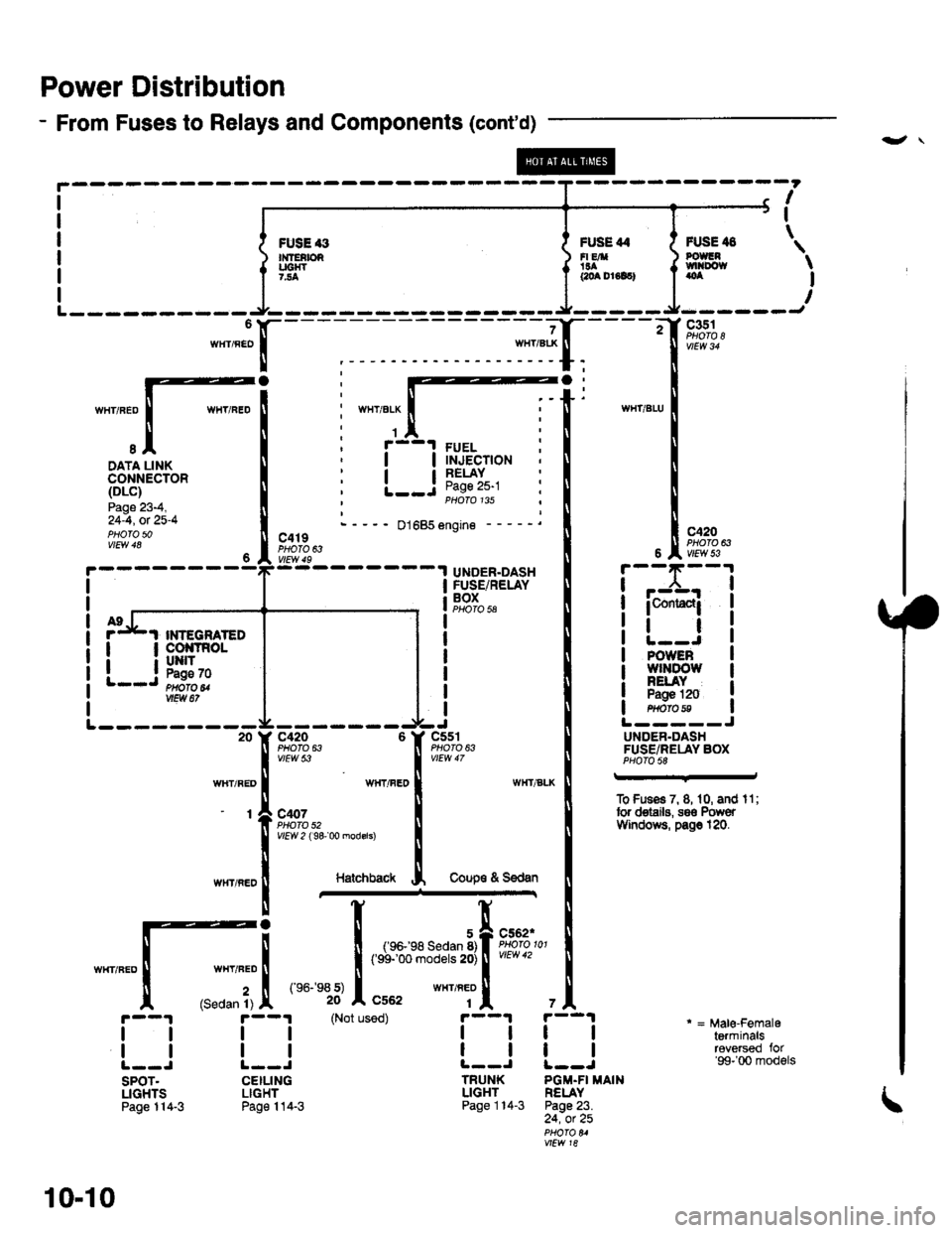
Power Distribution
- From Fuses to Relays and Components (cont'd)
-",JX-
I
I
\FUSE '3n{fEtbRUC|{T7.'.4
FUSE 44FI EA'!aacoa Dr6lc)
FUSE il8POUGNtvtl|Do{taoa
c351
c420PHOTO 63
I-.:CrJ
WIIT/ELX
1
I
I
I
I
FUELINJECTIONRELAYPage 25-1PHOTO 135
DATA LINKCONNECTOR(DLc)
Page 23-4,24-4, ot 25-4PHOfO 5001685 engine -
c419PHOTO 63
UNDER.DASHFUSE/RELAYBOXPHO|Q 5A
POWEBw]tDowNELAYPagE 120H$fa8
L-- ----- --20
wlIT/RED
-t
c420 6PHO|O 63vtEw 53
WHT/FEO
c407PHOTO 52Y|EW 2 ( 9& 00 modsrs)
c5s'rPHO|O 63
L-----JU DEN.DASHFUSE/RELAY BOXPHOfO 58
To Fuses 7, 8, 1 0, and I 1 ;tor deiails, s8€ PowerVYindotts, pa$ 120.
HatchbackCoup€ & S€dan
WHT/FED
(Sedan 1)
(e6-
101
,,, tr:::--*''.:lltut
(Not used)
i--l
tlL--J
TRUNKLIGHTPage 114-3
tl
tl
SPOT.LIGHTSPage 114-3
tl
tl
CEILINGLIGHTPage 114-3
* = Male-Femaleterminalsreversed for'99-'00 models
7A
tl
tl
PGM-FI MAINRELAYPage 23.24, ot 25
vtLw 18
I
I
PGM-FIRELAYPage 2324, ot 22
vtLw 18
i-,-x;-l
icontac{i
tlINTEGNATED
l__i!ffi*
10-10
Page 1853 of 2189
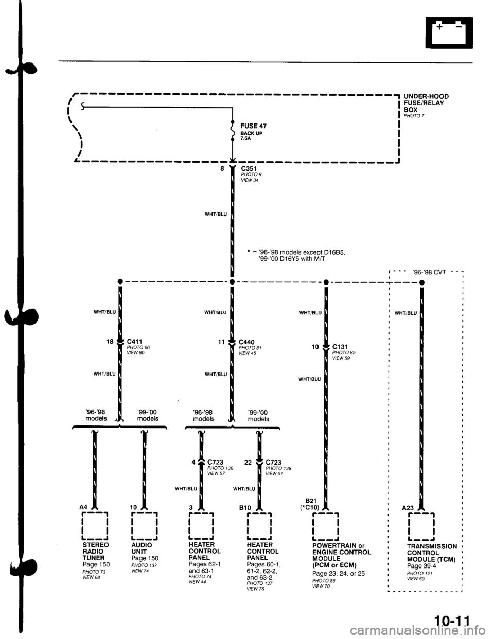
* = '96-98 models except D1685,'99100 D16Y5 with lVl/T
UNDER-HOODFUSE/RELAYBOX
'98CW - -.
, r--1
:ll:,tt:
: r--J ;, TRANSMISSION ,. CONTROL' MODULE OCM) :' Page 3g-4 ;I PHOIO 121I vlEW 69
I
I
\FUS€ 47aAcx uP
c351
WHT/BLIJ
WHT/BLU
WHT/BLU
18c4'l t
vlEw 60
WHT/ALU
WHT/ALU
11c440
WHT/BLU
10
' WHT/BLU
, 423
c131
vtEw 59
WHT/BITJ
'96-'98
models
I
tl
tl
STEREORADIOTUNERPage 150
'99-'m
modelsmodeB
'99-'�00
models
c723c723
vtEw 57
wHr/atu
810B�21cc10)
tl
ll
HEATERCONTROLPANELPages 60-1,61-2,62-2,and 63-2
vtEw 76
tl
tl
POWERTRAIN oTENGINE CONTROLMODULE(PCM or ECM)
Page 23, 24, ot 25
AUDIOUNITPage 150
tl
HEATERCONTROLPANELPages 62-1and 63'1
10-1 1