Page 1300 of 2189

Dashboard
Gomponent Removal/lnstallation
(cont'd)
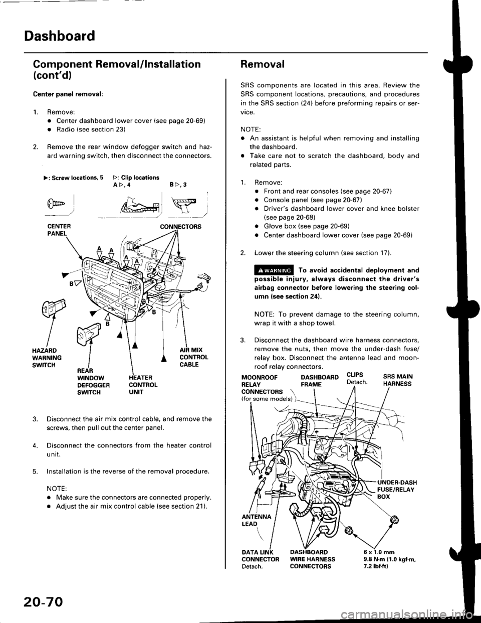
Center panel removal:
1. Remove:
. Center dashboard lower cover (see page 20-69)
. Radio {see section 23)
2. Remove the rear window defogger switch and haz-
ard warning switch, then disconnect the connectors.
>: Screw locations, 5 >: Clip locationsA>,4 B>,3
fii*-)
CENTERPANEI.
rt-xR.
W
IHAZARDWARNINGswlTcH
r44 "
F.IZvl
IIREARwtNoowOEFOGGERswtrcH
MtxCONTNOLCABLE
3. Disconnect the air mix control cable, and remove the
screws, then pull out the center panel.
4. Disconnect the connectors from the heater control
u nit.
5. Installation is the reverse of the removal procedure.
NOTE:
. Make sure the connectors are connected properly.
. Adjust the air mix control cable (see section 21).
20-70
Removal
SRS components are located in this area. Review the
SRS component locations, precautions, and procedures
in the SRS section (24) before preforming repairs or ser-
vice.
NOTE:
. An assistant is helpful when removing and installing
the dashboard.
. Take care not to scratch the dashboard, body and
related parts.
1. Remove:
o Front and rear consoles (see page 20-67)
. Console panel (see page 2O 67),
. Driver's dashboard lower cover and knee bolster(see page 20-68)
. Glove box (see page 20-69)
. Center dashboard lower cover (see page 20-69i
2. Lower the steering column (see section 17).
@ To avoid accidental deplovment and
possible injury, always disconnect the driver's
airbag connector belore lowering the steering col-
umn lsee section 241.
NOTE: To prevent damage to the steering column,
wrap it with a shop towel.
3. Disconnect the dashboard wire harness connectors,
remove the nuts, then move the under-dash fuse/
relay box. Disconnect the antenna lead and moon-
roof relay connectors.
DASHBOARD cltPs
CONNECTORS(for some models)
MOONROOFRELAY
ANTENNALEAO
FRAME
SRS MAINHARNESS
9.8 N.m (1.0 kgf m,7.2lbt.ltl
DATACONNECTOR WIRE HARNESSDetach. CONNECTORS
Page 1378 of 2189
Circuit Diagram
'96 - 98 Models
LINDEF NoOD FUSETFELAY 30x
WNTTBLK +WFT
8L|(YEi
LIGHT
Y
I
No1l lS0Al Ni42 (40A)
S;rt' | | lieti{,**i'-t L-:} [:] | h
crca(.-A-o \1 \-r. \-r-1 \'\
!9[1' ? _?__?'? _t__?__t
21-4
Page 1379 of 2189
'99 - 00 Models
UNDER,HOOO FUSE/RELAY 8OX
PUSN SWITCH
lHce nvosrar F)- aLu neo(Wirh IVC)
DASH LIGHTS -/1BBTGNTNESS < l- FEoCONTROLLER -!
IGN TION SW TCHUNDEF DASHFUSElRELAY BOX
**,',,* **",@ ",.
@f
u,n,",,
ELUAVHT
I
YBLUi BtK
BLOWERMOTOR
ELOWERMOTORHIGHRELAY
PNK/BLK
FED''WHT
RED,YEL
GRY
BRN
YEL
YEL/FEO
6RNiYEL
8LU/!VHT
YEL/BLU
BRNfiHT
GFNM/HT
GRNi FED
O :8P CONNECTOR
! :20P CONNECTOF
E : 12P CONNECToR
BLUi BLK
1
tic
HEATER CONTROL PANEL
VENT
MOOEHEAT CONTFOLMOTOF- M.COMDEF
[[f&H,,4*,",,
BLK
Page 1380 of 2189

Troubleshooting -'96 - 98 Models
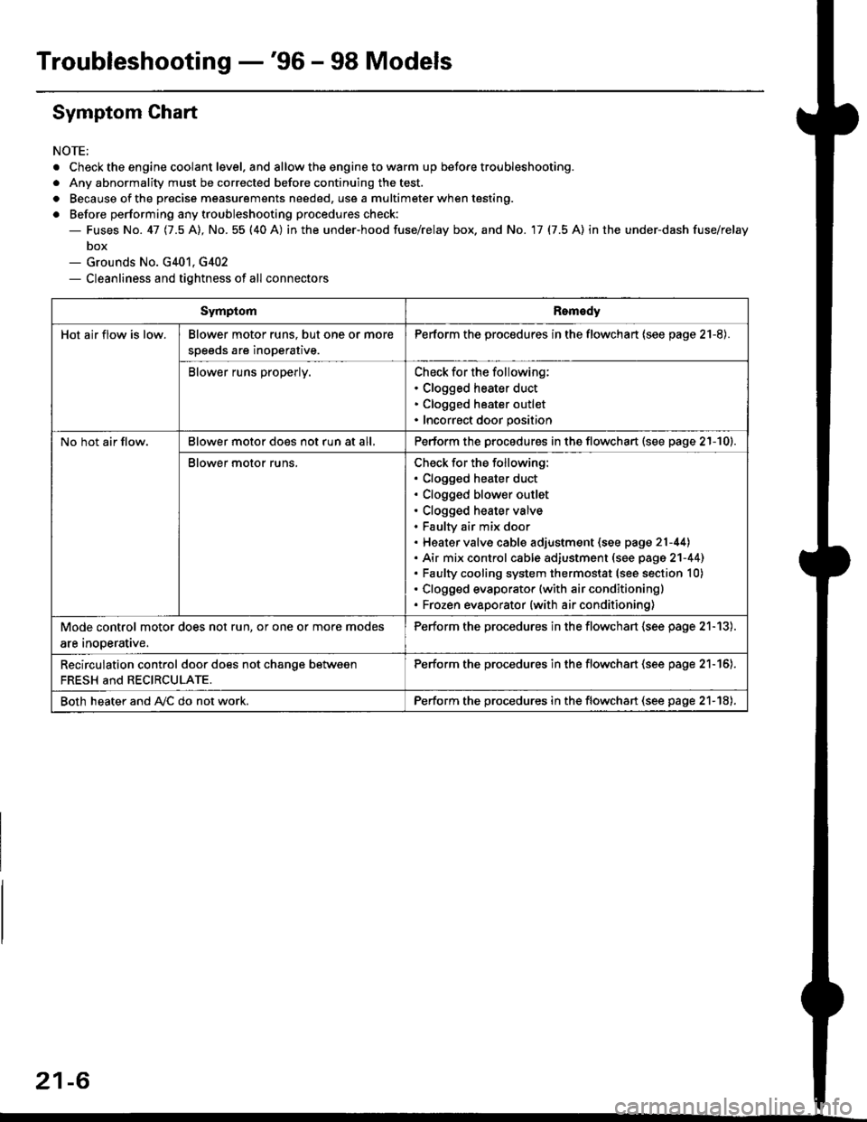
Symptom Chart
NOTE;
. Check the engine coolant level. and allow the engine to warm up before troubleshooting.
. Any abnormality must be corrected before continuing the test.
. Because of the precise measurements needed. use a multimeter when testing.
o Before performing any troubleshooting procedures check:- Fuses No. 41 11.5 Al, No. 55 (40 A) in the under-hood fuse/relay box. and No. 17 (7.5 A) in the under-dash fuse/relay
box- Grounds No. G401, G402- Cleanliness and tightness of all connectors
SymptomRomedy
Hot air flow is low.Blower motor runs. but one or more
speeds are inoperative.
Perform the procedures in the flowchart (see page 21-8).
Blower runs properly.Check for the following:. Clogged heater duct. Clogged heater outlet. Incorrect door position
No hot air flow.Blower motor does not run at all,Perform the procedures in the flowchart (see page 21-10).
Blower motor runs.Check for the following:. Clogged heater duct. Clogged blower outlet. Clogged heater valve. Faultv air mix door. Heater valve cable adjustment (see page 21-44). Air mix control cable adiustment (see page 2'l-441. Faulty cooling system thermostat (see section 10). Clogged evaporator (with air conditioning). Frozen evaporator {with air conditioning)
Mode control motor does not run, or one or more modes
are inooerative.
Perform the procedures in the flowchart (see page 21-13).
Recirculation control door does not chanqe between
FRESH and RECIRCULATE.
Perform the procedu.es in the flowchan (see page 21-16).
Both heater and A,/C do not work.Perform the procedures in the flowchart (see page 21-18),
21-6
Page 1384 of 2189
Troubleshooting -'96 - 98 Models
Blower Motor
BLOWER MOTOR 2P CONNECTOR
Wi.e side of fernale terminals
f=
l1l
r,l
ruumifalulau**'
I
Fl gr-urwnr
l1|_-_-l
t4 ,t
I
glower motor does not run at all.
Check the No.55 (40A)luse in theunder hood fuse/relay box, andthe No. 17 (7.5 A) luse in theundeFdash luse/relay box.
Repl.ce th. fuse{rl, .nd rochack.
Check the blower motor:1. Connect the No. 2 terminal ofthe blower motor 2P connoctor to body ground with a
lumper wrre.2. Turn the ignition switch ON (ll).
Does the blower motor run?
Chock for an opsn in the wire:1. Disconnect the ,umper wireand the blower motor 2P con-nector,2. Measure the voltage betweenthe No. 1 terminal and bodyground.
ls there battery voltage?
Ch6ck tha blower motor relay:1. Turn the ignition switch OFF.2. Remove the blower motorrelay from the under-hoodfuse/relay box, and test it (see
page 21-49).
Replace tha blower moior reley.
To page 21-11
fo page21'12
21-10
Page 1386 of 2189
Troubleshooting -'96 - 98 Models
From page 21-10
Check the under-hood fuse/relayDOX:N/leasure the voltage between theNo. 3 terminal of the blowermotor relay 4P socket and bodyground,
ls there baftery voltage?
Check lor an open in th€ wire:1. Turn the ignition switch ON (ll).
2. Measure the voltage betweenthe No. 4 terminal of the blow-er motor relay 4P socket andbody ground.
Repair open in tho wire betweenthe No. 17 fuss and tho blowelmotor rclay,
Check for en opon in the wire:1. Turn the ignition switch OFF.2. Check for continuity betweenthe No. 2 terminal of the blow-er motor relay 4P socket andbody ground.
Check foi an open in the wirebetwe€n the blower motor relavand body glound. lf the wiro isOK, check fo. poor ground atG{01 and G4O2.
ls there continuity?
Repair open in the BLU/WHTwire b€tween the blower motorrelav and the blower motor.
Blower Motor (cont'dl
BLOWER MOTOR RELAY 'P SOCKET
1211
tt-l_T
trv)
i
21-12
Page 1387 of 2189

Mode Control Motor
To page 21-14
MODE CONTROL MOTOR 7P CONNECTOR
'1
I2I57
BLK/YEL
Wire side of female terminals
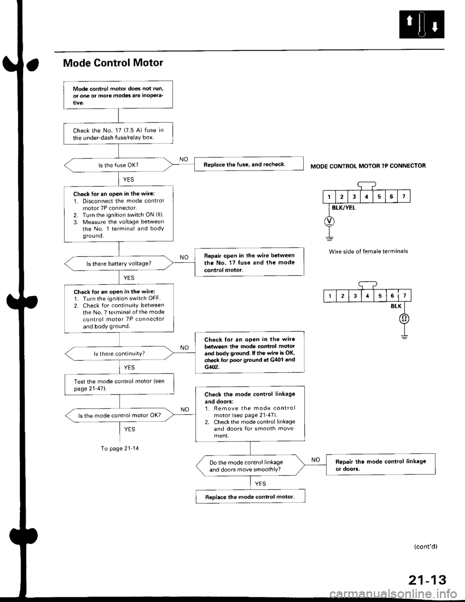
Mode control motor does not run,
or one of more modes are inoPela-
Check the No. '17 (7.5 A) fuse in
the under-dash fuse/relaY box.
Reolace the fuse, and recheck.
Check lor an open in the wire:
1. Disconnect the mode controlmotor 7P connector.2. Turn the ignition switch ON (ll).
3. Measure the voltage betweenthe No. l terminal and bodyg rou nd.
Repair open in the wire between
the No. 17 tuse and the mode
control motor.ls there batterY voltage?
Check {or an open in the wire:1. Turn the ignition switch OFF.
2. Check for continuity between
the No. 7 terminal of the mode
co nlrol motor 7P connector
and body ground.
Check for an open in the wire
batwe€n the mode contrcl motol
and body ground. lf the wir€ is OK,check for poor gtound at G/U)l and
G402.
ls there continuity?
Test the mode control motor (see
page21-471.Check the mod€ control linkage
and doors:1. Bemove the mode controlmotor (see page 21-47).2. Check the mode control linkageand doors for smooth move
ls the mode control motor OK?
Do the mode control linkageand doors move smoothlY?
Reolace the mode control motor,
I34561
BLK
[]
(cont'd)
Page 1390 of 2189

Troubleshooting -'96 - 98 Models
Recirculation Control Motor
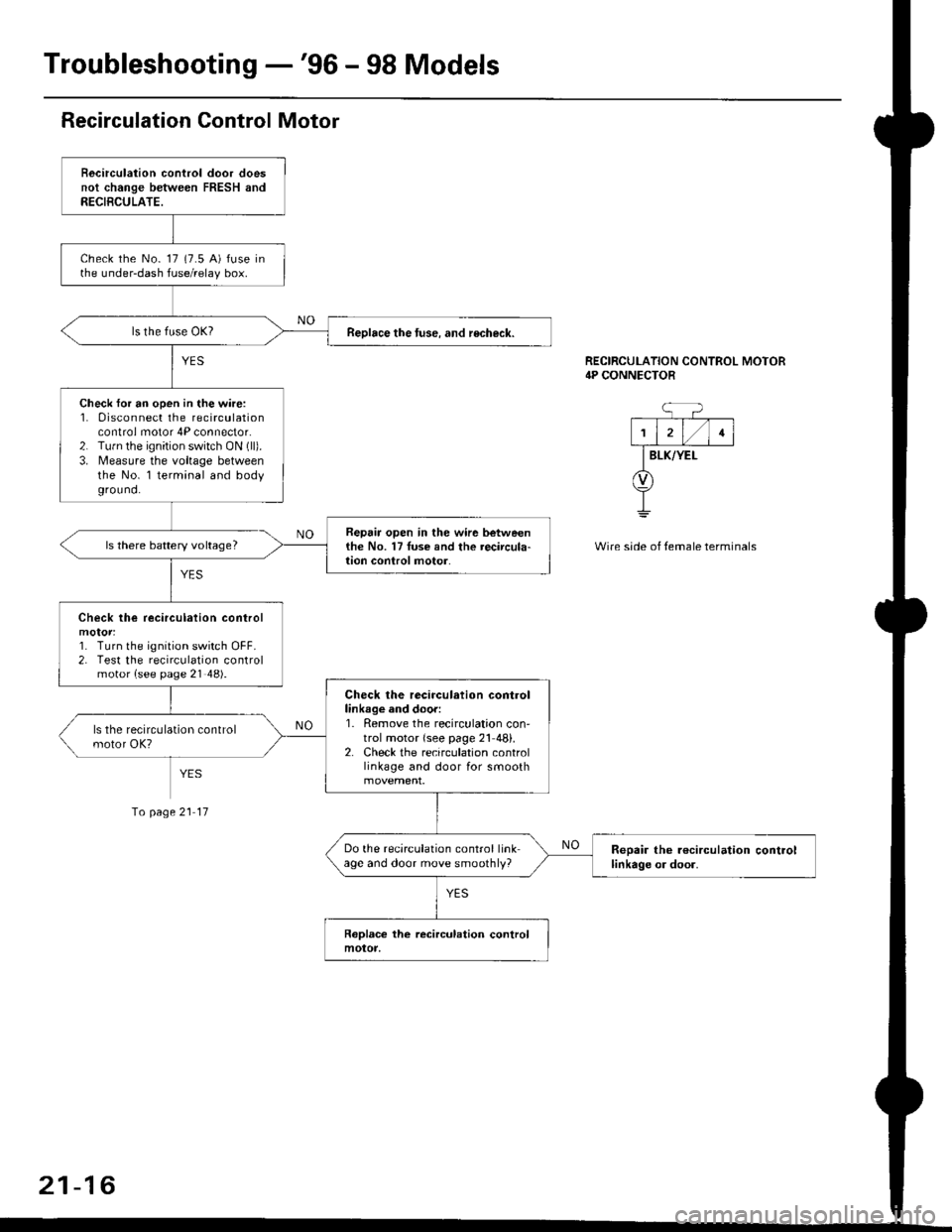
Becirculation control door doesnot change between FRESH andRECIBCULATE.
check the No- 17 (7.5 A) fuse inthe under-dash fuse/relay box.
Reolace the tuse. and recheck.
Check for an open in the wire:1. 0isconnect the recirculationcontrol motor 4P connector.2. Tu.n the ignition switch ON (ll).
3. Measure the voltage betweenthe No. l terminal and bodyground.
Repair open in the wir6 betweenthe No. 17Iuse and the recircula-lion conlrol motor.ls there battery voltage?
Check lhe recirculation control
1. Turn the ignition switch OFF.2. Test the recirculation controlmotor {see page 21 48).
Check the recirculation controllinkage and door:1. Remove the recirculation con'trol motor {see page 21 48}.2. Check the recirculation controllinkage and door for smooth
Do the recirculation control linkage and door move smoothly?Reoair the r€circulation controllinkage or door.
RECIRCULATION CONTROL MOTOR4P CONNECTOR
BLK/YEI-
Wire side of temale terminals
Io page 21 17
21-16