Page 189 of 2189

Cylinder HeadValve Guides
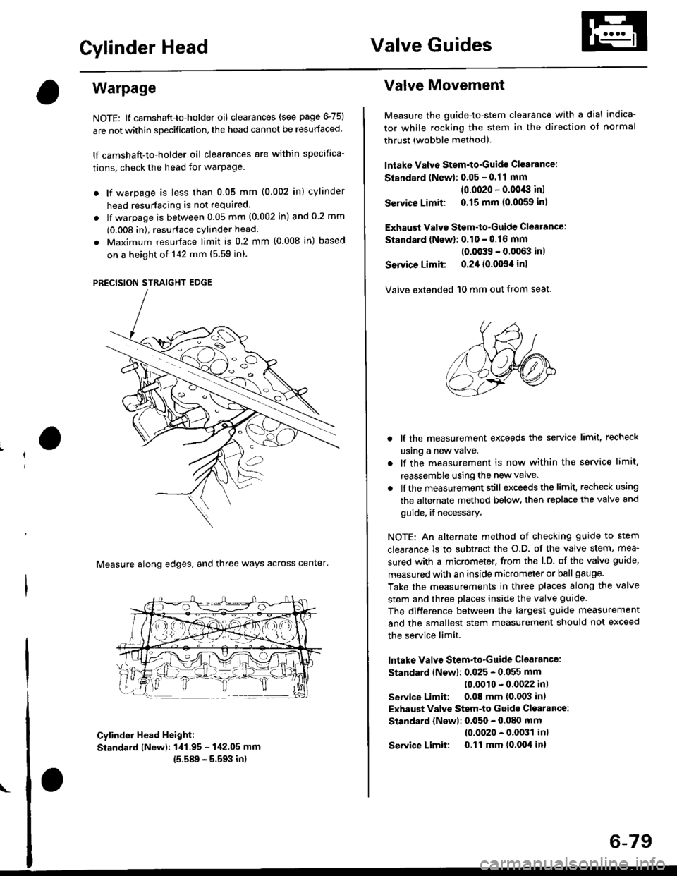
Warpage
NOTE: lf camshaft-to-holder oil clearances (see page 475)
are not within specification, the head cannot be resurfaced.
lf camshaft-to-holder oil clearances are within specifica-
tions, check the head for warPage.
. lf warpage is less than 0.05 mm (0.002 in) cylinder
head resurfacing is not required.
. lf warpage is between 0.05 mm (0.002 in) and 0 2 mm
(0.008 in), resurface cylinder head
. Maximum resurface limit is 0.2 mm (0.008 in) based
on a height of 142 mm (5.59 in).
PRECISION STRAIGHT EDGE
Measure along edges, and three ways across center'
Cylinder Head Height:
Standard lNewl: 1i11.95 - 142.05 mm
15.589 - 5.593 in)
Valve Movement
Measure the guide-to-stem clearance with a dial indica-
tor while rocking the stem in the direction of normal
thrust (wobble method).
lntake Valve Stem-to-Guide Cl6arance:
Standard (Newl: 0.05 - 0.11 mm
(0.0020 - 0.0043 inl
Service Limit: 0.15 mm {0.0059 inl
Exhaust Valve Stem-to-Guide Clealance:
Standard lNewl: 0.10 - 0.16 mm
(0.0039 - 0.0063 inl
Service Limit: 0.24 {0.0094 in)
Valve extended 10 mm out from seat.
lf the measurement exceeds the service limit, recheck
using a new valve.
lf the measurement is now within the service limit.
reassemble using the new valve
lf the measurement still exceeds the limit. recheck using
the alternate method below. then replace the valve and
guide, if necessary.
NOTE: An alternate method of checking guide to stem
clearance is to subtract the o.D. of the valve stem, mea-
sured with a micrometer, from the l.D. of the valve guide,
measured with an inside micrometer or ball gauge.
Take the measurements in three places along the valve
stem and three places inside the valve guide.
The difference between the largest guide measurement
and the smallest stem measurement should not exceed
the service limit.
lntake Valv€ Stem-to-Guide Clsarance:
Standard lNswl: 0.025 - 0.055 mm
10.0010 - 0.0022 inl
service Limit: 0.08 mm (0.003 in)
Exhaust Valve Stem-to Guide Cl€arance:
Standard {Newl: 0.050 - 0.080 mm
{0.0020 - 0.0031 inl
Service Limit 0.ll mm (0.004 in)
6-79
Page 190 of 2189

t
Valve Guides
Replacement
1. As illustrated below, use a commerciallv available
air-impact valve guide driver attachment modified
to fit the diameter of the valve guides. ln most
cases, the same procedure can be done using the
sDecial tool and a conventional hammer.
COMMERCIALLY AVAILABLEVALVE GUIDE DRIVER
87 mm -L- sz mm(3.43 inl I tz.zr int
rE-tt
10.8 mm10.42 inl
olVALVE GUIOE DRIVER,5.5 mm077,P - 0010100
Select the proper replacement guides and chill
them in the freezer section of a refrigerator for
about an hour.
Use a hot plate or oven to evenly heat the cylinder
head to 300"F (150"C). Monitor the temperature with
a cooking thermometer.
CAUTION:
. Do not use a torch; it may warp tho head.. Do not get tho head hotter than 300"F {150"C};excesgive heat may loosen thg valve seats.. To avoid burns. use haaw gloves whon handling
the heatod cylinder head.
6-80
Working from the camshaft side, use the driver and
an air hammer to drive the guide about 2 mm (0.1 in)
towards the combustion chamber. This will knock off
some ofthe carbon and make removaleasier.
CAUTION:
. Always wsar safety goggles or a face shield whsn
driving valve guides.
. Hold the air hammer dir€ctly in line with the
valve guide to prevont damaging thg dtiver.
Turn the head over and drive the guide out toward
the camshaft side of the head.
VALVE GUIOE DRIVER,5.5 mm077{2 - 0010100
lf a valve guide still won't move. drill it out with a8.0 mm (5/16 in) bit, then try again.
CAUTION: Drill guides only in extreme cases; you
could damago the cylinder head if ths guide br6aks.
Remove the new guide(s) from the freezer, one at a
time, as vou need them.
-:^-,65i^q
NNSp-<
Page 192 of 2189

Valves
1.
Installation
Coat the valve stems with oil. lnsert the valves into
the valve guides.
NOTE: Check that the valves move up and downsmoothly.
Installthe spring seats on the cylinder head.
Install the valve seals using the special tool.
NOTE: Exhaust and intake valve seals are not inter-
changeable.
WHITESPRING
VALVE GUIDE SEAL INSTALLERKD-28)g (Commercially available)NOTE: Use small lDend of tool,
2.
BRACKSPRING
VALVE SEALReplace.
tNsTALLERVALVE GUIDE SEALKD-2899NOTE: Use small lDend of tool
(
4. lnstall the valve spring and valve retainer, theninstall the valve spring compressor. Compress thespring, and install the valve keepers.
NOTE: Place the end of the valve spring with closely
wound coils toward the cylinder head.
VALVE SpRtNG VALVE SPRTNG
COMpRESSOR COMPRESSORATTACHMENT
ATTACHMENT EXTENSTON
0775? _ pJlOl0A o?MAF - PR9010A
VALVE SPRING COMPRESSORlCommercially available)Snap-on CF711 or KD-3tXlwith #32JAWSLightly tap the end of each valve stem two or threetimes with the wooden handle of a hammer to ensureproper seating of the valve and valve keepers.
NOTE: Tap the valve stem only along its axis soyou do not bend the stem.
I
5.
Page 193 of 2189
Rocker Arms
lnstallation
1.
2.
3.
lnstall the rocker arms in the reverse order of
removal:
. Valve adjusting locknuts should be loosened and
the adiusting screw, backed off before installa-
tron.
. The component parts must be reinstalled in the
original locations.
lnstall the lost motion assemblies.
lnstall the rocker arms while inserting the rocker
arm shaft into the cylinder head
NOTE: Remove the rubber band after installing the
rocker arms.
12 mm BOLT
\
6-83
4. Clean and install the rocker shaft orifices with new
O-rings. lf the holes in the rocker arm shaft and
cylinder head are not in line with each other, screw
a 12 mm bolt into the rocker arm shaft and rotate
the shaft.
NOTE: The shapes of the rocker shaft orifices tor
the intake and exhaust are different. The orific'
must be installed in the proper locations.
INTAKE ROCKER
SHAFT ORIFICE
EXHAUST ROCKER Clean
SHAFT ORIFICE
O.RING
O
Page 194 of 2189

I
Cylinder Head
Installation
lnstall the cylinder head in the reverse order of removal:
NOTE:
. Always use a new head and manifold gasket.. The cylinder head gasket is a metal gasket, Take carenot to bend it.
. Rotate the crankshaft, set the No. 1 piston at TDC (seepage 6-63).
. Do not use the middle cover and lower cover forstorang removed items.. Clean the middle cover and lower cover before instal_lation.
o Replace any washers that are damaged or deteriorated.
1. Install the cylinder head gasket, dowel pins and thehead oil control orifice on the cylinder head.
NOTE: Clean the oil control orifice when installing.
DOWEL PIN
6-84
2, Tighten the cylinder head bolts in two steps. In thefirst step, tighten all bolts in sequence to about 29N.m (3.0 kgf.m, 22 tbf.ftl. ln the final step, tighten inthe same sequence to 83 N.m (8.S kgf.m,6t lbf.ft).
NOTE:
. Apply clean engine oil to the bolt threads andunder the bolt head.. We recommend using a beam-type torquewrench. When using a preset-type torque wrench,be sure to tighten slowly and not to overtighten.. lf a bolt makes any noise while you are torquing it,loosen the bolt, and retighten it from the 1st step.
CYLINDER HEAD BOLT TOROUE SEOUENCE
11x 1.5 mm83 N.m 18.5 kgf.m, 61 tbf.ftl
Install the intake manifold and tighten the nuts in acflsscross pattern in two or three steps, beginningwith the inner nuts.. Always use a new intake manifold gasket.
Install the exhaust manifold and tighten the newself-locking nuts in a crisscross pattern in two orthree steps. beginning with the inner nuts.. Always use a new exhaust manifold gasket.
4.
Page 195 of 2189

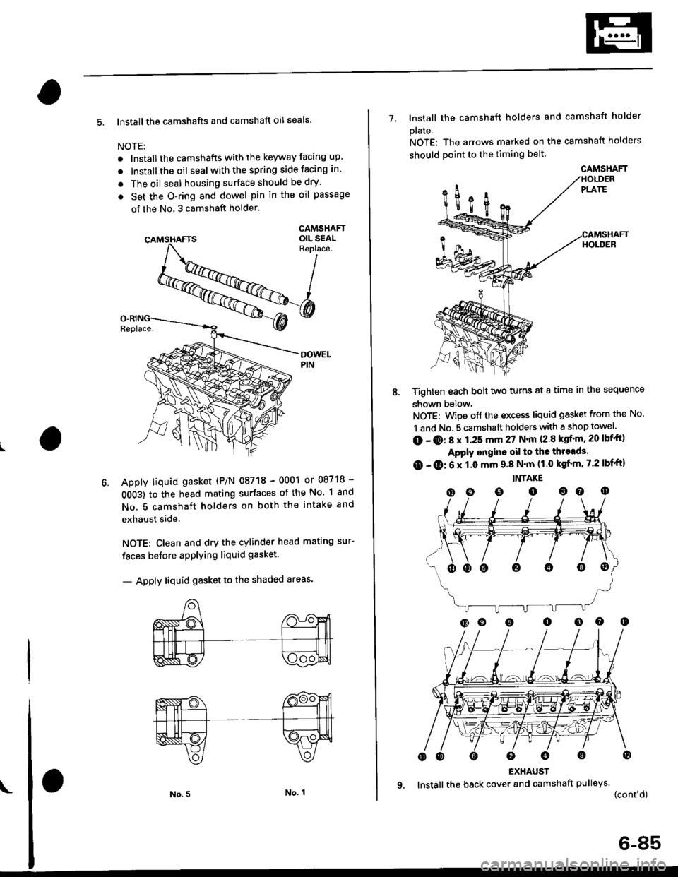
5. lnstall the camshafts and camshaft oil seals.
NOTE:
. lnstallthe camshafts with the keyway facing up.
. lnstall the oil seal withthespring side facing in.
. The oil seal housing surface should be dry'
. Set the O-ring and dowel pin in the oil passage
of the No, 3 camshaft holder'
CAMSHAFTOIL SEALReplace.
Apply liquid gasket (P/N 08718 - 0001 or 08718 -
0OO3) to the head mating surfaces of the No. 1 and
No. 5 camshaft holders on both the intake and
exhaust side.
NOTE: Clean and dry the cylinder head mating sur-
faces before applying liquid gasket.
- Apply liquid gasket to the shaded areas'
7- lnstall the camshaft holders and camshaft holder
plaIe.
NOTE: The arrows marked on the camshaft holders
should point to the timing belt.
Tighten each bolt two turns at a time in the sequence
shown below.
NOTE: Wipe off the excess liquid gasket from the No.
1 and No. 5 camshaft holders with a shop towel
(D - @: 8 x 1.25 mm 27 N.|n (2.8 ksf'm, 20 lbf'ft)
Apply ongine oil to the throads.
O - O: 6 x 1.0 mm 9.8 N'm (1.0 kgfrm, 7.2 lbf'ft)
INTAKE
(D o o o oo o
EXHAUST
lnstall the back cover and camshaft pulleys.
{cont'd)
oooo0o@
CAMSHAFT
6-85
Page 196 of 2189

Cylinder Head
Installation (cont'dl
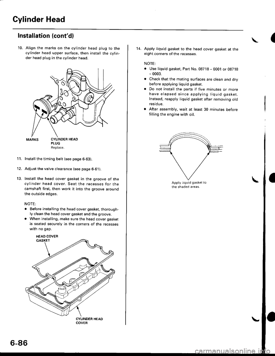
10. Align the marks on the cylinder head plug to thecylinder head upper surface, then install the cylin,
der head plug in the cylinder head.
PLUGReplace.
Install the timing belt (see page 6-63).
Adjust the valve clearance (see page 6-61).
Install the head cover gasket in the groove of the
cylinder head cover. Seat the recesses for the
camshaft first, then work it into the groove around
the outside edges,
NOTE:
. Before installing the head cover gasket, thorough-ly clean the head cover gasket and the groove.
. When installing, make sure the head cover gasket
is seated securely in the corners of the recesses
wrrn no gap.
11.
13.
1'
CYLINDEB HEAD
HEAD COVEB
6-86
(\
14. Apply liquid gasket to the head cover gasket at theeight corners of the recesses.
NOTE:
. Use liquid gasket, Part No. 08718 - 0001 or 08718- 0003.
. Check that the mating surfaces are clean and drybefore applying liquid gasket
. Do not install the parts if five minutes or morehave elapsed since applying tiquid gasket.
Instead, reapply liquid gasket after removing oldrestdue.
. After assembly. wait at least 30 minutes before
filling the engine with oil.
Page 197 of 2189
15. When installing the cylinder head cover, hold the
head cover gasket in the groove by placing your fin-
gers on the camshaft holder contacting surfaces
(toD of the semicircles).
Once the cylinder head cover is on the cylinder
head, slide the cover slightly back and forth to seat
the head cover gasket.
NOTE:
. Be{ore installing the cylinder head cover, clean
the cvlinder head contacting surfaces using a
shoP towel.
. Oo not touch the parts where liquid gasket was
applied.
. Replace any washer taht is damaged or deter'o-
rated.
t
\
6-A7
16. Tighten the nuts in two or three steps. In the final
step, tighten all nuts, in sequence, to 9 8 N'm {1 0
kgf.m, 7.2 lbf.ft).
NOTE: After assembly, wait at least 30 minutes
before filling the engine with oil.
After installing, check that all tubes' hoses and con-
nectors are installed correctly.17.