1999 HONDA CIVIC wire
[x] Cancel search: wirePage 1775 of 2189
)
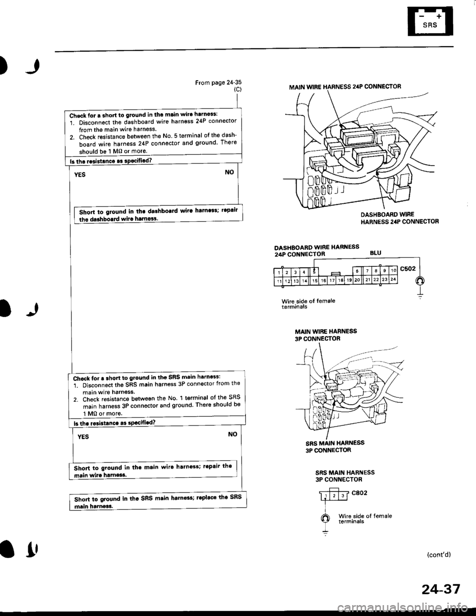
From page 24-35(c)
DASHEOARD WIRE HARNESS24P CONNECTOR
DASHBOARD WIREHARNESS 24P CONNECTOR
BLU
l)
Wke side oI femaleterminals
MAIN WIBE HARNESS3P CONNECTOR
3P CONNECTOR
SRS MAIN HARNESS3P CONNECTOR
(cont'd)
MAIN WIRE HARNESS 24P CONNECTOR
Check lor a 3hort to glound in tho main wira harno$:
1. Disconnect the dashboard wire harness 24P connector
from the main wire harness.
2, Check resistance between the No 5 terminal ofthedash-
board wire harness 24P connector snd ground There
should be 1 M0 or more
Short to giound in tha dalhbo!]d wir! ha]n'$; t'plil
lho darhborrd wira hrrnos!.
Chock for ! shon to ground in tho SRS main herness:
1. Disconnect the SRS main harness 3P connector from the
main wire harness.2. Check resistanco botween the No. 1 terminal of the SRS
main harness 3P connector and ground, There shor,lld be
Short to ground in tha main wir6 hainoss; r'Prir the
Short to ground in thc SRS main harn6s; leplac' th' SRS
l1'
24-37
Page 1776 of 2189
Troubleshooting
The SRS Indicator Light Doesn't Go Off -'98 - 00 Models (cont'dl
From page 24 36(D)
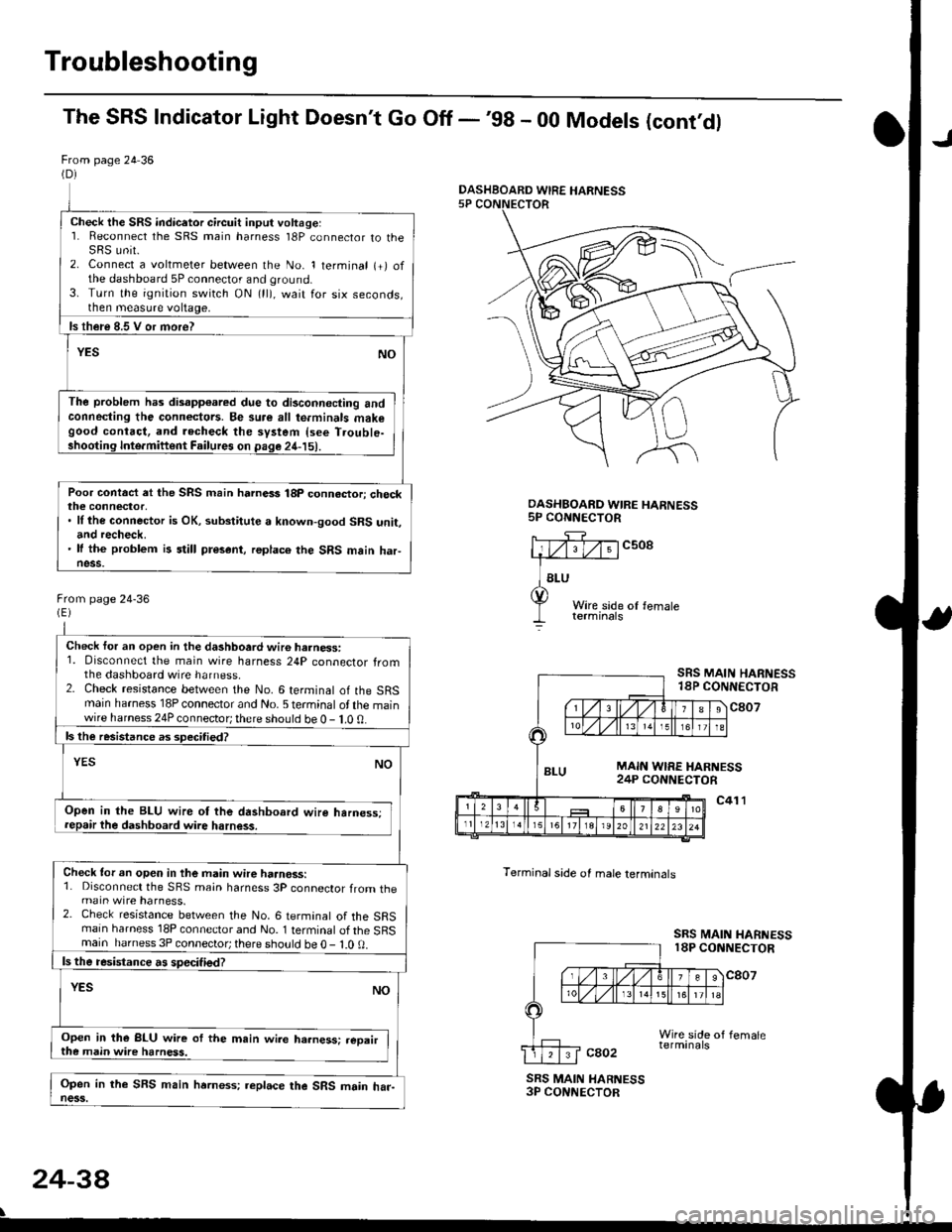
Check the SRS indicetor circuit input voltage:1. Reconnect the SRS main harness l8P connector to theSRS unit.2. Connect a voltmeter between the No. 1 terminal (+) ofthe dashboard 5P connector and ground.3. Turn the ignition switch ON (ll), wait for six seconds,then measure voltage,
ls th€re 8.5 V or more?
YESNO
The problem has disapp€ared due to di3connecting andconneding the connectors. Be su.e all te.minals makegood contact, and recheck the system {see T.ouble-shooting Inte.miftent Failures on page 24-15).
Poor contact et the SRS main harnass 18p connactori checkthe connector,. ll the connector is OK, substitute a known-good SRS unit,and recheck.' It the problem is still present, replace the SRS main haFness.
From page 24-36
Check for an open in the dashboard wir6 harness:1. Disconnect the main wire harness 24P connector fromthe dashboard wire harness.2. Check resistance between the No. 6 terminal of the SRSmain harness 18P connector and No. 5 terminal of the mainwire harness 24P connector; there should be 0 - 1.0 0.
ls the resistance as 3pecitied?
YESNO
Open in the BLU wire ot the dashboard wire harness;repair the dashboard wire harness.
Check tor an open in the main wire haanoss:1. Disconnect the SRS main harness 3P connector from themain wire harness.2. Check resistance between the No. 6 termanal of the SRSmain harness 18P connector and No. 1 terminal of the SRSmain harness 3P connector; there sho!ld be O - l.O 0.
ls the resistance a! specified?
YESNO
Open in the BLU wire of the m.in wire ha.ness: .eoairthe main wire harness.
Open in the SFS main hrrness; replace the SRS main har-ness.
DASHBOARD WIRE HARNESS5P CONNECTOR
c508
Terminal side of male lerminals
SRS MAIN HARNESS18P CONNECTOR
c807
c41 l
SRS MAIN HARNESS18P CONNECTOR
cao2
SRS MAIN HARNESS3P CONNECTOR
24-38
\
DASHBOARD WIRE HARNESS
Page 1779 of 2189
)
From page 24-40
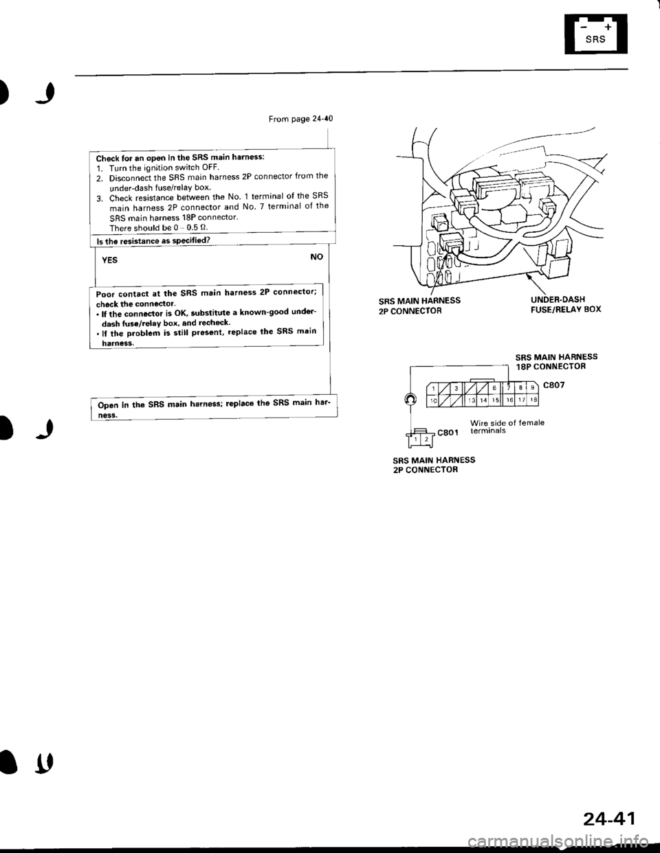
Check for an open in the SRS main harn6s:
1. Turn the ignition switch OFF.
2. Disconnect the SRS main harness 2P connector from the
under-dash fuse/relay box
3. Check resistance between the No. 1 terminal ol the SRS
main harness 2P connector and No. 7 terminal of the
SRS main harness 18P connector.
Thereshouldbe0 05O
ls the resistance es specitied?
YES
Poor contact at the SRS main hatness 2P connector;
check the connector-. It the connector i3 OK, substitute a known-good und€r-
dash fuse/relav box, and recheck..ll the Droblem i5 still pres€nt, replace lhe SRS main
harness.
NO
Open in the SRS main hsrness; leplaco the SRS main har-
ness.
)
FUSE/RELAY BOX
SRS MAIN HARNESS18P CONNECTOR
c807
Wire side of femaleterminals
SRS MAIN HARNESS2P CONNECTOR
24-41
lrt
Page 1782 of 2189
Troubleshooting
DTC 1-3
CAUTION: Whenever the ignition switch is ON {lll, orhas been turned OFF lor less than thrEe minutes, becaroful not to bump the SRS unit; the airbag(s) couldaccidenlally deploy and cause damage 01 iniuries.
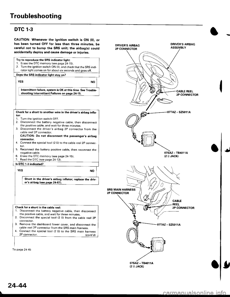
DRIVER'S AIRBAGASSEMALY
REEL2P CONNECTOR
AZ - SZ5011A
07saz - TB4011A{2 0 JACK)
CABLEREEL2P CONNECTOR
07TAZ - SZ5011A
TrV to reproduce the SRS indicator light:1. Erase the DTC memory (see page 24-15).2. Turn the ignition switch ON (ll), and check that the SRS indicator light comes on for about six seconds and goes off.
Does the SRS indicalor light stav on?
YESNO
Intermittent lailure. system is OK ai this tim€. Se€ Troubl€-shooting Intermittent Failures on page 24-15.
Check tor a short lo another wire in the drivo.'s eirbrg in{la-
1. Turn the ignition switch OFF.2. Disconnect the battery negative cable, then disconnectthe positive cable, and wait for three minutes.3. Disconnect the driver's airbag 2P connector from thecable reel 2P connector,CAUTION: Do not disconnect the passenger's airb.gconnector,4. Connect the special tool (2 0)to the cable reel 2P connector,5. Reconnect the baftery positive cable, then reconnect thenegative cable,6. Erase the DTC memory (see page 24 15).7. Read the DTC (see page 24-13).
ls DTC 1-3 indicated?
NOYES
Shon in the driver's airbag intlator; replace the driv-er's airbag {see page 24-67}.
Check lor a short in the ceble reel:1. Disconnect the battery negative cable, then disconnectthe positive cable, and wait for three minutes.2. Disconnect the special tool (2 O) from the cable reel 2p
3. Remove the dashboard lower cover, and disconnect thecable reel 2P connector from the SRS marn naroess.4. Connect the special tool (2 O) to the SRS main harness2P coonector. {cont,di
fo page24-45
SRS MAIN HARNESS
24-44
07sAz - TBr011At2 0 JACKI
Page 1790 of 2189
Troubleshooting
DTC 2-3 - With Front Passenger's Airbag
CAUTIONT Whanever ihe ignhion switch is ON lll), or
has been turnod OFF lor le33 than threo minutes. be
careful not to bump lhe SRS unit; ths airbags could
accidontally deploy lnd cause damage or inluries.
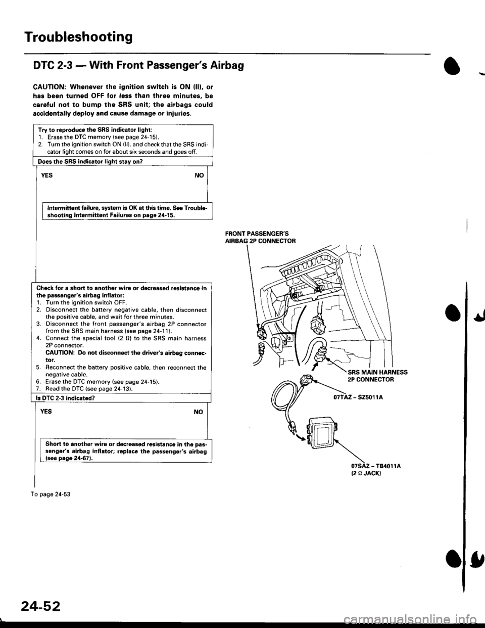
FRONT PASSENGER'SAIRBAG 2P CONNECTOR
- szsor la
{2 0 JACK)
Try to reproduce tho SRS indicator light:1. Erase the DTC memory (see page 24 15).2. Turn the ignition switch ON 1ll), and check that the SRS indi,cator light comes on for about six seconds and goes off.
Doe3 the SnS indicator light 3t.y on?
NOYES
Intermittort tailura, 3y3tem b OK at this time. S€e Trouble-shooting Intormittent Failuros on page 24-15.
Check tor a 3hort io another wire or dec.oasod relirtanct inth6 passonger's airbag inflato.:1. Turn the ignition switch OFF.2. Disconnect the battery negative cable, then disconnectthe Dositive cable, and wait for three minutes.3. Disconnect the tront passenger's airbag 2P connectorfrom the SFS main harness (see page 24-11).4. Connect the special tool (2 O) to the SRS main harness2P connector.CAUTION: Do not disconn€ct th6 driver's airbag connec-tor.5. Reconnect the baftery positive cable, then .econnect thonegative cable.6. Erase the DTC memory {see page 24-15).7. Read the DTC (see page 24 13).
l. DTC 2.3 indicated?
YESNO
Short io another wiao or d€creased rcsi3tanc6 in the prs-3enger's airbag intlator; repl.ce the passong.r's .irbaglsee page 2467).
To page 24-53
24-52
Page 1808 of 2189
Airbag
Disposal
Before scrapping any airbags (including those in a wholevehicle to be scrapped), the airbags must be deployed. lfthe vehicle is still within the warranty period, before youdeploy the airbags, the Honda District Service Managermust give approval and/or special instructions. Onlv afterthe airbags have been deployed (as the result of vehiclecollision, for example), can they be scrapped.lf the airbags appear intact (not deployed). treat themwith extreme caution.
Follow this p.ocedure:
Deploying the Airbags: In.vehiclo
NOTE: lf an SRS vehicle is to be entirely scrapped, itsairbags should be deployed while still in the vehicle. Theairbags should not be considered as salvageable partsand should never be installed in another veh;cle.
!@ confirm thst oach airbag assembty issecurely mounted; otharwiso. sev€re personal iniurycould result lrom deployment.
1. Disconnect the baftery negative cable, then discon_nect the positive cable.
2. Confirm that the special tool is functioning properlyby following the check procedure on the tool labelor on page 24-'l'l .
Driver's Airbag:
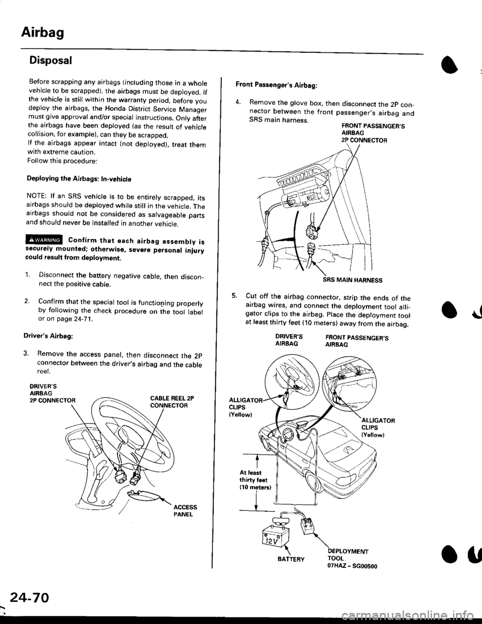
3. Remove the access panel, then disconnect the 2pconnector between the driver,s airbag and the cablereet.
DRIVER'SAIRBAG2P CONNECTOR
24-70
BATTERY.U
Front Passenger's Airbag:
4. Remove the glove box, then disconnect the 2p con-nector between the lront passenger,s airbag andSRS main harness.FRONT PASSENGER'SAIREAG2P CONNECTOB
SRS MAIN HARNESS
Cut off the airbag connector, strip the ends of theairbag wires, and connect the deployment tool alli_gator clips to the airbag. place the deployment toolat least thirty feet (10 meters) away from the airbag.
a!
DRIVER'SAIRBAGFRONT PASSENGER'SAIRBAG
ALLIGACLIPS(Yellow)ALLIGATORCLIPS{Yellowl
At loastthiny toet(10 metorsl
Page 1809 of 2189
E-
)I
Connect a 12 volt battery to the tool:
. lf the green light on the tool comes on, the aar-
bag igniter circuit is defective and cannot deploy
the airbag. Go to Damaged Airbag Special
Procedure.
. lf the red light on the tool comes on, the airbag is
ready to be deployed.
Push the tool's deployment switch. The airbag
should deploY (deployment is both highly audible
and visible; a loud noise and rapid inflation of the
bag, followed by slow deflation).
. lf the airbags deploy and the green light on the
tool comes on. continue with this procedure.
. l{ an airbag doesn't deploy, yet the green light
comes ON, its igniter is defective. Go to Dam-
aged Airbag Special Procedure.
!!@ During doployment, the airbag sssom'
bly can become hot enough to buln you. Wait thir'
ty minutes aftsr deployment belore touching tho
assembly.
Dispose of the complete airbag assembly. No part
of it can be reused. Place it in a sturdy plastic bag,
and seal it securelY,
CAUTION:
. Wear a fsce shield and gloves when handling a
deployed airbag.
. Wash your hands and rinse them well with
wat6r after handling. deployed airbag.
t('
24-71
7.
AIRAAG
Doploying th6 Airbag: Out-of-vehicle
NOTE: lf an intact airbag has been removed from a
scrapped vehicle. or has been found defective or dam-
aged during transit, storage or service, it should be
deployed as follows:
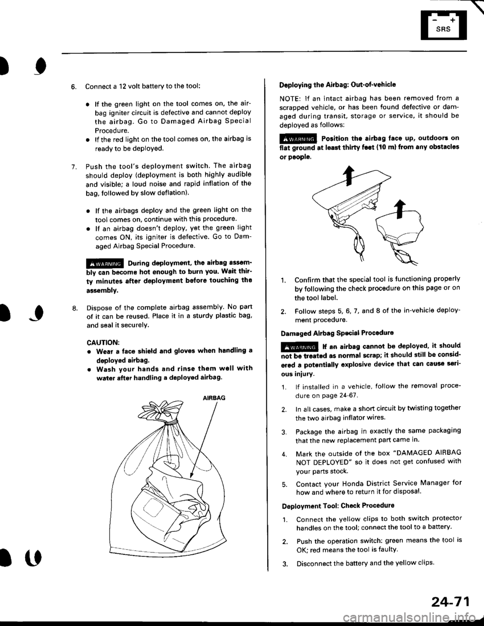
@ Po3ition the airbag laca up, outdoors on
flat ground at lsast thirty f€€t (t0 ml from any obstacles
or people.
1. Confirm that the special tool is tunctioning properly
by following the check procedure on this page or on
the tool label.
2. Follow steps 5, 6, 7, and I of the in-vehicle deploy-
menl Drocequre.
Damaged Airbag Spacial Procedure
!@ r an airb.g cannot be deployed, it should
iiiTi-treatcd as normal scrap; il should still be consid-
srsd a potontially oxplosive device that can cau3o ssti-
ous iniury.
1. lf installed in a vehicle, lollow the removal proce-
dure on page 24-67.
2. In all cases. make a short circuit by twisting together
the two airbag inflator wires.
3. Package the airbag in exactly the same packaging
that the new replacement part came in.
4. Mark the outside of the box "DAMAGED AIRBAG
NOT DEPLOYED" so it does not get confused with
your Parts stock.
5. Contact your Honda District Service Manager for
how and where to return it for disposal.
Deployment Tool: Check Procedur€
1. Connect the yellow clips to both switch protector
handles on the tool; connect the tool to a battery.
2. Push the operation switch: green means the tool is
OK: red means the tool is faulty
3. Disconnect the battery and the yellow clips.
Page 1811 of 2189
\
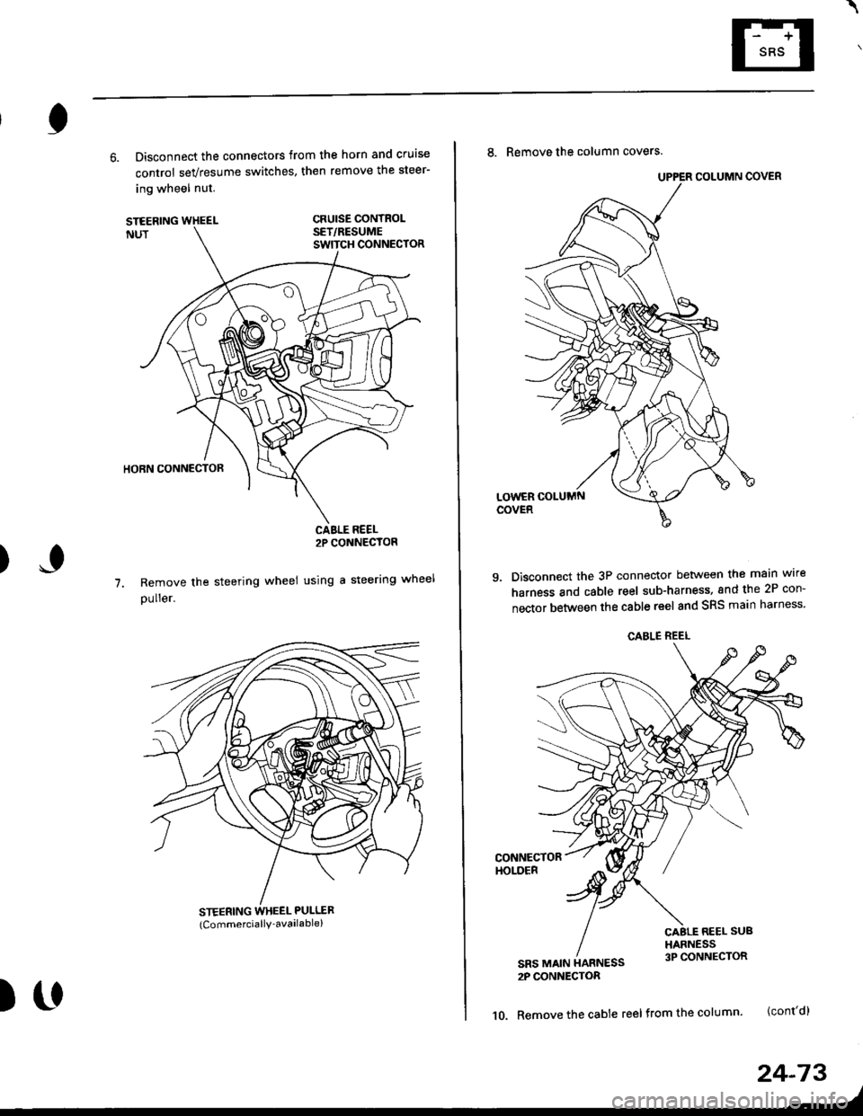
6. Disconnect the connectors from the horn and cruise
control sevresume switches, then remove the steer-
ing wheel nut.
STEERINGNUT
CRUISE CONTROLSET/RESUMESWITCH CONNECTOR
)
HORN CONNECTOR
Remove the steerlng
pulrer.
CABLE REEL2P CONNECYOR
wheel using a steering wheel7.
STEERING WHEEL PULLEF
{Commerciallv_available)
)U
8. Remove the column covers.
Disconnect the 3P connector between the main wire
harness and cable reel sub-harness, 8nd the 2P con-
nector between the cable reel and SRS main harness'
CONNECTORHOLOER
SRS MAIN HARNESS2P CONNECTON
CABLE REEL SUBHARNESS3P CONNECTOR
10. Remove the cable reel from the column {cont'd}
24,73
--/
CABLE REEL