Page 1565 of 2189
-Starter Test
NOTE; The air temoerature must be between 59 and
100'F (15 and 38"C) before testing.
Recommended Procedure:
. Use a staner system tester.
. Connect and operate the equipment in accordance
with the manufacturer's instructions.
. Test and troubleshoot as described,
Alternate Procedurg:
. Use the following equipment:- Ammeter, 0 - 400 A
- Voltmeter, 0 - 20 V (accurate within 0.1 volt)
- Tachometer, 0 - 1,200 rpm
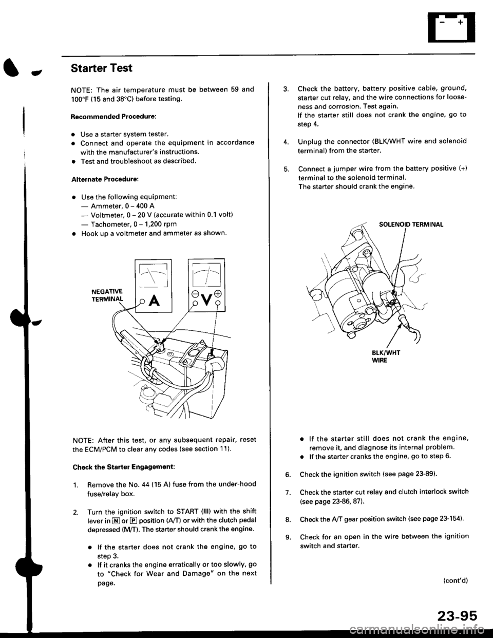
. Hook up a voltmeter and ammeter as shown.
NEGATIVETERMINAL
NOTE: After this test, or any subsequent repair. reset
the ECM/PCM to clear any codes (see section l1)
Check the Start€r Engagemont:
1. Remove the No. 44 (15 A) fuse from the under-hood
fuse/relay box,
2. Turn the ignition switch to START (llll with the shift
lever in E or E position (rVT) or with the clutch pedal
depressed {M/T). The starter should crank the engine.
. lf the starter does not crank the engine, go to
step 3.
. lf itcranksthe engineerraticallyortooslowly, go
to "Check for Wear and Damage" on the next
page.
Check the battery. battery positive cable, ground,
starter cut relay, and the wire connections for loose-
ness and corrosion, Test again.
lf the starter still does not crank the engine, go to
step 4,
Unplug the connector (BLK,/WHT wire and solenoid
terminal) from the starter,
Connect a jumper wire from the battery positive (+)
terminal to the solenoid terminal.
The starter should crank the engine.
. lf the starter still does not crank the engine,
remove it, and diagnose its internal problem
. lf the startercranksthe engine, goto step 6.
Check the ignition switch (see page 23-891.
Check the starter cut relay and clutch interlock switch
(see page 23-86,87).
Check the A/f gear position switch (see page 23-154).
Check for an open in the wire between the ignition
switch and starter.
7.
(cont'd)
23-95
9.
Page 1570 of 2189
Starting System
Starter Replacement
1.Make sure you have the anti-theft code for the
radio, then write down the frequencies for the
radio's preset buttons ('99 - 00 models).
Disconnect the battery negative cable.
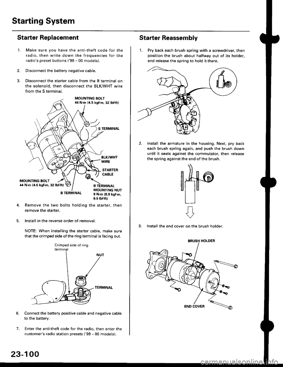
Disconnect the starter cable from the B terminal on
the solenoid, then disconnect the BLK trHT wire
from the S terminal.
MOUNTING BOLT44 N.m l/t.s kgf.m. 32 lbf.ft)
S TERMINAL
MOUNTING BOLT6,1 N.m {4.5 kstm.32lbtftl
MOUNTING NUT9 N,m {0.9 kgl.m,6.s lbtftl
B TERMINAL
4. Remove the two bolts holding the starter, then
remove the starter.
lnstall in the reverse order of removal.
NOTE: When installing the staner cable, make sure
that the crimped side ofthe ring terminal is facing out.
TERMINAL
Connect the battery positive cable and negative cable
to the battery.
Enter the anti-theft code for the radio, then enter the
customer's radio station presets ('99 - 00 models).
7.
Crimped side of ring
23-100
Starter Reassembly
'1. Pry back each brush spring with a screwdriver, then
position the brush about halfway out of its holder.
and release the spring to hold it there.
Install the armature in the housing. Next, pry back
each brush spring again, and push the brush down
until it seats against the commutator, then release
the spring against the end of the brush.
aw
3. Install the end cover on the brush holder.
ERUSH HOLDER
Page 1571 of 2189
-Performance Test
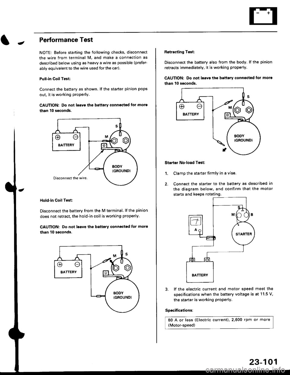
NOTE: Before staning the following checks. disconnect
the wire from terminal M. and make a connection as
described below using as heavy a wire as possible (prefer-
ably equivalent to the wire used for the car).
Pull-in CoilTest:
Connect the battery as shown, lf the staner pinion pops
out. it is working proPerly.
CAUTION: Do not leavo tho batterv connost€d for more
than 10 seconds.
Hold-in Coil Test:
Disconnect the battery from the M terminal' lf the pinion
does not retract, the hold-in coil is working properly.
CAUTION: Do not loavc lhe battsry connected for mot6
than 10 ssconds.
Retracting Tosi:
Disconnect the battery also from the body. lf the pinion
retracts immediately, it is working properly.
GAUTION: Do not loave the baftery conn€ctod tor more
than 10 seconds.
Startor No-load Tost:
Clamp the starter firmly in a vise.
Connect the starter to the battery as described in
the diagram below, and confirm that the motor
starts and keeps rotating.
1.
3, lf the electric current and motor speed
specifications when the battery voltage is
the starter is working ProPerly.
Specifications:
80 A or less (Electric current),2,600 rpm or more
(Motor-speed)
meet the
at 11.5 V,
23-101
Page 1572 of 2189
lgnition System
Component Location Index
IGNITION TIMING CONTROL SYSTEM
. Troubleshooting, section 11
. ldle speed Inspection/Adjustment. section 11
. Inspection and Setting, page 23-105
SERVICE CHECK CONNECTOR {2P}Iwiie colors: 8RN and BLKI
TEST TACI{OMETER CONNECTOB
IGNITION WIRESlnspection and Test, page 23-110
PLUGSInspection, page 23 1 11
Replacement, page 23'106Overhaul, page 23-107lgnition Coil Test, page 23'110lgnition Control Module llCM)Input Test, page 23-109
23-102
Page 1575 of 2189
-lgnition Timing Inspection and Setting
1.Check the idle speed, and adjust it it necessary (see
section 'l '1 ).
Pull out the service check connector 2P (BRN and BLK
wires) from the connector holder located under the
dash on the front passenger side, then connect the
SCS service connector (T/N 07PAZ - 0010'100) to it.
Start the engine. Hold the engine at 3.000 rpm with
no load {A,/T in E or E. M/T in neutral) until the
radiator fan comes on, then let it idle.
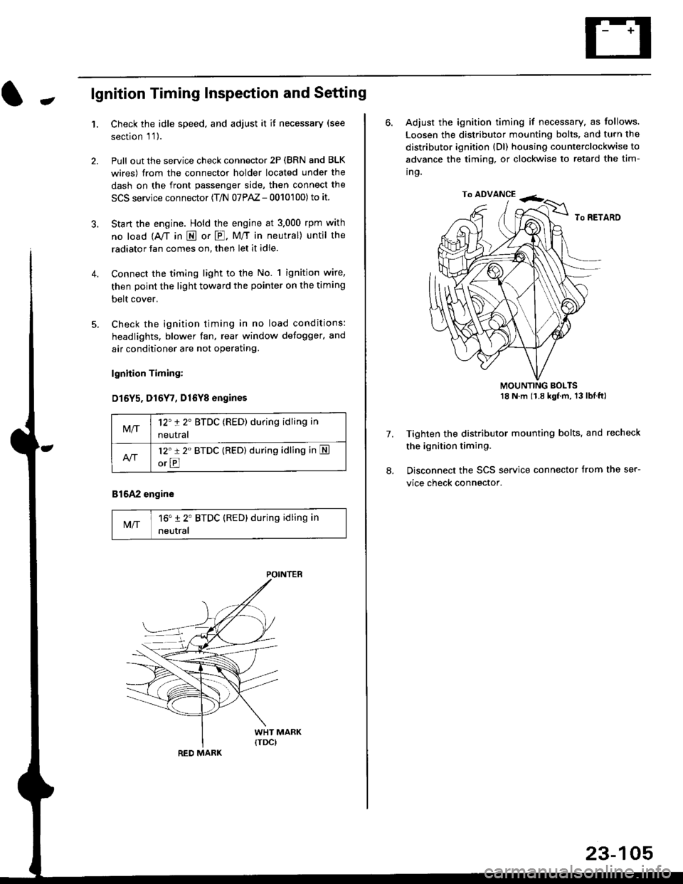
Connect the timing light to the No. 1 ignition wire,
then point the light toward the pointer on the timing
belt cover.
Check the ignition timing in no load conditions:
headlights. blower fan, rear window defogger, and
air conditioner are not operating.
lgnhion Timing:
D15Y5. D16Y7, Dl6Yg engines
816A2 engine
MIT16" 12' BTDC (RED) during idling in
neutral
M/T12't 2" BTDC (RED) during idling in
neutral
l2'r 2" BTDC {RED) during idling in S
orE
POINTEB
RED MARK
23-105
ro ADVANCE -<;,
6. Adjust the ignition timing if necessary, as follows.
Loosen the distributor mounting bolts. and turn the
distributor ignition (Dl) housing counterclockwise to
advance the timing, or clockwise to retard the tim-
ing.
MOUNTING BOLTS18 N'm (1.8 kgfm, 13lblftl
Tighten the distributor mounting bolts, and recheck
the ignition timing.
Disconnect the SCS service connector from the ser-
vice check connector.
7.
Page 1576 of 2189
lgnition System
Distributor Replacement
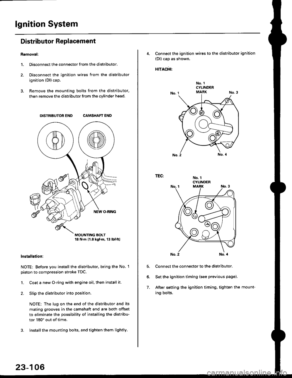
Removal:
1. Disconnect the connector from the distributor.
2. Disconnect the ignition wires from the distributor
ignition {Dl) cap.
3. Remove the mounting bolts from the distributor,
then remove the distributor from the cylinder head.
DISTRIBUTOR END CAMSHAFT END
MOUNTING BOLT18 N.m 11.8 kgtm, 13lbf.ltl
lnstallation:
NOTE: Before you install the distributor. bring the No. 1
piston to compression stroke TDC.
1. Coat a new O-ring with engine oil, then install it.
2. Slip the distributor into position
NOTE: The lug on the end of the distributor and its
mating grooves in the camshaft end are both offset
to eliminate the possibility of installing the distribu-
tor 180" out of time.
3. Installthe mounting bolts, and tighten them lightly.
23-106
4, Connect the ignition wires to the distributor ignition
(Dl) cap as shown.
rracfit'
No. 1CYLINDERMARK
No. 1CYLINDER
TEG:
5.
6.
7.
No. 2No. a
Connect the connector to the distributor.
Set the ignition timing (see previous page).
After setting the ignition timing, tighten the mount-
ing bolts.
Page 1579 of 2189
Jlgnition Control Module (lCMl Input Test
NOTE:
. See section 1'l when the malfunction indicator lamp
(MlL) turned on.
. Perform an input test for the ignition control module
(lCM) after finishing the fundamental tests for the
ignition system and the fuel and emissions systems
1. Remove the distributor ignition (Dl) cap, the distrib-
utor ignition (Dl) rotor and the leak cover (TEC).
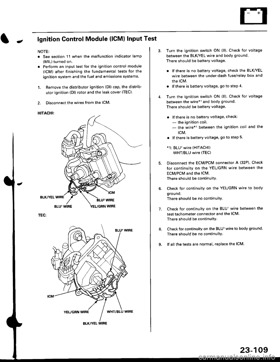
2. Disconnect the wires from the lCM.
HITACHI:
BLK/YEL
TEC:
Turn the ignition switch ON (ll). Check for voltage
between the BLK/YEL wire and body ground.
There should be battery voltage.
. lf there is no battery voltage, check the BLK/YEL
wire between the under-dash fuse/relay box and
rhe lcM.
. lf there is battery voltage, go to step 4.
Turn the ignition switch ON (ll). Check for voltage
between the wire*r and body ground
There should be battery voltage.
. lfthere is no battery voltage, check:
- the ignition coil.
- the wire*1 between the ignition coil and the
tcM.
. lf there is battery voltage, go to step 5
*1: BLU'�wire (HITACHI)
WHT/BLU wire (TEC)
Disconnect the EcM/PCM connector A (32P). Check
for continuity on the YEUGRN wire between the
ECM/PCM and the lCM.
There should be continuity.
Check for continuity on the YEUGRN wire to body
ground.
There should be no continuity.
Check for continuity on the BLUl wire between the
test tachometer connector and the ICM
There should be continuitY.
Check for continuity on the BLUl wire to body ground.
There should be no continuity.
lf all the tests are normal, replace the ICM
7.
23-109
Page 1580 of 2189
lgnition System
lgnition Coil Test
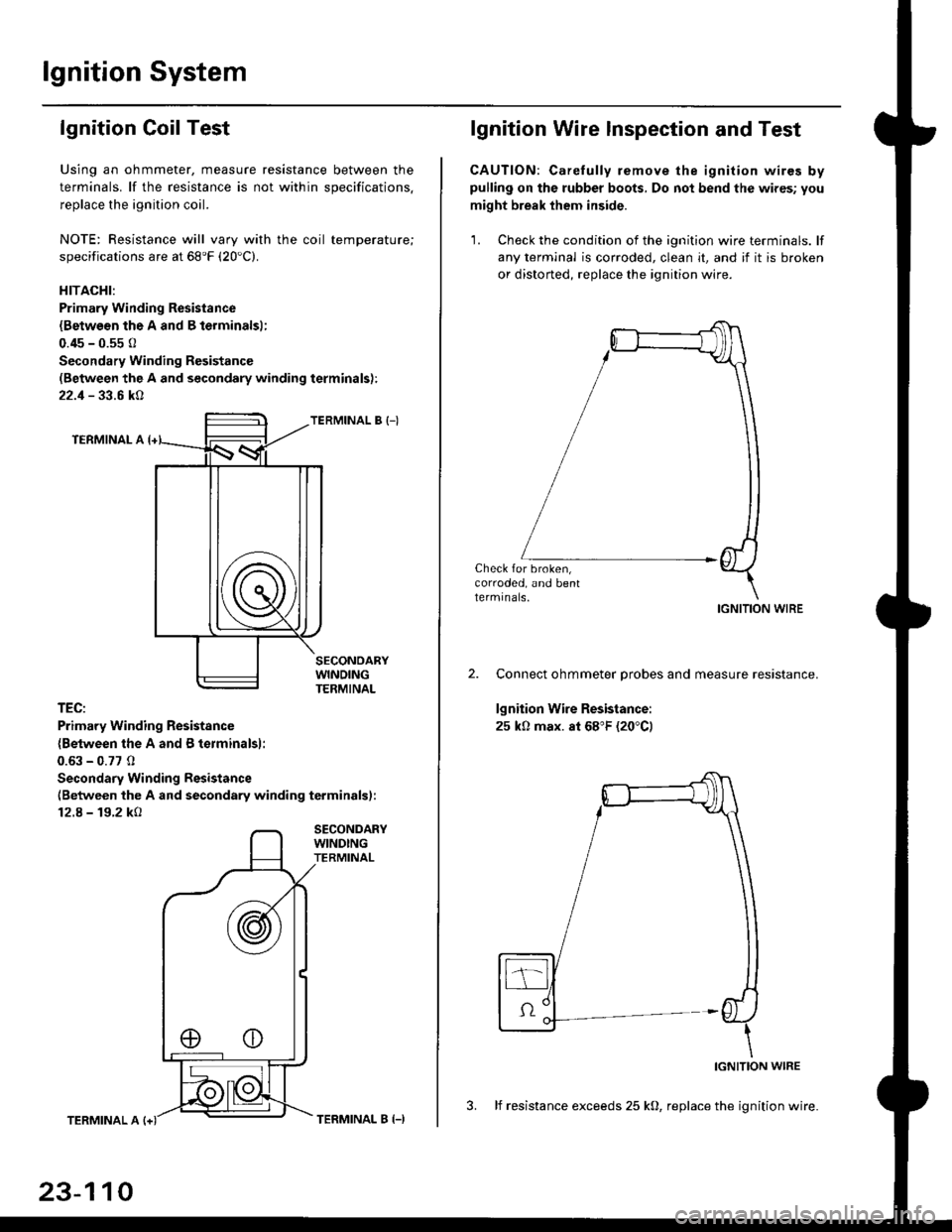
Using an ohmmeter, measure resistance between the
terminals. lf the resistance is not within soecifications.
replace the ignition coil.
NOTE: Resistance will vary with the coil temperature;
specifications are at 68'F (20'C).
HITACHI:
Primary Winding Resistance
{Betwesn the A and B lerminalsl;
0.45 - 0.55 0
Secondary Winding Resistanc€
(Between the A and secondary winding terminals):
22.1 - 33.6 kA
TERMINAL B {-)
TERMINAL A
TEC:
Primary Winding Resistsnce
{Between the A and B terminalsl:
0.63 - 0.77 0
Secondary Winding Resistance
(Between the A and secondary winding terminals):
12.8 - 19.2 kO
SECONDARYWINDINGTERMINAL
TERMINAL A
23-110
TERMINAL B (-)
lgnition Wire lnspection and Test
CAUTION: Carelully remove the ignition wires bypulling on the rubber boots, Do not bend the wires; you
might break them inside.
'1. Check the condition of the ignition wire terminals. lf
any terminal is corroded, clean it, and if it is broken
or distorted, replace the ignition wire.
Check for broken,corroded, and bentlermrnals.IGNITION WIRE
Connect ohmmeter probes and measure resistance.
lgnition Wire Resistance:
25 k0 max. at 68"F (20"C)
IGNITION WIRE
3. lf resistance exceeds 25 kO, replace the ignition wire.