Page 955 of 2189
Electrical Troubleshooting ('99 - 00 Models)
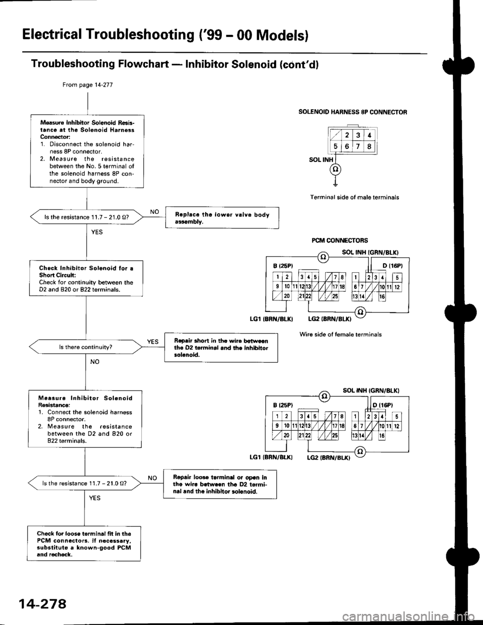
Troubleshooting Flowchart - Inhibitor Solenoid (cont'dl
SOLENOID HARNESS 8P CONNECTOR
SOL INH
Terminal side of male terminals
Wire side oI temale terminals
Mersure Inhibitor Solenoid R6b-t.nce at the Solenoid Harne3sConn€ctor:1. Disconnect the solenoid har,ness 8P connector,2. Measure the resistancebetween the No.5 terminal ofthe solenoid harness 8P con-nector and body ground.
ls the resistance 11.7 - 21.0 O?
Check Inhibitor Solonoid fo. .Short Ci.c!it:Check for continuity between theD2 and 820 or 822 terminals.
R.p.ir 3hort in thc wire botwaanth€ 02 t.rminal and the inhibhotsolenoid.
Measur6 Inhibitor SolenoidRe3istance:1, Connect the solenoid harness8P connector.2, Measure the lesistancebetween the D2 and 820 or822 terminals.
Rcpair loo3. tarminal or opan intho wha brtw.€n tho D2 to.mi-nal .nd tho inhibitor lolonoid.
ls the resistance 11.7 - 21.0 O?
Check fol looso torminal fit in thePCM connectors. lf n€cessaay,substitute a known-good PCMand r€check.
Ftom page 14-277
LGl IBRN/BLKI
LGl{BRN/ALKI
B t25P) ll D t16P)
B t25Pt otl6Pt
14-274
Page 1093 of 2189
Steering Column
I
Removal/lnstallation
SRS components are located in this area. Review the
SRS component locations, precautions, and proceclures
in the SRS sectron (24) before pertorming repairs or ser-
vice.
NOTE: Before removing the steering column for SRS,
remove the driver's airbag assembly and cable reel lsee
section 24).
1. Remove the steering wheel (see page 17 35).
2. Remove the driver's dashboard lower cover and
driver's knee bolster (see section 20).
3. Remove the combination switch assembly from the
steering column sha{t by disconnecting the connec-
tors.
4. Disconnect the ignition switch connectors.
5. Remove the steering joint cover.
6. Bemove the steering joint bolls.
7. Disconnect the steering ioint by moving the joint
toward the column, and remove it from the column
shaft.
8. Remove the steering column by removing the
attaching nuts and bolt.
UPPER
RETAINING COLLABNOTE: Take care not to let the
retaining collar fall out ofposition during installation.
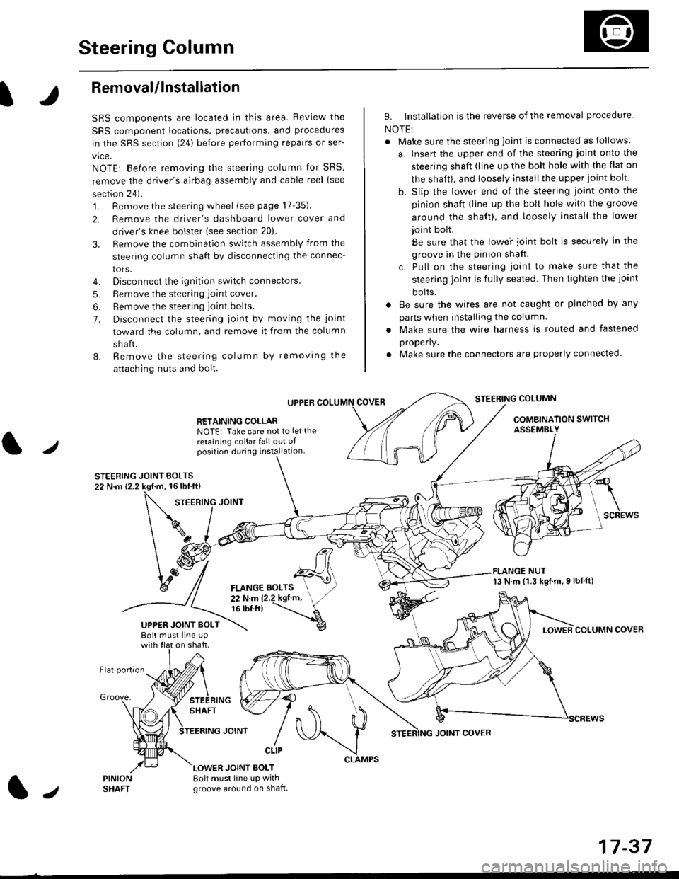
STEERING JOINT BOLTS22 N.m {2.2 kgf.m, 16lbtft}
9. Installation is the reverse of the removal procedure
NOTE:
. Make sure the steering joint is connected as follows:
a. Insert the upper end of the steering ioint onto the
steering shaft (line up the bolt hole with the flat on
the shait), and loosely install the upper joint bolt.
b. Slip the lower end of the steering joint onto the
pinion shaft (line up the bolt hole with the groove
around the shaft), and loosely install the lower
joint bolt.
Be sure that the lowei joint bolt is securely in the
groove in the pinion shaft.
c. Pull on the steering joint to make sure that the
steering joint js fully seated. Then tighten the ioint
bolts.
. 8e sure the wires are not caught or pinched by any
parts when installing the column
. Make sure the wire harness is routed and fastened
properly.
. Make sure the connectors are properly connected.
STEERING COLUMN
COMBINATION SWITCHASSEMBLY
FLANGE NUT13 N.m {1.3 kgl.m.9 lbf ft)
COLUMN COVER
FLANGE BOLTS22Nm12.2kgl'm,16 tbt.tr)
UPPER JOINT BOLTBolt musl line upon shaft.
Groove.
LOWER JOINT BOLT8oh must line up wrthgroove around on shaft.
CLIP
J
JOINT COVER
17-37
Page 1296 of 2189
Carpet
Replacement
SRS components are located in this area. Review the SRS
component locations, precautions, and procedures in the
SRS section {24} before performing repairs or service.
1. Remove:
. Front seat (see page 2O-7 4l
. Rear seat cushion (see pages 20 79, 80, 81)
o Kick panel (see pages 20-59, 60, 61)
o Center pillar lowertrim panel i4D, see page 20-59)
. Front seat belt iower anchor (2Dl3D, see page 20-
86)
. Side trim (see pages 20-59, 60,61)
o Front and rear consoles
. Console panel
Remove the SRS unit covers.
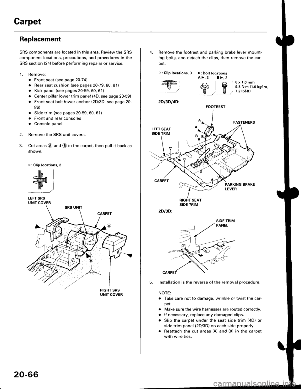
Cut areas @ and @ in the carpet, then pull it back as
snown.
>: Clip locations,2
2.
3.
-lM- IlMt l
ry-l
LEFT SRSUNIT COVER
20-66
4. Remove the tootrest and parking brake lever mount-
ing bolts, and detach the clips, then remove the car
pet.
>:Clip localions,
:ft
\/l
2D l3D l4D:
3 >: Bolt locationsA>.2 A>,2
3 l6x10mm
e2 Y 9.8 N.m r1.o kgr'm,
H ) E / 7.2tbtrtl::a /
5.
2D I3D:
Installation is the reverse of the removal procedure.
NOTE:
. Take care not to damage. wrinkle or twist the car-
pet.
. Make sure the wire harnesses are routed correctly.
. lf necessary, replace any damaged clips.
. Slip the carpet under the seat side trim (4D) or
side trim panel (2Dl3D) on each side properly.
. Reattach the cut areas @ and @ in the carpet
with wire ties.
FOOTREST
SIOE TBIM
Page 1297 of 2189
Consoles/Console Panel
Replacement
NoTE:Takecarenottoscratchthefrontandrealconso|es,frontseatandre|atedparts.
Disassemble in numbered sequence
>: Screw locationsa>,8 B>,4>: Clip locationsA>,2 B>.2
' nnffir
:__)
"=)
:)
::r_l REAB CONSoLE(with armrest)
lnstallation is the reverse of the removal procedure
NOTE:
. lf necessary, replace any damaged clips.
. Make sure the wire harnesses are not pinched.
. Make sure the connector is connected properly.
€] FRONT CONSOLERemove the shift lever knob (M/T)
{.
I
I
20-67
Page 1300 of 2189
Dashboard
Gomponent Removal/lnstallation
(cont'd)
Center panel removal:
1. Remove:
. Center dashboard lower cover (see page 20-69)
. Radio {see section 23)
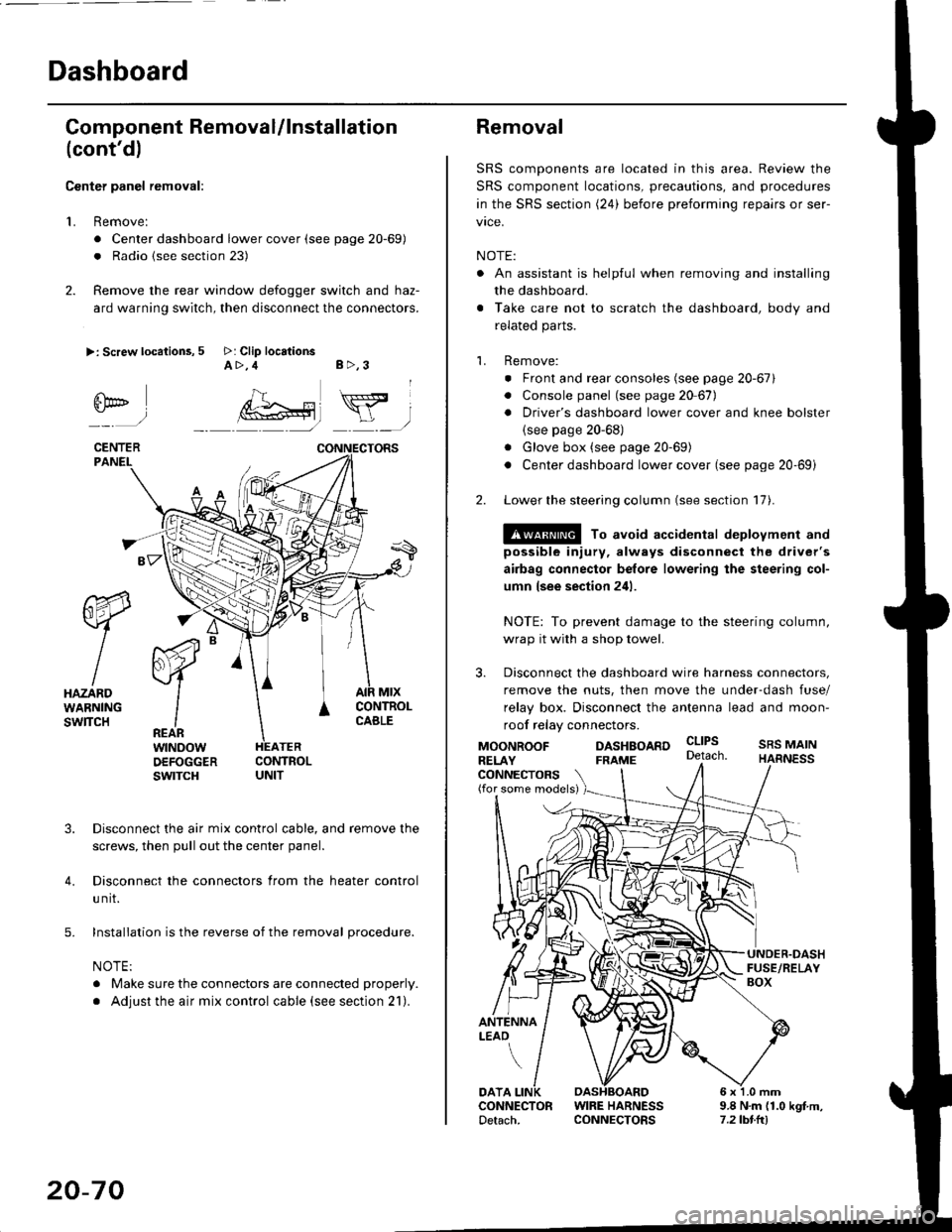
2. Remove the rear window defogger switch and haz-
ard warning switch, then disconnect the connectors.
>: Screw locations, 5 >: Clip locationsA>,4 B>,3
fii*-)
CENTERPANEI.
rt-xR.
W
IHAZARDWARNINGswlTcH
r44 "
F.IZvl
IIREARwtNoowOEFOGGERswtrcH
MtxCONTNOLCABLE
3. Disconnect the air mix control cable, and remove the
screws, then pull out the center panel.
4. Disconnect the connectors from the heater control
u nit.
5. Installation is the reverse of the removal procedure.
NOTE:
. Make sure the connectors are connected properly.
. Adjust the air mix control cable (see section 21).
20-70
Removal
SRS components are located in this area. Review the
SRS component locations, precautions, and procedures
in the SRS section (24) before preforming repairs or ser-
vice.
NOTE:
. An assistant is helpful when removing and installing
the dashboard.
. Take care not to scratch the dashboard, body and
related parts.
1. Remove:
o Front and rear consoles (see page 20-67)
. Console panel (see page 2O 67),
. Driver's dashboard lower cover and knee bolster(see page 20-68)
. Glove box (see page 20-69)
. Center dashboard lower cover (see page 20-69i
2. Lower the steering column (see section 17).
@ To avoid accidental deplovment and
possible injury, always disconnect the driver's
airbag connector belore lowering the steering col-
umn lsee section 241.
NOTE: To prevent damage to the steering column,
wrap it with a shop towel.
3. Disconnect the dashboard wire harness connectors,
remove the nuts, then move the under-dash fuse/
relay box. Disconnect the antenna lead and moon-
roof relay connectors.
DASHBOARD cltPs
CONNECTORS(for some models)
MOONROOFRELAY
ANTENNALEAO
FRAME
SRS MAINHARNESS
9.8 N.m (1.0 kgf m,7.2lbt.ltl
DATACONNECTOR WIRE HARNESSDetach. CONNECTORS
Page 1302 of 2189
Dashboard
Removal (cont'd)
7. lf necessary, remove the dashboard frame from the dashboard.
>: Screw localionsa>,21 B>,4a: Nut locations, 3
>: Clip locations
l^1./'\
I Shl:' Olb'tvY/l\-]1
ra 6 x '1.0 mm
Yi.!i[11"-"'".
DASHBOARD BRACKETSIDE COVER
Installation is the reverse of the removal orocedure.
NOTE:
. Before tightening the bolts, make sure the dashboard wire harnesses are not pinched.a Make sure the connectors, antenna lead and air mix control cable are connected properly.
FRONT PASSENGER'S
OASHBOARD
20-72
Page 1305 of 2189
Replacement
CAUTION: When prying with a flat-tip screwdrivet, wrap it with protective tape to prevent damage'
NOTE:
. Take care not to scratch the seat covers and body
. Remove the front seat through the door openlng'
Driver's:
NOTE: Refer to page 2O-77 for the seat belt switch harness wiring location'
SEAT CUSHION
CENTER COVER
INNER SEATTBACK
PIVOT NUT8 x 1.25 mm22 N.m l.2.216 tbf.ft)
v
l
35 tbt.ft)
10 x 1.25 mm47 N.m {4.8 kgf m,10 x 1.25 mm47 N.m {i1.8 kgl m,35 tbr.ft)
RECLINE ADJUSTER
LOW
d
ER CAP
l
RECLINE
CONNECTING WIRETo connect, twist 180'
OUTER SEATTRACK
Installation is the reverse of the removal procedure'
NOTE:
. Make sure the bushing and pivot washer
installed ProPerly.. To prevent wrinkles when installing the seat-
back cover, make sure the material is stretched
evenly over the Pad.
. Grease the sliding Portion
8 x 1.25 mm20 N.m 12.0 kgf.m,14 tbt.ft)
are
RECLINEKNOB
(cont'd)
20-75
10 x 1.25 mm47 N.m {4.8 kgf'm,35 tbtftl
Page 1346 of 2189
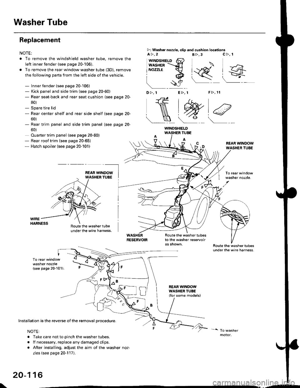
Washer Tube
Replacement
NOTE:
. To remove the windshield washer tube, remove the
left inner fender (see page 20-106),
. To remove the rear window washer tube {3D), remove
the following parts from the left side of the vehicle.
- Inner fender (see page 20-106)- Kick panel and side trim (see page 20-60)- Rear seat-back and rear seat cushion (see page 20-
80)- Spare tire lid- Rear center shelf and rear side shelf (see page 20-
60)- Rear trim panel and side trim panel
60)
Ouarter trim panel (see page 20-60)- Rear roof trim {see page 20-65)- Hatch spoiler (see page 20-101)
(see page 20
WIREHARNESS
>: W.sher nozzle, clip and cushion locationsa>,2B>,3
"J>)
[q@"
F>, 11
c>, 1
wttrtosnteLo 6}usxea =-d
lNozzrE cv
iq
!$e
D>,1 E>, 1
NtW)€
Roote the washer tubeunder the wire harness.
TUBE
A
Route the washer tubesto the washer reservoir
REAB WINDOWWASHER TUBE(Ior some models)
REAR WINDOWWASHER TUBE
washer nozzle.
washer nozzle(see page 20-101).
oo\
Installation is the reverse of the removal procedure.
NOTE:
. Take care not to pinch the washer tubes.
. lf necessary, replace any damaged clips.
. After installing, adjust the aim of the washer noz-
zles (see page 20-117).
20-116
WINDSHIELD
\,--