Page 1808 of 2189

Airbag
Disposal
Before scrapping any airbags (including those in a wholevehicle to be scrapped), the airbags must be deployed. lfthe vehicle is still within the warranty period, before youdeploy the airbags, the Honda District Service Managermust give approval and/or special instructions. Onlv afterthe airbags have been deployed (as the result of vehiclecollision, for example), can they be scrapped.lf the airbags appear intact (not deployed). treat themwith extreme caution.
Follow this p.ocedure:
Deploying the Airbags: In.vehiclo
NOTE: lf an SRS vehicle is to be entirely scrapped, itsairbags should be deployed while still in the vehicle. Theairbags should not be considered as salvageable partsand should never be installed in another veh;cle.
!@ confirm thst oach airbag assembty issecurely mounted; otharwiso. sev€re personal iniurycould result lrom deployment.
1. Disconnect the baftery negative cable, then discon_nect the positive cable.
2. Confirm that the special tool is functioning properlyby following the check procedure on the tool labelor on page 24-'l'l .
Driver's Airbag:
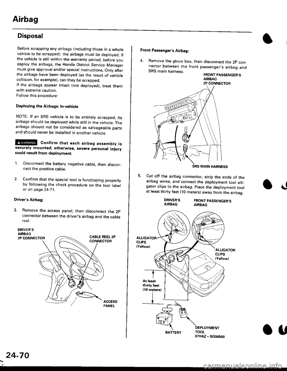
3. Remove the access panel, then disconnect the 2pconnector between the driver,s airbag and the cablereet.
DRIVER'SAIRBAG2P CONNECTOR
24-70
BATTERY.U
Front Passenger's Airbag:
4. Remove the glove box, then disconnect the 2p con-nector between the lront passenger,s airbag andSRS main harness.FRONT PASSENGER'SAIREAG2P CONNECTOB
SRS MAIN HARNESS
Cut off the airbag connector, strip the ends of theairbag wires, and connect the deployment tool alli_gator clips to the airbag. place the deployment toolat least thirty feet (10 meters) away from the airbag.
a!
DRIVER'SAIRBAGFRONT PASSENGER'SAIRBAG
ALLIGACLIPS(Yellow)ALLIGATORCLIPS{Yellowl
At loastthiny toet(10 metorsl
Page 1827 of 2189

How To Use This Manual
Symbols
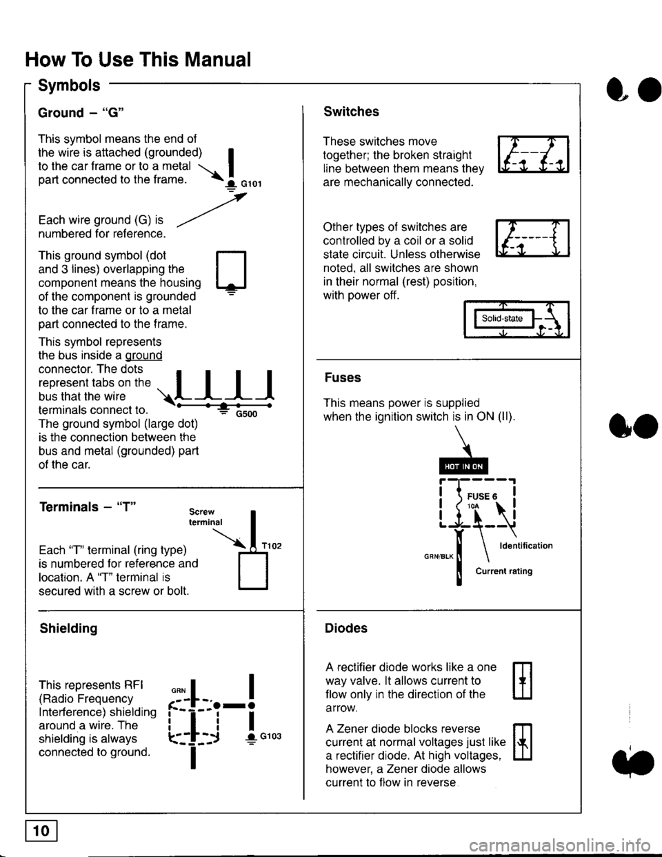
Ground - "G"
This symbol means the end ol
the wire is attached (grounded) Ito the car frame or to a metal I
part connected to the frame. \i oro,|
-t'
Each wire ground (G) it --/
numbered for reference.
oo
Switches
These switches move
together; the broken straight
line between them means the,
are mechanically connected.
Other types of switches are
controlled by a coil or a solid
state circuit. Unless otherwise
noted. all switches are shown
in their normal (rest) position,
with power off.
This ground symbol (dot
and 3 lines) overlapping the
component means the housing
of the component is grounded
to the car frame or to a metal
part connected to the frame.
This symbol represents
the bus inside a ground
connector. The dots I
i:l*,':1,'^:*,:"
;"
r"L I I I
terminals connect to.
The ground symbol (large dot)
is the connection between the
bus and metal (grounded) part
of the car.
Terminals - "T"
ffi
ffi
Solid-state
Fuses
This means power is supplied
when the ignition switch is in ON (ll).
Current rating
Diodes
A rectifier diode works like a one
way valve. lt allows current to
llow only in the direction of the
arrow.
A Zener diode blocks reverse
current at normal voltages just like
a rectifier diode. At high voltages.
however, a Zener diode allows
current to f low in reverse
oo
Each "T" lerminal (ring type)
is numbered for reference and
location. A "T" terminal is
secured with a screw or bolt.
Shielding
This represents RFI
(Radio Frequency
Interference) shielding
around a wire. The
shielding is always
connected to ground.
f--l;j-i",..
I
,,,,
T
Page 1855 of 2189
ie----1
\{
i____J
WIIT/FED
FUSE 54OPNOI404
c351
vtEw 34
c419
FUSE 52HOAT. ST(IP LT154
c352
vlEw2/
FUSE 53NAZABO
c352
vtEw 27
c4't 1
UNDER-HOODFUSE/RELAYgox
15
_",":IWH'/BLK
(Not (Not 7Used) Used)
UNDER-DASHFUSE/RELAY BOXPHOTA 58
c419 C926110!0,63 oPTtoNCONNECTOBPHOTO 62
WHT/GRN
{with CruiseControl 4)
WHT
'9&'98 modelspre'wked toracteEsorysacurity system
""'l
o
;l10
vtEw 6a
cs16
'99'0O modelspre-wired foraccessorysecurfy system
SECURIrySYSTEMCONNECTOR(oPTroN)Page 133-4
ll
tl
BRAKESWITCHPages 23-4 , 24 4 ,25-4, 34-1, 39,39-4, 39-8, 39-12,44-2,110-15,110-16, 110 17,'138, and 138-1
ll
ll
HAZARDWARNINGswrTcHPage 110'6or 110-8vtEw 32
,rr rrRt3,:i]L-
SECURITYSYSTEMCONNECTOR(oPTlON)Page 133-4
r----=-:'l
I Uoll UonEcI I
tlL------JHORN BELAYPage 40, 40-1,ot 40-2
PHOTO 58 (96 97 models)PHOIo 129 (98 mode)
c447
wEw 5a
sEcuRrwSYSTEMCONNECTOR(oPTroN)Page 133
10-13
Page 1864 of 2189

cRutsECONTROLMAINswrTcHPage 34
tl
ll
1Y
. - -' accessory
: security system :
i secun,rY ;
: SYSTEMi coNNEcroR :' (oPTroN)' Page |33
: '. rg;'3,, :, I vrfl,v 58
ili; . ----+
REARWINDOW DASH LIGHTSDEFOGGER BBIGHTNESSSWITCH CONTROLLER
:93' :gl"' Goug:*:FTi\" f3$??'o"'
llll bi:8d;fttie-i:9-9{EJ
aaal ,"|;fl9,,ff%;"
:f :1'L;,:;;-;__:_:::J
i:ir .:,;,-rr-E:
f
,-T,-"T-'-.
[_j,I=
,
lii
f ::'* ,I., l, I -l*,.Oerminals l '6)
'96-'98 modelspr+wi.ed tor
'99'00 modelspre-wired lor-_----accessory, security system
I srcunrw sEcunrrY :, SYSTEM SYSTEM ;i CONNECTOR CONi{ECTOR '' (oPTroN)
: Page 133-4
PHO|O136'
I- ABS -.
.-- USA: LX. -' .-' vo-Jl --', EX, and ilx mooers
vtEw 56
MOONROOF
!!P:',t MooN.
i*:r?, 33,o+"
'iii?,;) i??3;?'
' STEREO' RADTO TUNER ' ' DASH LIGHTS ,' P.da11o-, ' ' BRIGHTNESS '', ,;;;;- - : : coNTRoLLER '', v,iw;;" i i eage tte.t :, r-1 ,r r-1
: | | ::l I I
: | | ':l I. L-J . L-J
i"'r ii'I i
MOON-ROOFOPENRELAYPage 122ot 122-1
vtEw 15
ll
ll
'+--a ---'-*-'O
c50tPHOIO 60vtEw 55
r-1 r-1
tttl
lttlL-J L-J
,l
POWENwrNDowNELAYPage 120?HOm 59
ll
tl
.LIJ
14-7
Page 1939 of 2189
Horn
- '96-'97 Models
UNDER.HOODFUSE/RELAYBOX
c353PHOTOs
See PowerOistribution,pag610-13.""^T.!,-
HORNRELAYPHA|O 58
c214
vtEw21
BLU/FEO
1
VHT/qRN
I1
WHT/qRN
: :i-I:::--li i ! !'-'! fevtess
! a;fi."*
,,lr--J I::.-------J. , STEREO RAOIO TUNER
| | vtEw 68
HORN
l
h: c4o1PHQ|A 57
c430
Sse CruiseControl
Vehicles pre-wired ---lor accessorysecurity system
BLU
GBY
------- J
- -.! STEERINGWHEEL
6 g c411
| _vtEw 60
a,---li
cnv I
18 A C516
sEcuRtwSYSTEMCONNECTOR(oPTroN)PHO|O 73VEW 5A
40
Page 2002 of 2189
Fog Lights
_ Vehicles pre'wiredfor accessorysecurity system
SECURITY SYSTEMCONNECTOR(oPT|ON)
"!'19*13*
u,.*,"
a
c403
----.t COMB|NAT|ON
: swrrcHI PHOIOT2
lvtEw u
I
I
FOG LIGHTIN-LINE FUSE
FUSFI H,'lt.cw 8llaa
BLKI .--<
t_G2O2
gee GroundDistribution,pag€ 144.
i t-' BsJ:?'tr! li[?i,i'*'LJ------J
_ _tlI',-Yfi::"* *,*,,
a,
ot'
tttr(
---g-----J _- -"il( - see H€dbnt
;eo'q;r. I-) oaoe loo.
See Headlights '(Canada)
l-l 1 aeomnr
k-j'/,-dl15 llJ - - oplronal Fog Light swttch Harness - - -.I UNOER.DASH
I FUSE/RELAY
FUSE2l I BOx
R H/r- i PHoro 5errow BEA
I
---!':--J--1frf':l,"
i::.,.n.*BEo,naHT I !7
*':#i,!J
^ L--8-
i33o,,nno t f-
"-'-:E+
1 10-10
Page 2004 of 2189
Headlights
- Coupe and Sedan
Vehicles pre-wired- - - for accessorysecurity system
5 f| C419 PHQ|O63 vtEW4s
UNDER-HOOD| / FUSE 48 | FUSE/RELAY: HEADLTGHT :BOXI I 3oa I pHoroT
LJ----JI Y C3s2wHrl PYo-rg8- ulEY:?- - - - - - canadaWHT
Head-ligtrtSwlich
COMBINATIONLIGHTswrTcH
".;L
L--{..---1 Y Cs01
".o,o"n I i[?,lo,uo ^..?fiurti
ce.l, *i;[fl?ive /a V|EW z1
i--r------''i
/A xrcx geru
;".1p$31"f'""InoFY;�]j:::-:
T_l Eqr I--g------J
RIGHTHEADLIGHT
lL
r-: G401PHOTO 57
See GroundDistdbution,page 14-4.
Soe GroundDistribution,page 14-4.
SECURIry SYSTEMCONNECTOR(oPTloN)i t-'d*ltr! lF"{il'.]'*'
nero't t-+- *.oo*jpinx I pl66 HEAo J cmx
- Canada -
---J4- ----J See HeadliohtB1 Y Swirch,-.^^-- I# oao6 100.
FUSE 21F i/tIOW AEAM
FUSE 4B H/LHIGll BEAM
UNDER.DASHFUSE/RELAYBOX
1IIGH
110-12
Page 2030 of 2189

Power Door Locks (cont'd)
Keyless Entry Does Not Work In Any
Mode
NOTE: Before beginning, verify that all the
transmitters are programmed to the vehicle.
1 . Does the radio work properly?
Yes - Go to step 9.
No - Go to the neld step.
NOTE: For steos 2 - 8. refer to the schematic dia-
gram for the Stereo Sound System on page 150.
2. Are fuses 28 (in the under-dash fuse box) and
fuse 47 (in the under-hood fuse box) OK?
Yes - Go to step 4.
No - Replace the blown fuse, then go to the
nen steo.
3. Does the fuse blow again?
Yes - Locate and repair the short.
No- Retest the system.
4. ls the vehicle equipped with the optional security
system?
Yes - Go to the next steP.
No - Go to steD 6.
5. Does the keyless entry work correctly when the
security control unit connector is disconnected?
Yes - Faulty security system, go to security
system for f urther troubleshooting.
No - Go to the next step.
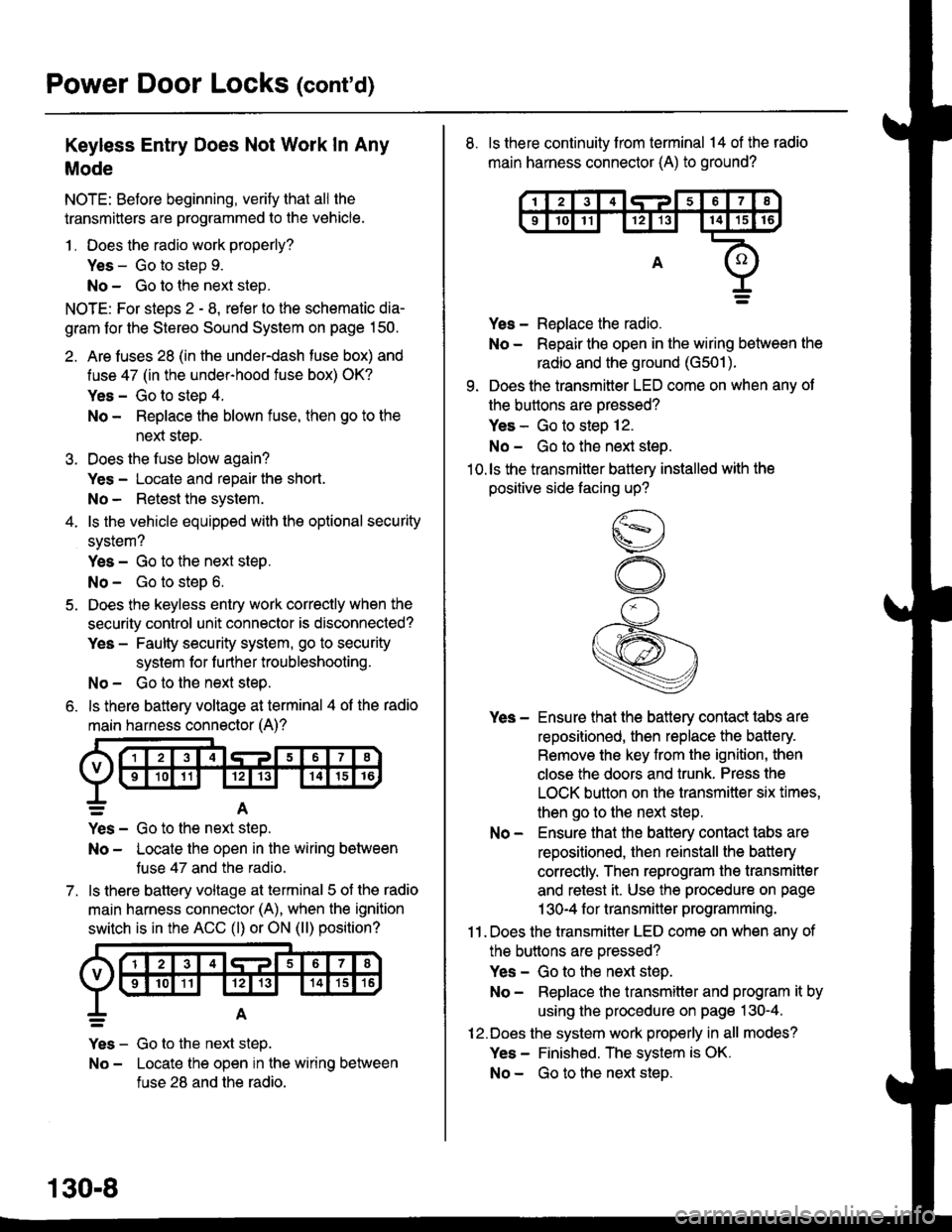
6. ls there battery voltage at terminal 4 of the radio
main harness connector (A)?
7.
=A
Yes - Go to the nen step.
No - Locate the open in the wiring between
tuse 47 and the radio.
ls there battery voltage at terminal 5 of the radio
main harness connector (A), when the ignition
switch is in the ACC (l) or ON (ll) position?
Yes - Go to the next step.
No - Locate the open in the wiring between
fuse 28 and the radio.
130-8
8. ls there continuity from terminal 14 of the radio
main harness connector (A) to ground?
Yes - Replace the radio.
No - Repair the open in the wiring between the
radio and the ground (G501).
9. Does the transmitter LED come on when any ot
the buttons are oressed?
Yes - Go to steo 12.
No - Go to the next steo.'10.ls the transmitter battery installed with the
positive side facing up?
Yes - Ensure that the battery contact tabs are
repositioned, then replace the battery.
Remove the key from the ignition, then
close the doors and trunk. Press the
LOCK button on the transmitter six times,
then go to the next step.
No - Ensure that the baftery contact tabs are
repositioned, then reinstall the batlery
correctly. Then reprogram the transmitter
and retest it. Use the procedure on page
1 30-4 f or transmitter programming.
11 . Does the transmitter LED come on when any of
the buttons are oressed?
Yes - Go to the next step.
No - Replace the transmitter and program it by
using the procedure on page 130-4.
12.Does the system work properly in all modes?
Yes - Finished. The system is OK.
No - Go to the next steD.