1999 HONDA CIVIC Security
[x] Cancel search: SecurityPage 2051 of 2189
V
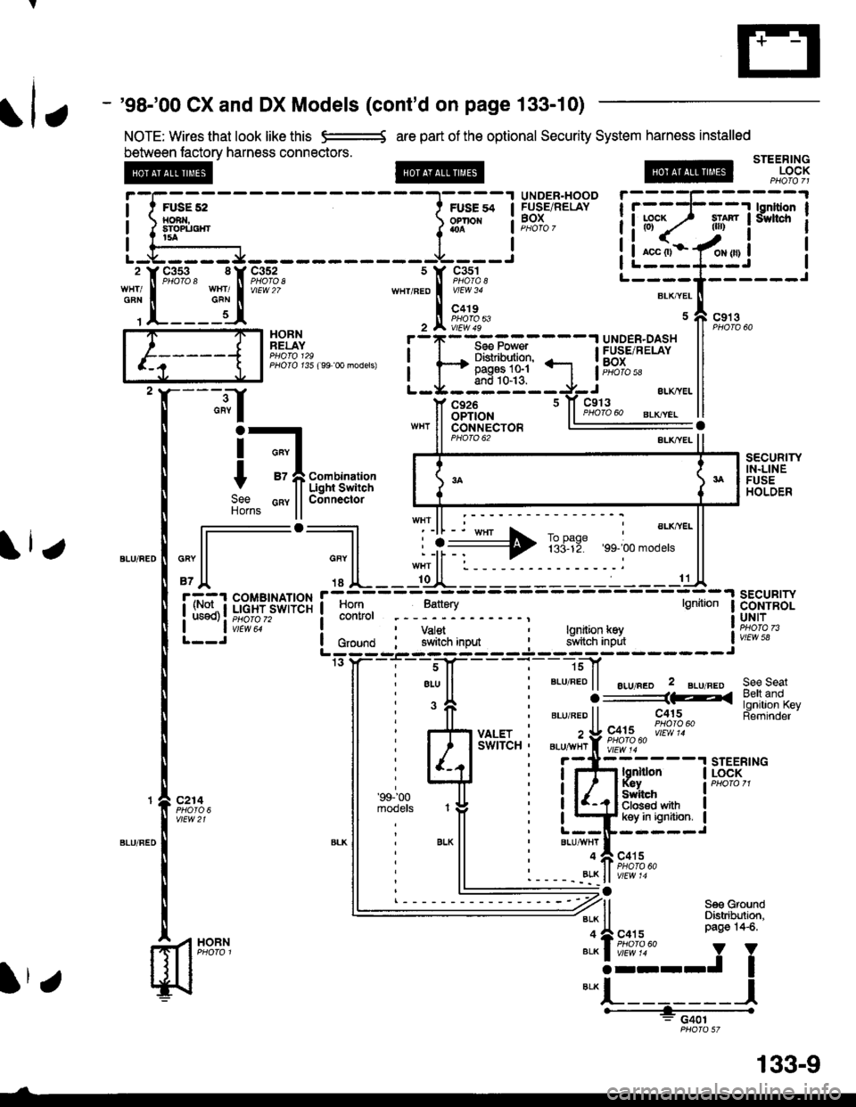
- '98-'00 CX and DX Models (cont'd on page 133-10)
NOTE: Wires that look like this e=-* are part of the optional Security System harness installed
between lactory harness connectors.STEERINGLOCK
UNOER-HOODFUSE/RELAYBOX
HORNRELAY
PHOIO t35 ( 99 0o models)
;.;l
HOBN
c926OPTION
i-t
t -fii;r,'im:";
9"" cnv llConnectorHorns ll
PHO|O 62
sEcuRrwIN.LINEFUSEHOLDER
,"" l-l--';] L ii+ TBriE:,, ;.'".*"' ll
'Jl '' lL--l[JL---:-----------C
i. rl::t ;;;[.?jsor+3r i
lff],
-,
;,:"1.
- . :-
- -
;_:
- - -
tt*
I ii}"*:*'t--J'''*uo lc,o,na i Y#,iln,"o* i 9JlflB'],iff, iw,E"L:;; -'- ---J ---.l.--- -J------- Jrs y- - -i'. - -s-J[- - - -
l-
- ]sf
ll ; eLu ll ' BLU REo | | ".r,".o 2 gLu neo see seat
i 'fi i ".,".oii----iiiu
-
[tJ.li'fll5"t
i r{i y*sr.. : z!9X;2""|"i!'}?.""
ll i l/rlu'-'u"i
"i-jttz---'rsrEER,
Fii;i," ll ;i'".'J^ ,# i iQffi*"it*"ll : ll L--IF-----J*-
ll
' BLK
ll i
"'u*TI
"o,u
' 11 ' --- --;' Bett and
SWITCH ' BLU^YHr f i;;;i;" l{ -l-'- ' -';r{iss"-
STEERTNG
, r atv r- lt PHofo 60. - - - -. _8!K ll v/Ew '4
: G401
fl
-1[::_5J*nt
s Y c3s1
,n"r,".o I i[o"to,'
, tr ft?;","
liuF;lt"ls'rs?rl
iL:"::Ifui i'--T'Il,].----r
Itr
133-9
Page 2052 of 2189
Security System
SECURITY
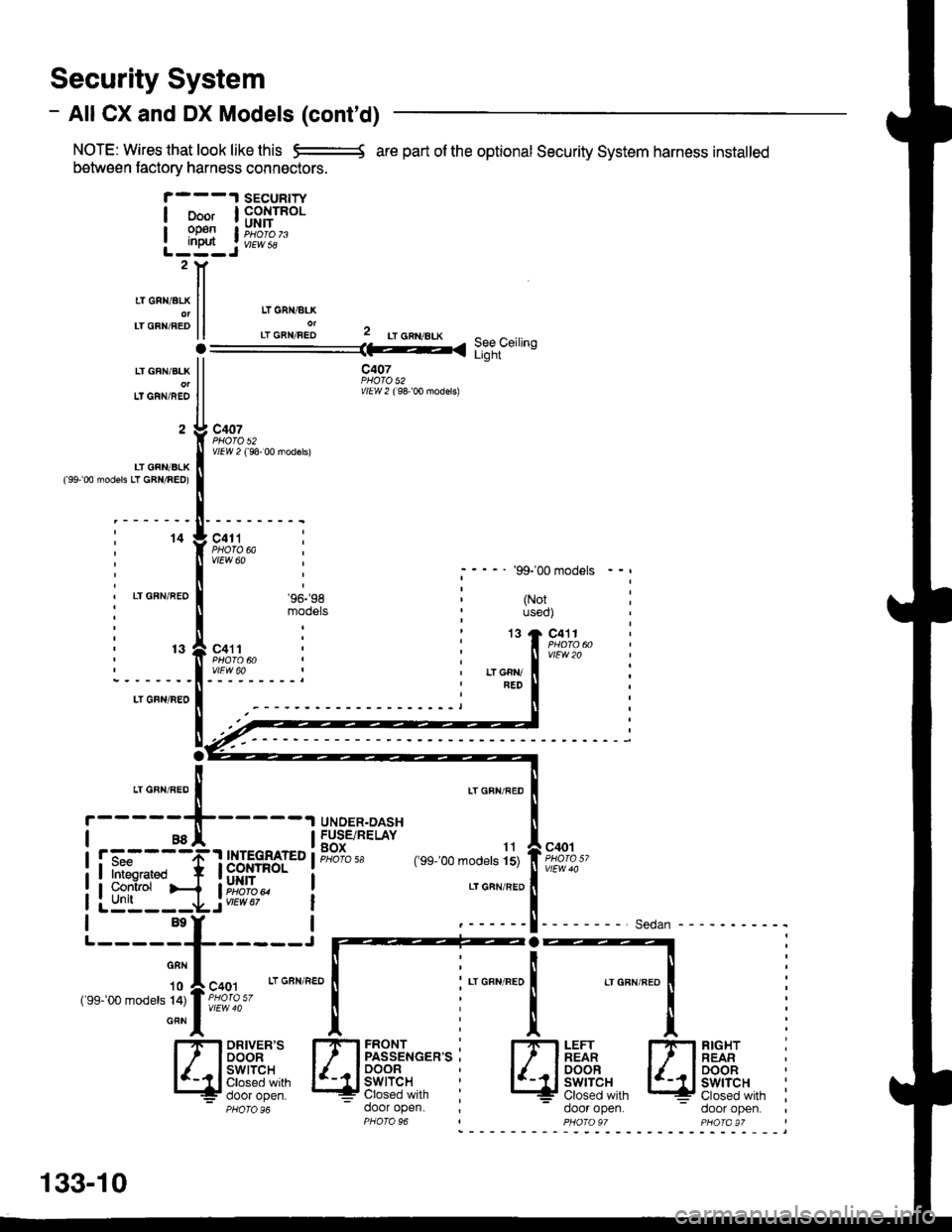
- AIICX and DX Models (cont'd)
NOTE: Wires that look like this -:= are part of the optional Security System harness installed
between factorv harness connactors.
LT GFN/BLK
Lf GRN/REO
2
LT GFN/BLK('99' 00 modsls LT GBN/RED)
14
LT GFN/REO
13
c407PHO|O 52Y/El4 ? ( 98' 00 mod€rs)
c41tPHO|O 6AvtEw 60'99-'00 models
(Notuseo)
c411
vtFw 20
LI GFN/BEO
a, o^n,"ao I
r-----{-
I asl
RIGHT :REABDOORswtTcHClosed with ;door open.- door open.
IT
REAR
SWITCH= Closed with
-----1
LT GBN/RED
LTGFN/FED
UNDER.OASHFUSE/RELAYBOX 11PHoro 5a (,99_,00 models 15)
LT GAN/BED
FRONTPASSENGER'SDOORswtTcHClosed withdoor open.
c40'r
rui=ifl
Sedan - - -
HH
l' il- - - -l.- 1 INTEGRAT€D
ififlLliF"#t::-
fTl33'J"*'�'
lldi$"",""',:;ll
PHO|O96
133-10
I PHO|OqT PHO|A9T
Page 2054 of 2189
Security System
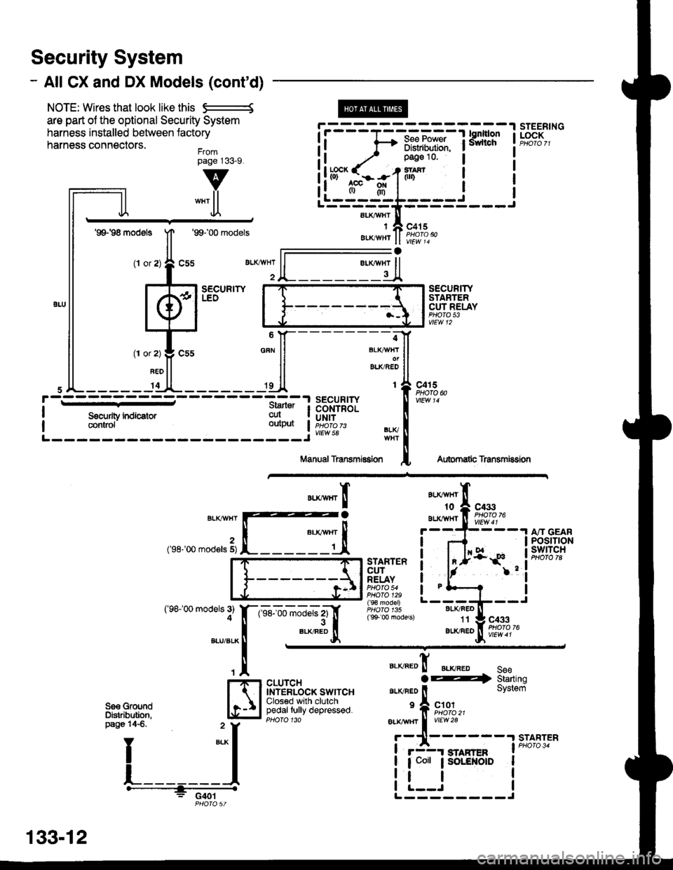
- All CX and DX Models (cont'd)
NOTE: Wires that look like this S--------S
are part ol the optional Security System
harness installed between lactory
harness connectors.Frompage j33_9.
@
aLI(AVHI
IAIKWHT
STEERINGLOCK
v
""'ll
'99198 models
(l or
1T
Jl.
'99100 models
sEcuRrwLEO
c415
vlEw 14
l-
SECURITYSTARTERCUT RELAYPHO|O 53vtEw 12
BLI(FEO't1
au(/FEo
c433
Aubrnatb Transmission
c4r 5PHOTO N
AU(WHT't0
BLXAVI{TBLKT'!VHT
2('98-'00 mod€ls 5)
('98100 models 3)4
A"IT GEARPOStTTONswtTcH
".**"rI
[ :,iSTARTERCUTRELAYPHO|O 54PHO|O 129( 9€ model)
( 9+ 00 models)
?
I
I
I
I
I
1-sel-oo rnJ"ls z1'[
".*"9tr
c433
CLUTCHINTERLOCK SWITCHClosed with clutchpedaltully depressed.
".o""0! ".o".0 seeaE4 Starting
ar-rvneo ll System
'f, "";%,,BLK TTBT I
vrEw28
r-11------.|STABTER
! r3r smnren I PHoro 34
| 1 coit ; SoLENOID I
i !.__J iL--------J
"===-F=F*F,Ff
Tfo?"
It -,/ Pase 10 l
!ltb3'-fi:-#-1iln i
ll .",;T; "":JI------;;lt
ll *"ll ll ELKBEDII
,JL----- 'dl*------ 'll t{
paso 14€. " y
I
*-l
L_______l.------+;_ -
PHO|OST
133-12
Page 2055 of 2189
How the Circuit Works
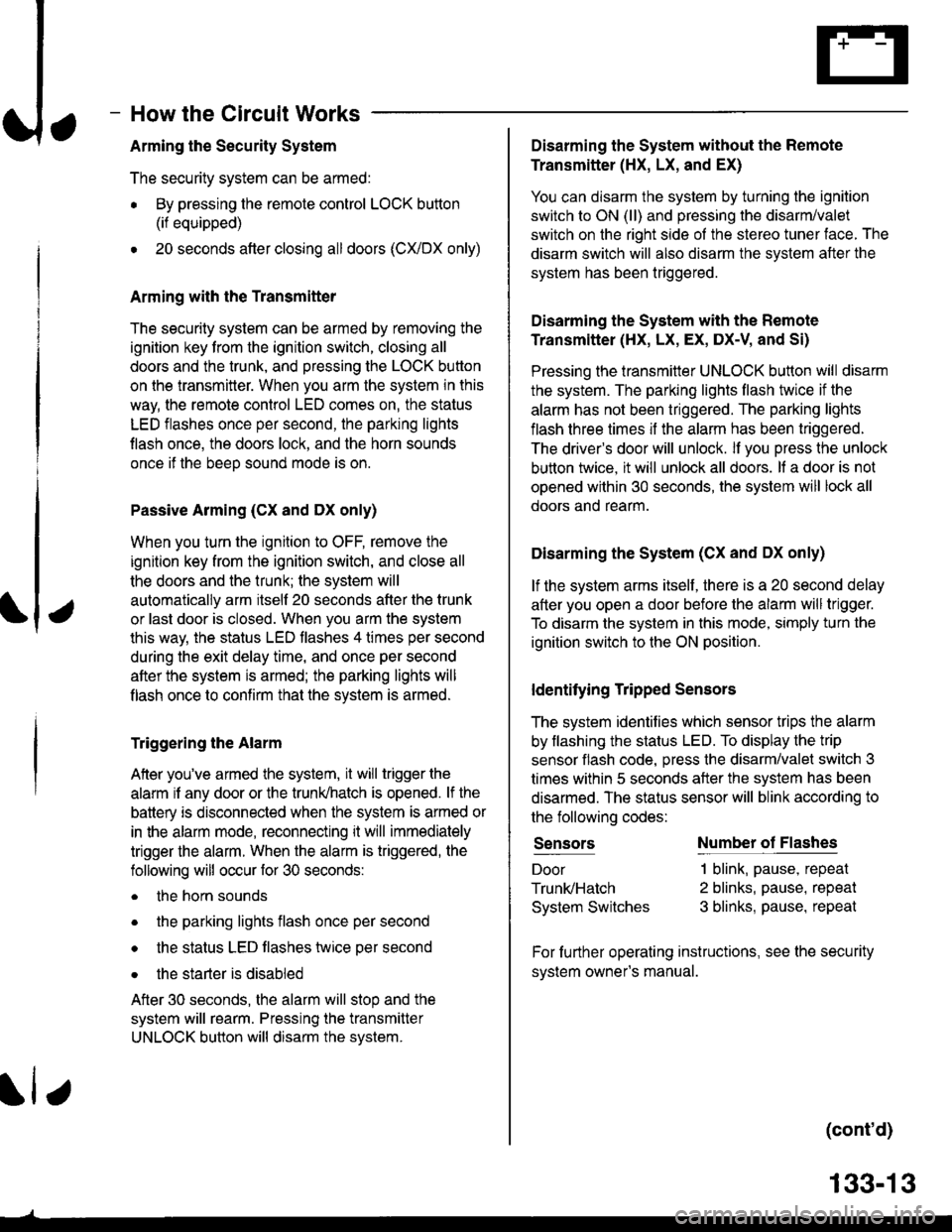
Arming the Security System
The security system can be armed:
r By pressing the remote control LOCK button
(if equipped)
. 20 seconds atter closing all doors (C)UDX only)
Arming with the Transmitter
The security system can be armed by removing the
ignition key from the ignition switch, closing all
doors and the trunk, and pressing the LOCK button
on the transmitter. When you arm the system in this
way, the remote control LED comes on, the status
LED flashes once per second, the parking lights
flash once. the doors lock. and the horn sounds
once if the beeo sound mode is on.
Passive Arming (CX and Dx only)
When you turn the ignition to OFF, remove the
ignition key from the ignition switch, and close all
the doors and the trunk; the system will
automatically arm itself 20 seconds after the trunk
or last door is closed. When you arm the system
this way, the status LED tlashes 4 times per second
during the exit delay time, and once per second
after the system is armed; the parking lights will
flash once to confirm that the system is armed.
Triggering the Alarm
Atter you've armed the system, it will trigger the
alarm if any door or the trunldhatch is opened. lf the
battery is disconnected when the system is armed or
in the alarm mode, reconnecting it will immediately
trigger the alarm. When the alarm is triggered, the
following will occur for 30 seconds:
. the horn sounds
o the parking lights flash once per second
. the status LED flashes hvice oer second
. the starter is disabled
After 30 seconds, the alarm will stop and the
system will rearm. Pressing the transmitter
UNLOCK button will disarm the svstem.
tlr
133-13
Disarming the System without the Remote
Transmitter (HX, LX, and EX)
You can disarm the system by turning the ignition
switch to ON (ll) and pressing the disarm/valet
switch on the right side ol the stereo tuner face. The
disarm switch will also disarm the svstem after the
system has been triggered.
Disarming the System with the Remote
Transmitter (Hx, Lx, Ex, DX-V, and Si)
Pressing the transmitter UNLOCK button will disarm
the system. The parking lights llash t\ivice if the
alarm has not been tnggered. The parking lights
flash three times if the alarm has been triggered.
The driver's door will unlock. lf you press the unlock
button twice, it will unlock all doors. lf a door is not
opened within 30 seconds, the system will lock all
doors and rearm.
Disarming the System (CX and DX only)
lf the system arms itself, there is a 20 second delay
after you open a door before the alarm will trigger.
To disarm the system in this mode, simply turn the
ignition switch to the ON position
ldentitying Tripped Sensors
The system identifies which sensor trips the alarm
by flashing the status LED. To display the trip
sensor flash code, press the disarm/valet switch 3
times within 5 seconds after the system has been
disarmed. The status sensor will blink according to
the followino codes:
SensorsNumber of Flashes
Door
TrunldHatch
System Switches
1 blink, pause, repeat
2 blinks, pause, repeat
3 blinks, pause, repeat
For further operating instructions, see the security
syslem owner's manual.
(cont'd)
Page 2056 of 2189
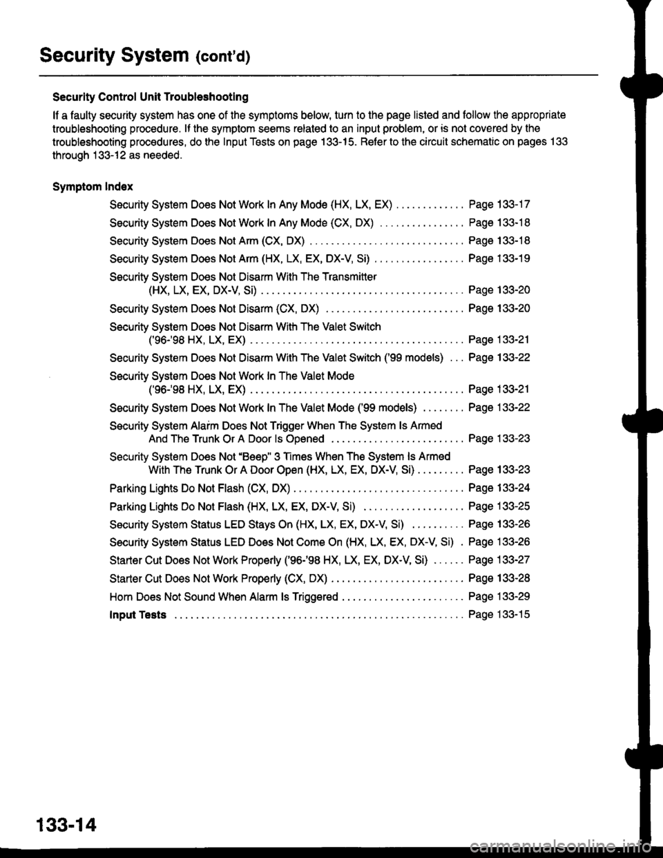
Security System (cont'd)
Security Control Unit Troubleshootlng
lf a faulty security system has one of the symptoms below, turn to the page listed and follow the appropriate
troubleshooting procedure. lf the symplom seems related to an input problem, or is not covered by the
troubleshooting procedures, do the Input Tests on page 133-15. Refer to the circuit schematic on pages 133
through 133-12 as needed.
Symptom lndex
Security Sysiem Does Not Work In Any Mode (HX, LX, EX)
Security System Does Not Work In Any Mode (CX, DX)
Security System Does Not Arm (CX, DX)
Security System Does Not Arm (HX, LX, EX, DX-V, SD
Security System Does Not Disarm With The Transmitler
(HX, LX, EX, DX-V, Si)
Security System Does Not Disarm (CX, DX) . . . .
Security System Does Not Disarm With The Valet Switch
c96-'�98 HX, LX, EX) .
Security System Does Not Disarm With The Valet Switch ('99 models) . . .
Security System Do€s Not Work In The Valet Mode
('96.,98 HX, LX, EX) .
Security System Does Not Work InTheValetMode ('99 models) ........
Security System Alaim Does Not Trigger When The System ls Armed
And The Trunk Or A Door ls Ooened
Security System Does Not'Beep" 3 Times When The System ls Armed
With The Trunk Or A Door Open (HX, LX, EX, DX-V Si)
Parking Lights Do Not Flash (CX, DX)
Parking Lights Do Not Flash (HX, LX, EX, DX-V Si)
Security System Status LED Stays On (HX, LX, EX, DX-V Si)
Security System Status LED Does Not Com€ On (HX, LX, EX, DX-V, Si) .
Starter Cut Does Not Work Properly ('96198 HX, LX, EX, DX-V, SD . . . . . .
Starter Cut Does Not Work Properly (CX, DX) . . . . .
Hom Does Not Sound When Alarm ls Triggered
Input Tests
Page 133-17
Page 133-18
Page 133-18
Page 133-19
Page 133-20
Page 133-20
Page 133-21
Page 133-22
Page 133-21
Page 133-22
Page 133-23
Page 133-23
Page 133-24
Page 133-25
Page 133-26
Page 133-26
Page 133-27
Page 133-28
Page 133-29
Page 133- l5
133-14
Page 2057 of 2189
Ir
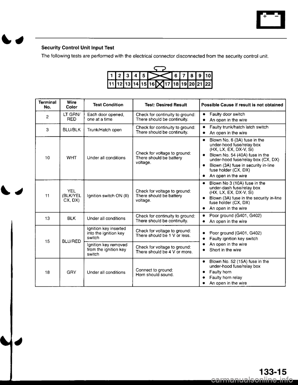
Security Control Unit Input Test
The following tests are performed with the electrical conneclor disconnected from the security control unit.
\;
12345X67I910
1112131415rol171819202122
TerminalNo.WireColorTest ConditionTest: Desired ResultPossible Cause il result is not obtained
2LT GRN/REDEach door opened,one at a timeCheck for conlinuity to ground:
There should be continuity.
Faulty door switch
An open in the wirea
3BLU/BLKTrunUHatch openCheck for continuity to ground:
There should be continuity.
aFaulty trunldhatch latch switch
An open in the wirea
10WHTUnder all conditionsCheck tor voltage to ground:
There should be batteryvoltage.
. Blown No. 6 (3A) fuse in theunder-hood fuse/relay box(HX, LX, EX, DX-V Si)
. Blown No. 54 (40A) fuse in theunder-hood fuse/relay box (CX, DX)
. Blown (3A) fuse in security in-linefuse holder (CX, DX)
. An open in the wire
11YEL(BLK/YEL
cx, DX)lgnition switch ON (ll)Check for voltage to ground:
There should be batteryvoltage.
. Blown No 3 (10A) fuse in theunder-dash tuse/relay box(HX, LX, EX, DX.V, Si)
. Blown (3A) fuse in the security in-linefuse holder (CX, DX)
. An open in the wire
BLKUnder all conditionsCheck for continuity to ground:
There should be continuity.
aPoor ground (G401, G402)
An open in the wirea
t5BLU/RED
lgnition key insertedinto the ignition keyswitch
Check for voltage to ground:
There should be 1 V or less.aPoor ground (G401, G402)
Faulty ignition key switch
An open in the wire
Short in the wire
a
a
algnition key removedfrom the ignition keyswitch
Check for voltage to ground:
There should be 4 V or more.
18GRYUnder all conditionsConnect to ground:
Horn should sound.
. Blown No.52 (15A) luse in theunder-hood luse/relay box
. Faulty horn
. Faulty horn relay
. An open in the wire
133-15
Page 2058 of 2189
Security System (cont'd)
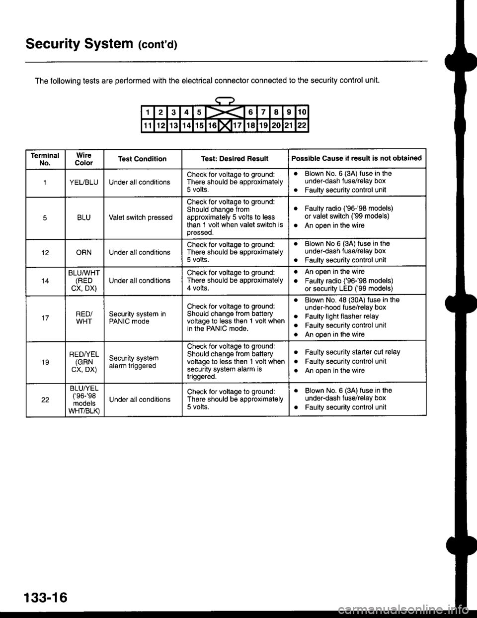
The following tests are performed with the electrical connector connected to the security control unit.
133-16
TerminalNo.WireColorTest ConditionTest: Desired ResultPossible Cause il result is not obtained
1YEUBLUUnder all conditionsCheck tor voltage to ground:
There should be approximately
5 volts.
aBlown No. 6 (3A) fuse in theunder-dash fuse/relay box
Faulty security control unita
5BLUValet switch pressed
Check tor voltage to ground:
Should change from
approximately 5 volts to less
than 1 volt when valet switch isprsssed.
aFaulty radio ('96-98 models)
or valet switch ('99 models)
An open in the wirea
12ORNUnder all conditionsCheck for voltage to ground:
There should be approximately5 volts.
aBlown No 6 (3A) tuse in tho
under-dash tuse/relay box
Faulty security control unito
14
BLU/WHT(BED
CX, DX)Under all conditions
Check for voltage to ground:
There should be approximately4 volts.
. An open in the wire
. Faulty radio ('96198 models)
or security LED ('99 models)
17RED/WHTSecurity system inPANIC mode
Check for voltage to ground:
Should change from batteryvoltage to less then 1 volt whenin the PANIC mode.
aBlown No. 48 (30A) luse in the
under-hood fuse/relay box
Faulty light flasher relay
Faulty security conlrol unit
An open in the wire
a
a
a
19
REDI/EL(GRN
cx, DX)
Security systemalarm triggered
Check tor voltags to ground:
Should change from batteryvoltage to less then 1 volt whensecurity system alarm istriggsred.
aFaulty security starler cut relay
Faulty security control unit
An open in the wire
I
a
22
BLUA/EL/'oa-'oq
mooelsWHT/BLK)
Under all conditionsCheck tor voltage to ground:
There should be approximately
5 volts.
aBlown No. 6 (3A) fuse in the
under-dash fuse/relay box
Faulty security control unita
Page 2059 of 2189
\.
\iu
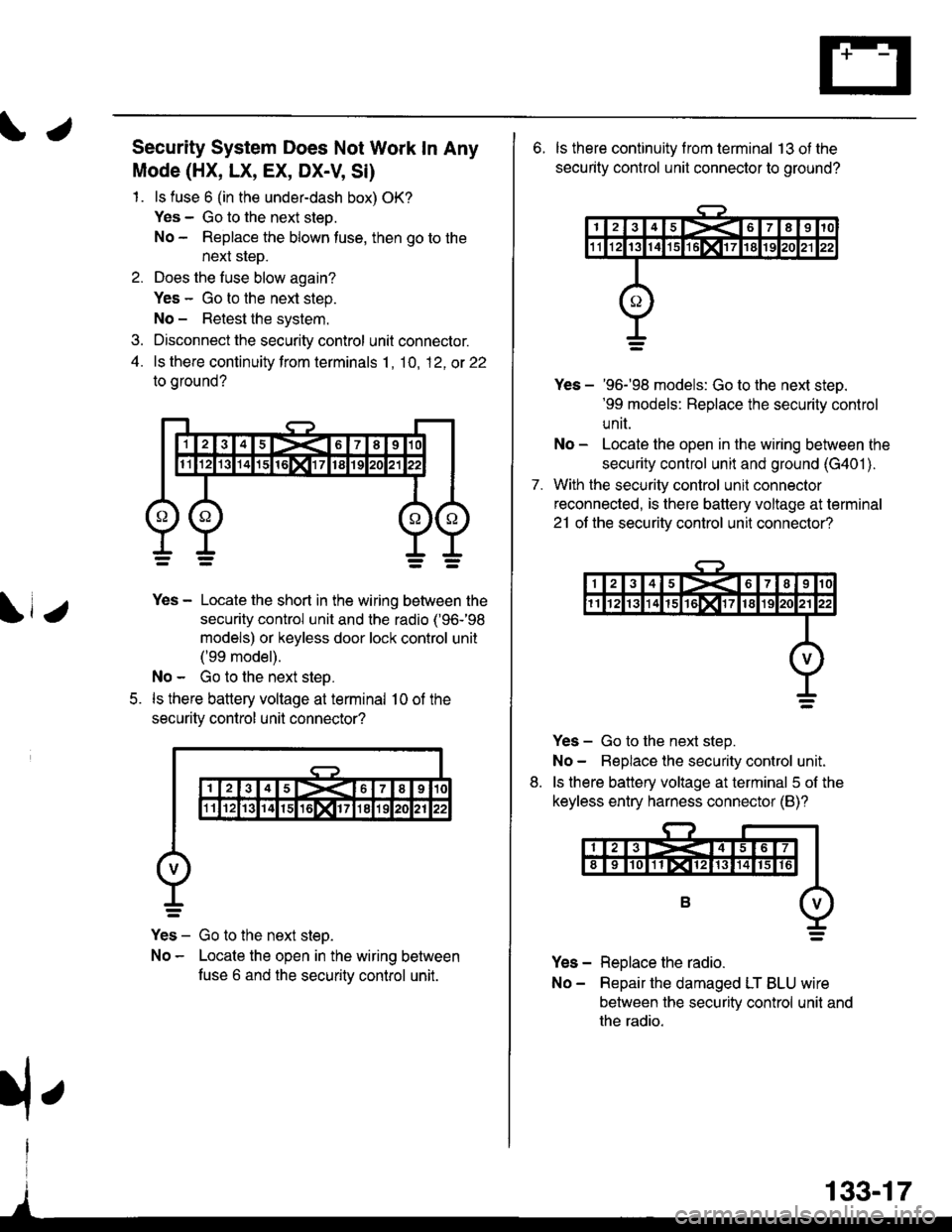
Security System Does Not Work In Any
Mode (HX, LX, EX, DX-V, Si)
1. ls fuse 6 (in the under-dash box) OK?
Yes - Go to the next steo.
No - Replace the blown tuse, then go to the
next sleD.
2. Does the fuse blow again?
Yes - Go to the next step.
No - Retest the system.
3. Disconnect the security control unit connector.
4. ls there continuity from terminals 1, 10, 12, ot 22
to oround?
5.
Yes - Locate the short in the wiring between the
security control unit and the radio ('96-'98
models) or keyless door lock control unit
('99 model).
No - Go to the next step.
ls there battery voltage at terminal 10 of the
securitv control unil connector?
Yes - Go to the next steo.
No - Locate the open in the wiring between
fuse 6 and the securitv control unit.
133-17
rfe
6. ls there continuity f rom terminal 13 ot the
security control unit connector to ground?
7.
Yes - '96-'98 models: Go to the next steD.'99 models: Replace the security control
unit.
No - Locate the open in the wiring between the
security control unit and ground (G401 ).
With the security control unil connector
reconnected, is there battery voltage at terminal
21 ot the securitv control unit connector?
Yes - Go to the next step.
No- Beplace the security control unit.
ls there battery voltage at terminal 5 of the
keyless entry harness connector (B)?
Yes - Replace the radio.
No- Repair the damaged LT BLU wire
between the security control unit and
the radio.
8.