Page 249 of 2189
Exhaust Manifold
Replacement (cont'dl
NOTE: Use new gaskets and self-locking nuts when reassembljng.
CAUTION:
. Check for folds or scratches on the surface ot the gask€t.
. R€place with a new gaskot if damagod,
B16A2 engine:
GASKETReplace.
10 x 1.25 mm44 N.m {4.4 kgt.m,33 tbl.ft)SELF.LOCKING NUT8 x 1 .25 mm31 N.m (3.2 kg{.m, 23 lbf.ft)Replace-EXHAUST MANIFOLDBRACKET
10 x 1.25 mm4{ N.m (4.5 kgf.m. 33 tbt.fil
9-8
Page 250 of 2189
Exhaust Pipe and Muffler
\
Replacement
NOTE: Use new gaskets and self-locking nuts when reassembling
D16Y5, D16Y7 engines:
HEAT SHIELO
6x1.0mm9.8 N.m tl.0 kgf'm,7.2lbf'ft)
EXHAUST PIPE B
EXHAUST PIPE TIP
/
O
6x1.0mm9.8 N.m 11.0 kgt m, 7.2 lbf'ftl
oP----------------8 x 1.25 mm22 N.m 12.2 kg .m,
16 tbf.f Replace.Tighlen the bolts insteps, alternatingside to-side.
8 x 1.25 mm22 N.m 12.2 kgl'm, 16lbl'ttl
Replace.Tighten the bolts in steps,
alternating side-to-side
GASKETReplace.
SELF-LOCKING NUT
8 x 1.25 mm16 N.m 11.6 kgt m, 12 lbt'ftl
Replace.
(cont'd)
9-9
MUFFLER
neOlace. ----------"+@
SELF.LOCKING NUT10 x 1.25 mm33 N.m (3.4 ksd.m,25 lbf.frlReplace.
Page 251 of 2189
Exhaust Pipe and Muffler
Replacement {cont'dl
NOTE: Use new gaskets and self-locking nuts when reassembling.
D16Y8 engine:
MUFFLER
HEAT SHIELD
6x1.0mm9.8 N.m (1.0 kgl m, 7.2 lbf.ft)
EXHAUST PIPE
SECONDARY HO2544 N.m {4.5 kgl.m, 33 lbtftlReplacement, page 9-10
GASKETSReplace.
EXHAUST PIPE A
SELF-LOCKING NUT10 x 1.25 mm54 N.m {5.5 kgl.m, 40 lbtft}Replace.16 N.m {1.6 kgl.m, 12lbf.ft}Replace-
d'*'ou"'"'""'
6x1.0mm9.8 N.m (1.0 ksf m,7.2lbf ft)
8 x 1.25 mm22 N.rn 12.2 kgl.m,16 tbt.ft)Replace.Tighten the bolts insteps, alternatrngside-to-side.
SELF.LOCKING NUT10 x 1.25 mm33 N.m {3.4 kgf.m,25 tbtftlReplace.
TWCinspection, page 9-12
I x 1-25 mm22 N m (2.2 kgf.m. 16 lbfft)
Tighten the bolts in steps,alternating side'to sade.e)GASKETHeplace.
9-10
Page 252 of 2189
816A2 engino:
MUFFLER_.,. EXHAUST PIPE
-/- tlP
g
\6r1.omm
9.8 N m 11.0 kgf'm, 7.2 lbl'ttl
GASKETReplace.
8 x 1.25 mm2. N'm 12.2 kgl-m,t6 tbtf0Replace.Tighten the bolts insteps, alternatrngside-to-side.6x1,0mm9,8 N.m 11.07.2lbl4rl
SELF-LOCKING NUTl0 x 1.25 mm
3:t N.m {3.4 kgf m,24lbf'ftl
ReDlace.PRIMARY IIEATEDOXYGEN SENSOR{PRIMARY HO2S)ll N.m (4.5 kgl.m,33 tbt f0Replacement,
SECONDARY HEATEDOXYGEN SENSOR{SECONDARY HO2SIlrt N.m 14.5 kgf.m,33 rbl.ft)Replacement, page 9-13
GASKETR€place.
twcInspection, page 9-12GASKEISReplace.
SELF.L(rcKNG NUT10 x 1.25 mm5,r N.m 15.5 kgf.m, ,|{} lbf.ft)ReDlace.
8x1.25mm22 N.m {2.2 kgt m, 16 lbf.ftlReplsce.Tight6n the bolts in st6ps,alternating side-to-side.8 x 1.25 mm16 N.m 11.6 kgt.m,12 rbf.ft)F€pl8ce.
I
Replaca.
9-11
Page 262 of 2189
tl
Engine Coolant Refilling and Bleeding
CAUTION: when pouring engine coolant, be sure to
shut the relay box lid and not to lst coolant spill on the
eleqtrical parts or the paint. lf any coolant spills, rinse it
off immediately.
1. Slide the heater temperature control lever to maxl-
mum heat. Make sure the engine and radiator are
cool to the touch.
Remove the radiator caP.
Loosen the drain plug, and drain the coolant'
Remove the drain bolt from the cylinder block'
D16Y5. D16Y7, Dl6Yg sngines:
DRAIN PLUG
0d
I ro
78 N.m {8.0 kgl m.58lbt'ft)
6.
1.
B1642 engin€:
WASHERReplace.
DRAIN BOLT78 N m (8 0 kgf m' 58lbfft)
Apply liquid gasket to the drain bolt threads, then
reinstall the bolt with a new washer and tighten 't
securely.
Tighten the radiator drain plug securely
Remove, drain and reinstall the reservoir' Fill the
tank halfway to the MAX mark with water, then up
to the MAX mark with antitreeze.
(cont'd)
10-7
MAX MARK
Page 267 of 2189
Water Pump
lllustrated Index
NOTE:
. Use new O-rings when reassembrrng.. Use liquid gasket, Part No. 08718 - 0OOl or 087 t8 _ 0003.
O16Y5, D16Y7, D16Y8 engines:
ECT GAUGESENDING UNIT9 N.m {0.9 kgI.m,7 tbnftlApply liquid gasketto the threads.
ENGINE COOLANTTEMPERA TURE (ECT)SENSOR1E N.m (1,8 kgf.m,13 rbttt)
6x 1.0 mm9.8 N.m {1.0 kgf.m,7.2 tbt.ft'|
O.RINGReplace.WATER OUTLETCOVERApply liquid gasketto mating surface.
ECT SW1TCH24 N.m 12.4 kgf.m,17 rbf.ftl
6xl.0mm12 N.m {1.2 kgf.m,8.7 tbf.ft)
6x1.0mm'12 N.m {1.2 kgt m,8.7 lbt fr)
10 x 1.25 mmitl N.m 14.5 kgt m,33 rbf.ftlO.RINGReplace.
10-12
Page 268 of 2189
815A2 engine:
WATER OUTLETCOVERApply liquid gasket
to mating surface.
6x1.0mm9.8 N.m {1.0 kgl'm,7,2 tbl.ftt
ECT GAUGESENDING UNIT9 N.m (0,9 kgf.m,7 rbf.ft)Apply liquid gasket
to the threads.
rENGINE COOLANTTEMPERATURE (ECT)
SENSOR18 N.m {1.8 kgf.m,13 tbtftl
6x1.0mm12 N.m (1,2 kgd m,
8.7 tbf.ftl
16@
aY@
t"S X 1.0 Mrf WATEN PUMP
iiil:i'iij rnr.., Inspection, pase 10'1'r
8.7 tbf.ftl
\lo
10-13
Page 461 of 2189

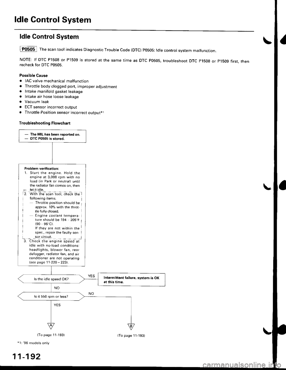
ldle Control System
ldle ControlSystem
lF0505 l Th" """n tool indicates Diagnostic Trouble Code (DTC) PO5O5: tdte controt system malfunction.
NOTE: lf DTC P1508 or P1509 is stored at the same time as DTC P0505, troubleshoot DTC p1508 or p1bog first. thenrecheck for DTC P0505.
Possible Cause
. IAC valve mechanical malfunction
. Throttle body clogged pon, improper adjustment. Intake manifold gasket leakage
. Intake air hose loose leakage
. Vacu um leak
. ECT sensor incorrect output
. Throttle Position sensor incorrect output*r
Troubleshooting Flowchart
The MIL has been reoorted on.DTC P0505 is stored.
Problem verification:1. Start the engine. Hold theeng;ne at 3,000 rpm with noload (jn Park or neutral) untilthe radiator fan comes on, then*r let it idle.t2. with rhe scan toot, ct'eit Ge l
Throttle position should beapprox. 10% with the throttle fully closed.E ngine coolant tempera-ture should be 194 205'F(90 96.Ci.lf they are not within thespec., repair the faulty sen
L._ _9oI9[cr]41 l3. Chec& the engine speed atidle with no-load cond;tionsiheadlights, blower fan, reardefogger, radiator fan, and airconditioner are not operating\see page l1-22O - 223).
Intermittent tailure, system is OKat this time.ls the idle speed OK?
ls it 550 rpm or less?
(To page 11,193)
*1r'96 models only
11-192
(To page ll-193)