Page 693 of 2189
GRADE LOGIC CONTROL SYSTEM
How it works:
The pCM compares actual driving conditions with driving conditions memorized in the PCM, based on the input from the
vehicle speed sensor, the throttle position sensor, the barometoric pressure sensor, the engine coolant temperature sensor,
the brake switch signal, and the shift lever position signal, to control shifting while a vehicle is ascending or descending a
slope, or reducing speed.
SIGNALS OETECTED
O.iving Resi3lence
Judgemenl ot Conirolling Arca
. Ascending mod€
lFuzzy loqicl. Gradual Ascending mode' Ste€p Ascending mode. Oescending mode. Gr.du.l Descending mode. Steep D6cending mode
14-15
Page 694 of 2189

Description
Electronic Control System {cont'dl
Ascending Control
When the PCM determines that the vehicle is climbing a hill in E position, the system oxtends the sngagement area of2nd gear and 3rd gear to prevent ths transmission from fr€quently shifting between 2nd and 3rd gears, and between 3rdand 4th gears, so the vehicle can run smooth and have more power when needed. There are two ascending modes withdifferent 3rd gear driving areas according to the magnitude of a gradient stored in the pCM.
NOTE:
. The PCM memory contains shift schedules between 2nd and 3rd gears, and between 3rd and 4th gears that enable thePCM's fuzzy logic to automatically select the most suitable gear according to the magnitude of a gradient. Fuzzy logic is a form of artificial intelligence that lets computers respond to changing conditions much like a humanmind would,
Dssconding Control
When the PCM determines that the vehicle is going down a hilt in E position, the shift-up speed from 3rd to 4th gearwhen th€ throftle is closed becomes faster than the set speed for flat road driving to widen the 3rd gear driving area.This, in combination with engine braking from the deceleration lock-up, achieves smooth driving when the vehicle isdescending. There are two descending modes with different downshift (4 - 3) schedules according to the magnitude of agradient stored in the PCM. When the vehicle is in 4th gear, and you are decelerating on a gradual hill, or when you areapplying the brakes on a steep hill, the transmission will downshift to 3rd gear. When you accel6rate, the transmission willthen return to 4th gear.
ASCENDING MODEDESCENDING MODE
4TH SHIFTING
L.
F
CHARACTERISIICSCONTROL AREA
ff.1"11", vehicr. 3pe€dff;Tlr., vohicre speed
GRADUAL ASCENOINGCONTROL AREA
Docel6ration Control
When the vehicle goes around a corner. and needs to first decelerate and then accelerate. the rcM sets the data for decelerationcontrol to reduce the number of times the transmission shifts. When the vehicle is decelerating from speeds above 26 mph(41 km/h), the rcM shifts the transmission from 4th to 2nd earlier than normal to cope with upcoming acceleration.
14-16
Page 721 of 2189

I
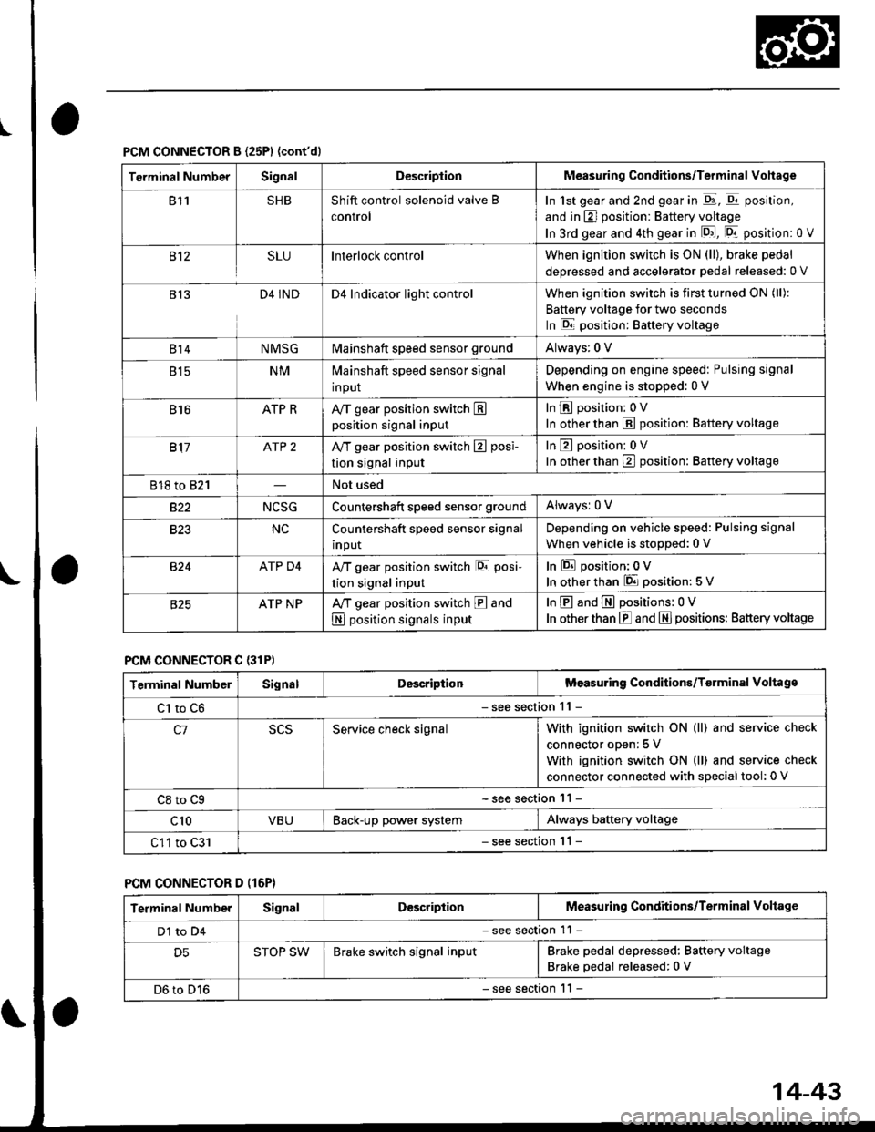
PCM CONNECTOR B {25P1 {cont'dl
Terminal NumberSignalDescriptionMeasuring Conditions/Terminal Vohage
811SHBShift control solenoid valve B
control
In 1st gear and 2nd gear in -q1, q11 position,
and in E] position: Battery voltage
In 3rd gear and 4th gear in lD.J, [Dr- position: 0 V
B't2SLUInterlock controlWhen ignition switch is ON (ll), brake pedal
deoressed and accelerator Dedal released: 0 V
813D4 INDD4 Indicator light controlWhen ignition switch is first turned ON (ll):
Battery voltage for two seconds
In E position: Baftery voltage
B't 4NMSGMainshaft speed sensor groundAlways: 0 V
E tcNMMainshaft speed sensor signal
input
Depending on engine speed: Pulsing signal
When engine is stopped: 0 V
816ATP RAy'T gear position switch Eposition signal input
InE position: 0V
In other than E position: Battery voltage
817ATP 2A/T gear position switch E posi-
tion signal input
InE position: 0V
In orher than E position: Battery voltage
818 to 821Not used
s22NCSGCountershatt speed sensor groundAlwaysr 0 V
B�23NCCountershaft speed sensor signal
input
Depending on vehicle speed: Pulsing signal
When vehicle is stopped: 0 V
B�24ATP D4Ay'T gear position switch lor posi-
tion signal input
InEposition:0V
In other than 6 position: 5 V
ATP NPA,/T gear position switch E and
N position signals input
InE and E positions: 0V
In otherthan E and N] positions: Battery voltage
PCM CONNECTOR C {31P)
Terminal NumberSignalDescriptionMeasuring Conditions/Terminal Voltage
Cl to C6- see section 11 -
c1Service check signalWith ignition switch ON (ll) and service check
connector oDen; 5 V
With ignition switch ON (ll) and service check
connector connected with sDecial tool: 0 V
C8 to Cg- see section 11 -
c10VBUBack-up power systemAlways battery voltage
C11 to C31- see section '11 -
PCM CONNECTOR D (16P}
Terminal NumberSignalDescriptionMeasuring Conditions/Terminal Voltage
Dl to D4- see section 11 -
D5STOP SWBrake switch signal inputBrake pedal depressed: Battery voltage
Brake pedal released: 0 V
D6 to D16- see section 1 l -
14-43
Page 724 of 2189

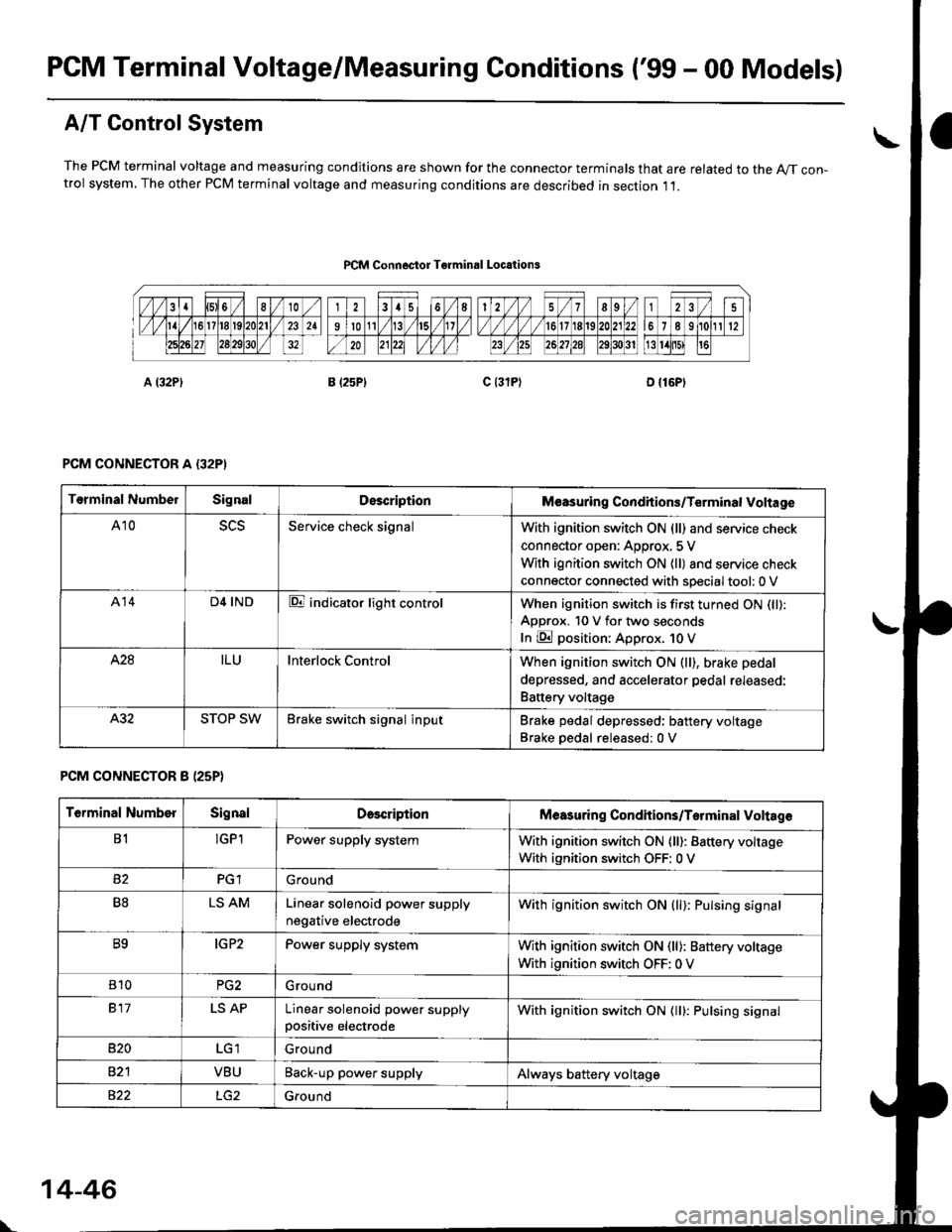
PCM Terminal Voltage/Measuring Conditions ('99 - 00 Models)
A/T Control System
The PCM terminal voltage and measuring condjtions are shown for the connector terminals that are related to the A//T con-trol system, The other PCM terminal voltage and measuring conditions are described in section ,11.
PCM Connoctor Tgrminrl Locations
PCM CONNECTOR A {32PI
PCM CONNECTOR 8 (25P}
Terminal NumbelSignalDescriptionM€asuring Conditions/Terminal Voltage
A105L5Service check signalWith ignition switch ON (ll) and service check
connector open: Approx, 5 V
With ignition switch ON (ll) and service check
connector connected with sDecial tool: 0 V
A14D4 INDE indicator light controlWhen ignition switch is first turned ON (ll):
ApDrox. 10 V for two seconds
In E position: Approx. 1O V
428ILUInterlock ControlWhen ignition switch ON (ll), brake pedal
depressed, and accelerator pedal rereaseo:
Battery voltage
A.32STOP SWBrake switch signal inputBrake pedal depressed: battery voltage
Brake oedal released:0 V
Terminal NumberSignalDescdptionMeasuring Condhions/Torminal Voltag6
B1!GP1Power supply systemWith ignition switch ON (ll): Battery voltage
With ignition switch OFF: 0 V
PGlGround
B8LS AMLinear solenoid power supply
negative electrode
With ignition switch ON (ll): Pulsing signal
B9IG P2Power supply systemWith ignition switch ON (ll): Baftery voltage
With ignition switch OFF: 0 V
810PG2G rou nd
917LS APLinear solenoid power supplypositive electrode
With ignition switch ON (ll): Pulsing signal
B�20Ground
VBUBack-up power supplyAlways battery voltage
822Ground
\
14-46
Page 731 of 2189
SYmPtom
E indicator light does not come on tor two seconds after ignition
switch is first turned ON {ll}.
E indicator light is on constantly (not blinking) whenever the ignition
switch is ON (ll).
Shift lever cannot be moved from @ position with the brake pedal
depressed.
Inspection Ref. Page
11-16
14-78
Inspection't4-79
lf the self-diagnostic l-d indicator light does not blink, perform an inspection according to the table below.
NOTE: lf a customer describes the symptom for code Pl706 {6), it will be necessary to recreate the symptom by test-driv-
ing, then recheck the DTC.
14-53
Page 733 of 2189
E i"dl.r." fiSh, 1."""". y{*fu
Reference page
14- 101
lE indicator light does not come on for two seconds after ignition switch is first turned oN (ll).14-102
Shift lever cannot be moved from E position with the brake pedal deprsssed'14-104
lf the self-diagnostic E indicator light does not blink and following symptoms appear, perform an inspection according to
the table below.
14-55
Page 757 of 2189
Troubleshooting Flowchart - Brake Switch Signal
Symptom
Shift lever cannol b€ moved f.om
B pGition with the brako podrl
depr8sed.
PCM CONNECTORS
Check Brako Light Operation:Deoress the brake pedal.
Rop.ir faulty braks switch cilcuit
lsos soction 231.Are the brake lights ON?
Measure SToP SW Vohag€:1. Turn the ignition switch OFF.2. Disconnect the A l32P) and D
{l6P) connectors from thoPCM.3. Measure the voltage belweenthe D5 and A9 or A22 termi-nals with the brake Pedaldepressod.
Rap.i. opon in the wira bctn oentha 05 terminal and tho btrkclwitdr.ls there battery voltage?
. Brake switch 3ign.l is OK.. Ch6ck lor looao PCM oonnoctors.It nocassary, aubctilute a known-good PCM and r€check.. Inspoct the brake switch circuit
{s6e section 231.
Wire side of lemale terminals
Page 782 of 2189
ElectricalTroubleshooting ('99 - 00 Modelsl
Troubleshooting Flowchart - Brake Switch Signal
PCM CONNECTORS
Wire side of female terminals
Shift lever cannot be moved tromE position with tho b.ake pedaldepressod.
Check Brake Light Operation:Depress the brake pedal.
Repair t ulty brake switch circuit{see s€ction 23}.Are the brake llghts ON?
Mea3ure STOP SW Vohage:1. Turn the ignition switch OFF.2. Disconnect the A (32P) and B{25P} connectors from thePCM,3. Measure the voltage betweenthe A32 and 820 or 822 termi-nals with the brake pedal
depressed.
Repair open in the wire betwsenthe A32 terminal rnd tho brrk6switch.
ls there battery voltage?
. Brak€ switch sign.l is OK.. Check for loose terminal fil inlhe PCM conn€ctors. lf neces-sary. substitute a known-goodPICM and recheck.. InsDect the breke 3witch circuitlsee section 231.
B {25P)
\
14-104