1999 HONDA CIVIC wire
[x] Cancel search: wirePage 1442 of 2189
Troubleshooting
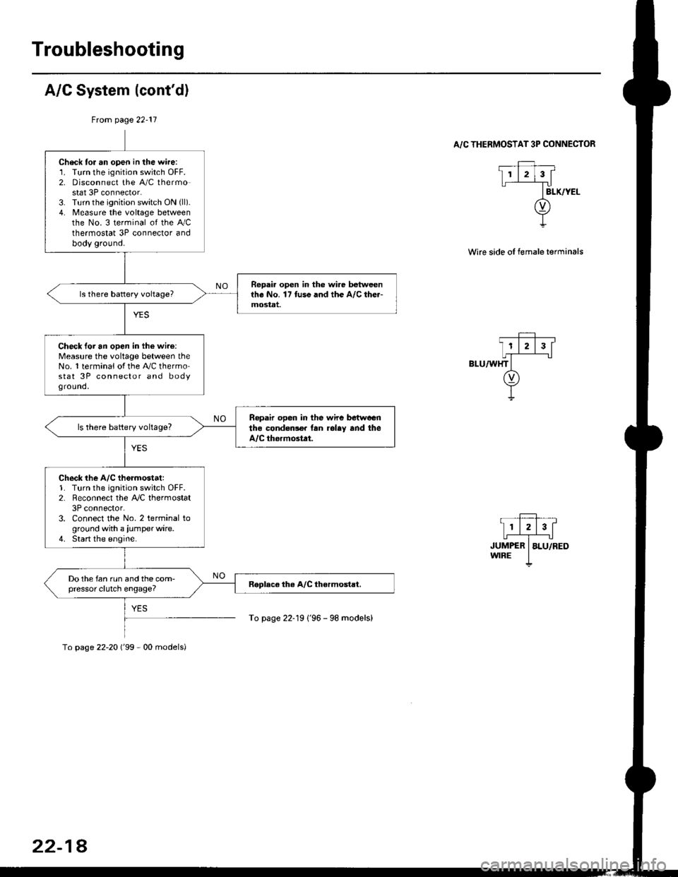
A/C System (cont'd)
From page 22-11
. _Ff,, __
I11213[
,r,il*"-T",-.r-'..owrRE I
To page 22-19 1'96 - 98 models)
A/C THERMOSTAT 3P CONNECTOR
Wire side oI female terminals
Check tor an open in the wire:1. Turn the ignition switch OFF.2. Disconnect the A/C thermostat 3P connector.3. Turn the ignition switch ON (ll).
4. Measure the voltage betweenthe No. 3 terminal of the Ay'Cthermostat 3P connector andbody ground.
Repai. open in the wire betweentho No. 17 tuso and the A/C the.-mostat.
Check loi an open in the wi.e:Measure the voltage between theNo. 1 terminal of the A,/C thermostat 3P connector and bodyground,
Ropair open in the wire betwoenthe condedlo. lan rolay and theA/C thormostat.
ls there battery voltage?
Check the A/C th6rmostat:1. Turn the ignition switch OFF.2. Reconnect the A,/C thermostat3P connector.3. Connect the No. 2 terminal toground with a iumperwire.4. Start the engine.
Do the fan run and the com-pressor clutch engage?
To page 22-20 ('99 - 00 models)
22-18
Page 1443 of 2189
Ftom page 22 18
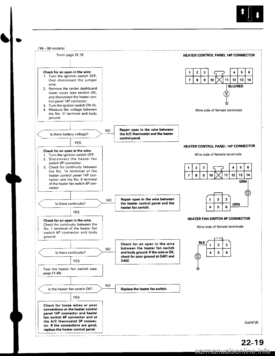
Check tor an open in the wire:1. Turn the ignition switch OFF,then disconnect the iu mper
2. Remove the center dashboardlower cover lsee section 20),
and disconnect the heater con'
trol panel 14P connector.
3. Turn the ignition switch ON (ll).
4. Measure the voltage betweenthe No. 11 terminal and bodyground.
Repair op6n in the wire bstween
the A/C th€rmostat and th6 hoater
control panel.
Check lor an open in the wire:
1. Turn the ignition switch OFF.2. Disconnect the heater Ian
switch 6P connector,3. Check for continuity between
the No. 14 terminal of theheater control panel 14P con_nector and the No.6 terminalof the heater fan switch 6P con-nector.
Repair open in the wiro betweGnthe heal.r control Panel and theheater fan switch.
Check for an open in thG wire:Check for continuity between theNo. 1 terminal of the heater lanswatch 6P connector and bodYground.
Chock tor an open in tho wir€
between the heater lan switch
and body ground. lf the wire is OK,check for poor ground at G401 sndG402.
ls there continu;ty?
ReDlace the heater tan switch.ls the heater fan switch OK?
Check for loose wiaes or poor
connections at the heater controloanel 14P connoctor and hoetertan 3witch 5P conn€clor and atthe A/C thermostet 3P connec-tor. ll the connections are good,
raplace the heator control Panel.
r'oA - qe m^.lalal
HEATER CONTROL PANEL lilP CONNECTOR
tra6
7II'o lx't1121314
BLU/RED
Wire side of female terminals
HEATER CONTROL PANEL 1'P CONNECTOR
Wire side of female terrninals
HEATER FAN SW]TCH 6P CONNECTOR
Wire side of female terminals
(cont'd)
12;--?45
7I10X'll121314
GRN
123
a56GRN
22-19
Page 1444 of 2189
Troubleshooting
('99 00 models)
From page 22 18
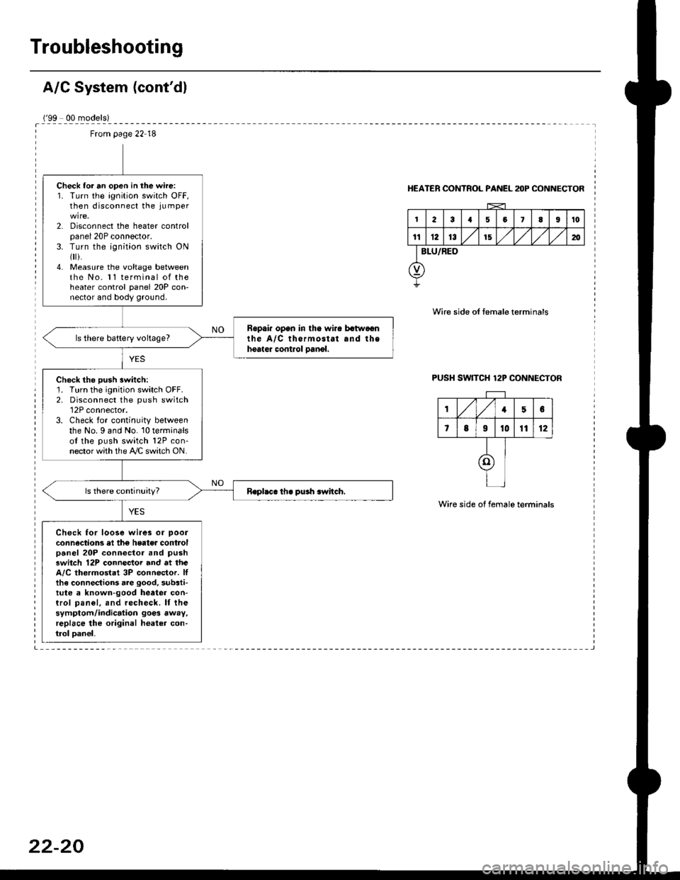
Check lor an open in the wire:1. Turn the ignition switch OFF,then disconnect the ju mper
2. Disconnect the heater controlpanel 20P connector.3. Turn the ;gnition switch ON{
i.4. Measure the voltage betweenthe No. 11 terminal of theheater control panel 20P con-nector and body ground.
Ropai. opan in tho wira batwaonthe A/C thermostat and thehoater control oanol.ls there battery voltage?
Check the push switch:1. Turn the ignition switch OFF.2. Disconnect the push switch12P connector.3. Check for continuity betweenthe No. I and No. 10 terminalsof the push switch 12P con-nector with the A/C switch ON.
Check for loose wi.es or poor
connections el the hgater controlpanel 20P connector and pushswitch 12P connector and at theA/C thermostat 3P connector. Ittha connections are good, substi-tute a known-good heatea con-trol pan€|, and recheck. lf thesymptom/indication goe3 away,replace lhe original healer con-trol oan€|,
HEATER CONTROL PANEL anP CONNECTOR
Wire side of temale terminals
PUSH SW]TCH 12P CONNECTOR
Wire side of female terminals
,/1,/156
7819t01112
I
I
I
Page 1452 of 2189
Evaporator
1.
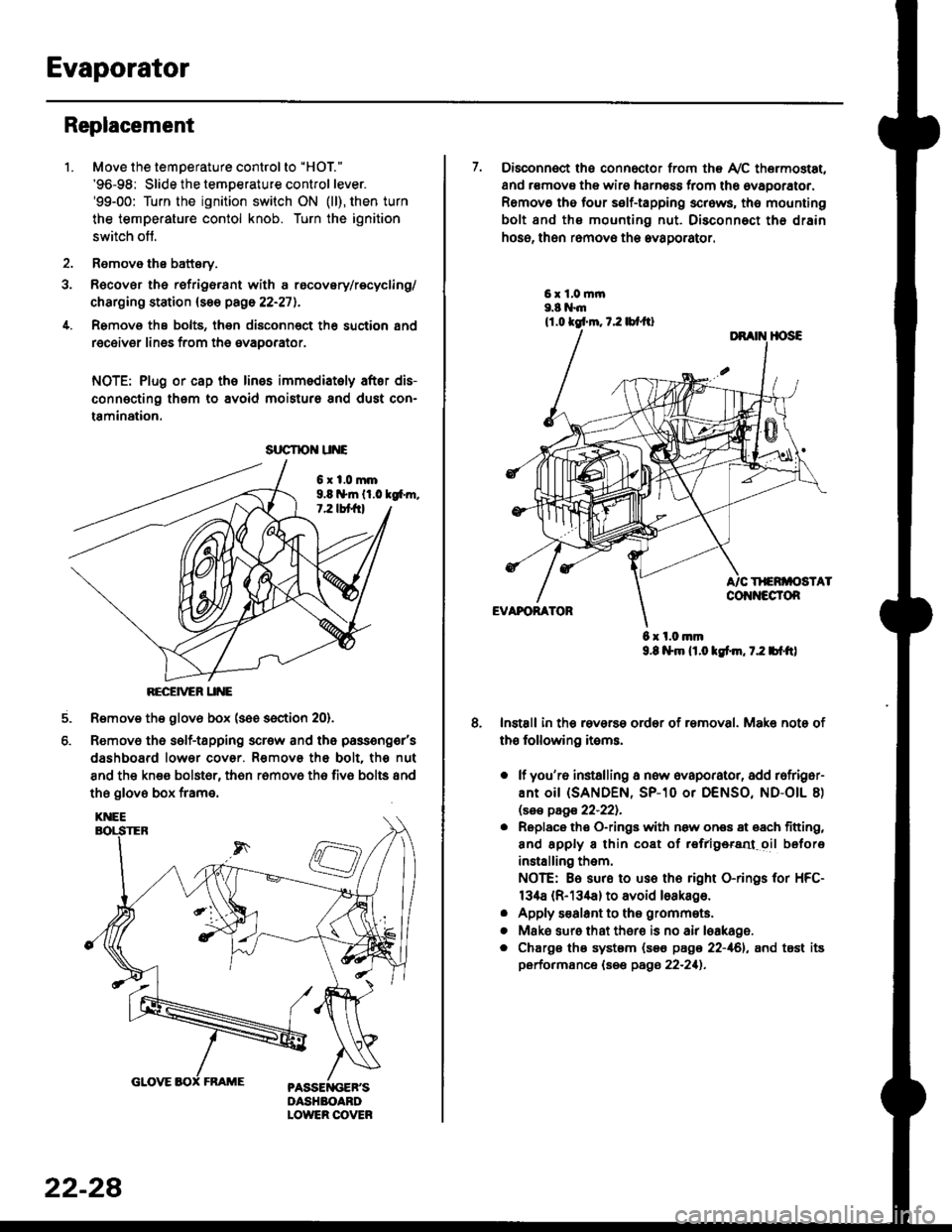
Replacement
4.
Move the temperature control to "HOl"
'96-98: Slide the temoerature control lever.'99-00: Turn the ignition switch ON (ll), then turn
the temperature contol knob. Turn the ignition
switch off.
Remove the battsry.
Rgcover the refrigerant with a rocovery/recycling/
charging station (see page 22-271.
Remove the bolts, then disconnect th6 suction 8nd
receiver lines from th6 evaoorator.
NOTE: Plug or cap the lines imm€diatoly after dis-
connecting them to avoid moisture and dust con-
tamination.
6xl.0mm9.8 n*ln ll.0 tg6m.7.2 lbt frl
RECEiVER UNE
Remove the glov6 box (see section 20).
Removo the self-tapping scr€w and the passeng€r's
dashboard lower cover. Removs the bolt. the nut
8nd the kn€e bolst6r, th6n r6mov6 th6 fiv6 bolts and
the glove box frame.
6.
srrcrrc u E
22-28
7. Disconnect the connector from th€ Ay'C thermostat,
and r€movs the wire harness from the ovaporator.
Remov6 tho four self-tapping screws, tho mounting
bolt and ths mounting nut. Disconnect th€ drain
hose, then remov€ th6 avagorator.
6 x l.0.nm9.8 l$m lt.o ldm, 7.2 bl.tt)
Install in the reverse order of removal. Make note of
th€ following items.
o lf you'r6 installing a new evaporator, add rofriger-
ANt OiI {SANDEN, SP-10 Or DENSO, ND-OIL 8)
lsas page 22-221.
. Replace the O-rings with now ones 8t 68ch titting,
and apply 8 thin coat of r€frlgersd oil before
installing them.
NOTE: Be sure to use the right O-rings for HFC-
134a (R-134a) to avoid loakago.
. Apply s€alant to tha grommets.
. Mske sure that ther€ is no air leakage.
. Chargs ths system {s€€ page 22-161, and tost its
performance (see pags 22-211.
Page 1459 of 2189
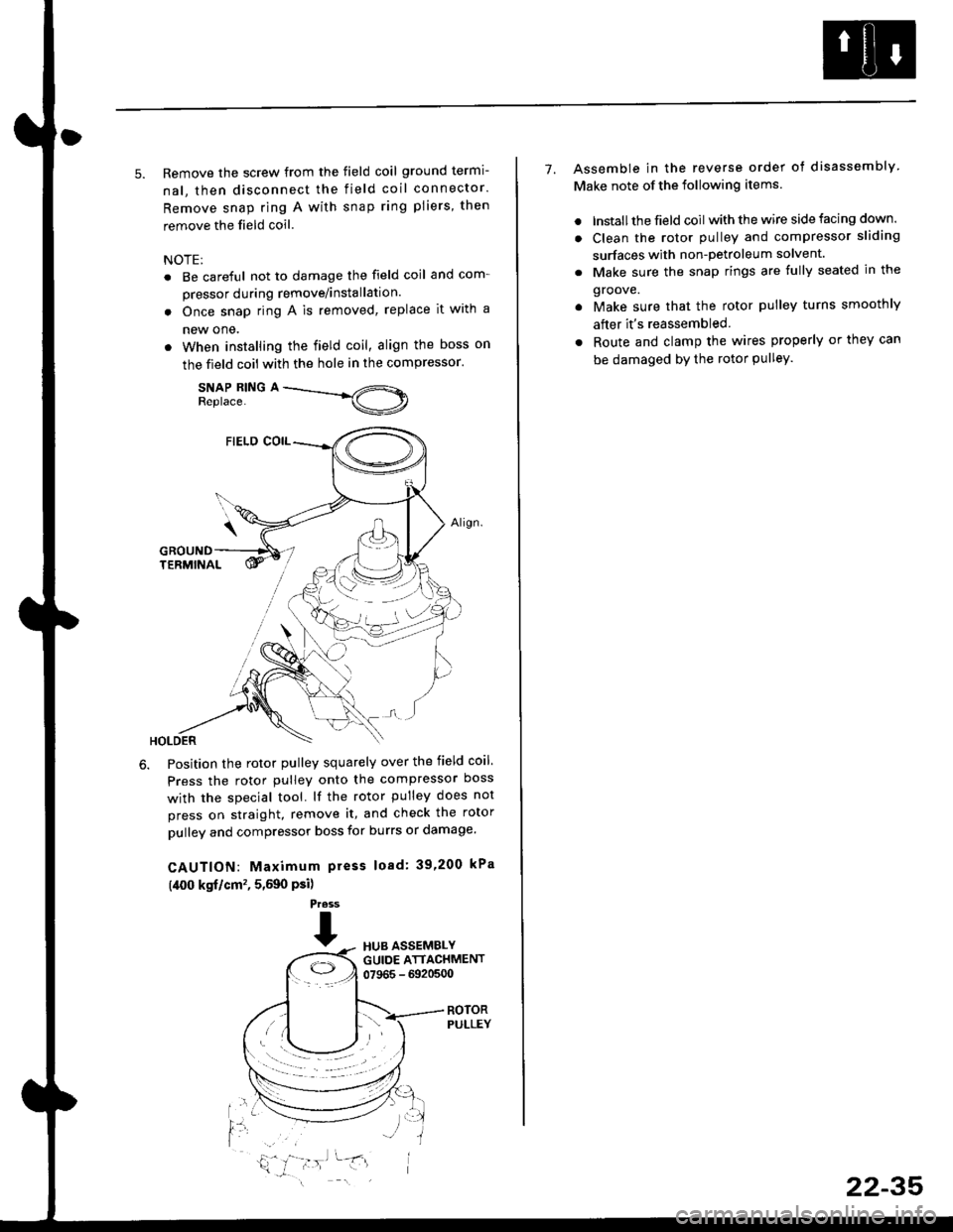
5. Remove the screw from the field coil ground termi-
nal, then disconnect the field coil connector.
Remove snap ring A with snap ring pliers, then
remove the field coil
NOTE:
. Be careful not to damage the field coil and com-
pressor during remove/installation.
. Once snap ring A is removed, replace it with a
new one.
. When installing the field coil, align the boss on
the field coil with the hole in the compressor.
SNAP RING AReplace.
Position the rotor pulley squarely over the field coil.
Press the rotor pulley onto the compressor boss
with the special tool. lf the rotor pulley does not
press on straight, remove it, and check the rotor
pulley and compressor boss for burrs or damage.
CAUTION: Maximum press load: 39,200 kPa
(,[00 kgf/cm'�, 5,590 Psi)
Press
THUB ASSEMBLYGUIDE ATTACHMENT07965 - 6920500
ROTORPULLEY
t'l
i,'
7. Assemble in the reverse order of disassembly
Make note of the following items.
. lnstall the field coil with the wire side facing down.
. Clean the rotor pulley and compressor sliding
surfaces with non-petroleum solvent.
. Make sure the snap rings are fully seated in the
groove.
. Make sure that the rotor pulley turns smoothly
after it's reassembled
. Route and clamp the wires properly or they can
be damaged bY the rotor Pulley.
22-35
Page 1466 of 2189
Compressor (DENSO)
Clutch Overhaul (cont'd)
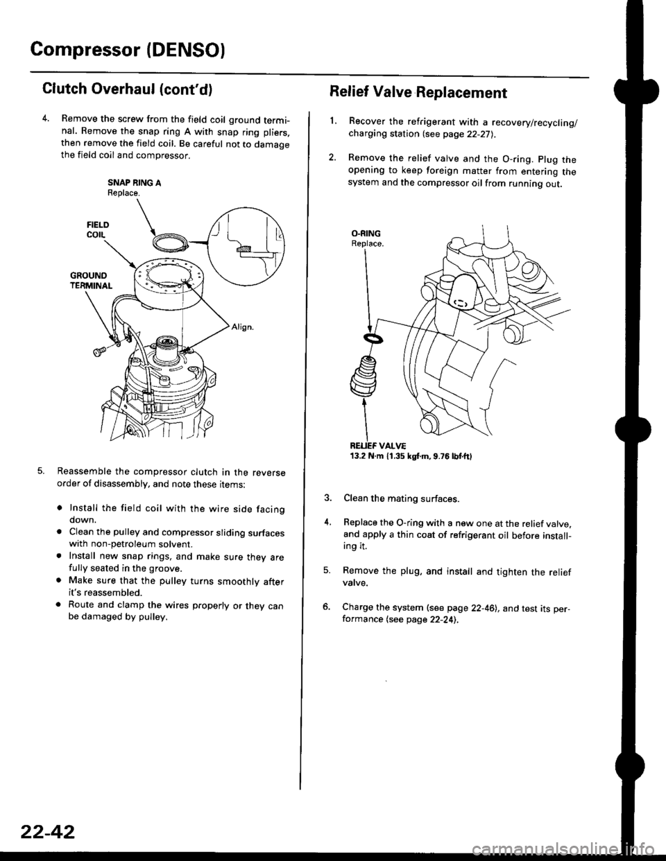
Remove the screw from the field coil ground termi-nal. Remove the snap ring A with snap ring pliers.
then remove the field coil. Be careful not to damaoethe field coil and compressor.
SNAP NING AReplace.
Reassemble the compressor clutch in the reverseorder of disassembly, and note these rrems:
o Install the field coil with the wire side facingdown.
a Clean the pulley and compressor sliding surfaceswith non-petroleum solvent.. Install new snap rings, and make sure thev arefully seated in the groove.
. Make sure that the pulley turns smoothly afterit's reassembled.
. Route and clamp the wires p.operly or they canbe damaged by pulley.
FIELOcorL
22-42
13.2 N.m 11.35 kgt m,9.76lbtttl
Relief Valve Replacement
L
4.
Recover the refrigerant with a recovery/recycling/charging station {see page 22-27),
Remove the relief valve and the O-ring. plug theopening to keep foreign matter from entering thesystem and the compressor oilfrom running out.
Clean the mating surfaces.
Replace the O-ring with a new one at the relief valve.and apply a thin coat of refrigerant oil before install-ing it.
Remove the plug, and install and tighten the reliefvatve.
Charge the system (see page 22-46), and test its per-formance (see page 22-24),
Page 1468 of 2189
Condenser
Replacement
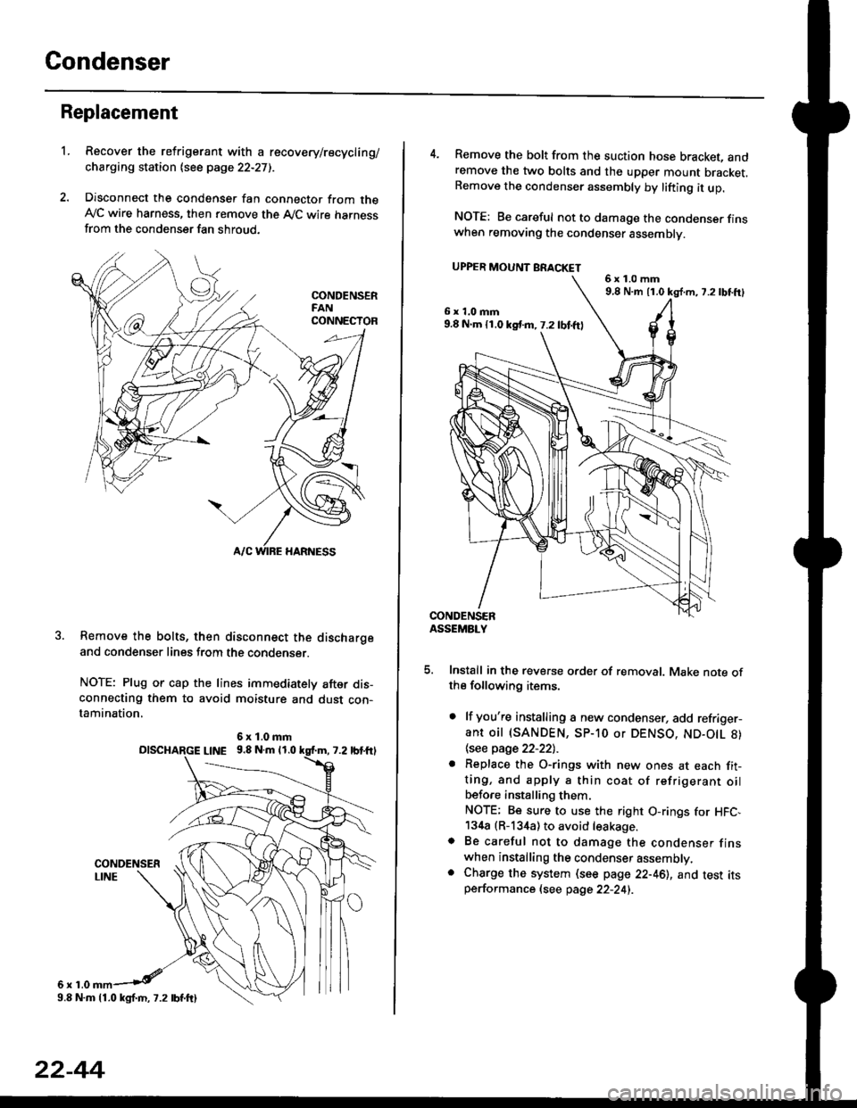
1.Recover the refrigerant with a recovery/recycling/
charging station lsee page 22-271.
Disconnect the condenser fan connector from theAy'C wire harness, then remove the A,/C wire harnessfrom the condenser fan shroud.
Remove the bolts, then disconnect the dischargeand condenser lines from the condenser.
NOTE: Plug or cap the lines immediately after dis-connecting them to avoid moisture and dust con-tamination,
6r1.0
6x1.0mmolscHARGE L|NE 9.8 N.m 11.0
9.8 N.m 11.0 kgl.m, 7.2 lbf.ftl
22-44
4. Remove the bolt from the suction hose bracket, andremove the two bolts and the upper mount bracket.Remove the condenser assembly by lifting it up.
NOTE: Be careful not to damage the condenser finswhen removing the condenser assembly.
UPPER MOUNT BRACKET
5. Install in the reverse order of removal. Make note ofthe following items.
. lf you're installing a new condenser, add refriger-ant oil (SANDEN, SP-10 or DENSO, ND-O|L 8)
\see page 22-22l.-
. Replace the O-rings with new ones at each fit-ting, and apply a thin coat of refrigerant oilbefo.e installing them.
NOTE; Be sure to use the right O-rings for HFC,134a (R-134a) to avoid leakage.o Be careful not to damage the condenser finswhen installing the condenser assembly.. Charge the system (see page 22-46), and test itsperformance (see page 22-24i.
6x1.0mm9,8 N.m 11.0 kg{.m, 7.2lbtft}
6x1.0mm9.8 N.m 11.0 kst m, 7.2 lbf.ftl
Page 1471 of 2189

l'f .
Electrical
Special Toofs .,....................,23-2
Troubleshooting
Tips and Precautions ..............,.................... . 23-3
Five-step Troubleshooting .............. ......... . . 23-5
wire color codes ..........,23-5
Schematic Symbols ........,................... . . .. .... 23-6
Relay and Control Unit Locations
Engine Compartment ...,..................... ... .. . 23'7
Dashboard ......................23-8
Dashboard/Door ......... 23-12*Airbags ................. ....... Section 24
Air Conditioning ......... Section 21
Aftelnator ..........."""" """ 23-112
Anti-lock Brake System {ABS) Section 19*A/T Gear Position Indicator .....................,. .... ... 23-149
Automatic Transmission Svstem .... . ....... Section 14
Batterv ......... . . . ... ...... .......23-91
Blower controls .. . ... Section 2l
Charging System ....'...........23'112
Connector ldentilication and Wire Harness
Routing .................. ......23'13
Cruise Control ............,........23-240
Dash Lights Brightness Controller ............. ....... 23-180
Fan controfs "" 23'126
Fuel PumD ........ . ........ section 11
Fuses/Refay ...............,..,,.. 23'62
PGM-FI Control System ......................,....... Section 1 1
*Gauges
Circuit Diagram ....,.,.......23-131
Fuef Gauge ...........'.'.......23-142
Gauge/lndicator .. . .. 23-129
Ground Distribution .. . 23-75
Heatei controls .. . ..... Section 21*Horn................. ...............23-196
*tgnition Switch ....................23-89
lgnition System .......,.... 23-102
*lntegrated Control Unit ....................................... 23-156
fnterlock System ,........ . . , ,23-144
Lighting System . . . .. ......... 23-161
Lights, Exterior
Back-up Lights ..'............23'171
Brake Lights .................. 23'174
Daytime Bunning Lights (Canadal ............... 23'166
Front Parking Lights ......,................ .'. .......... 23-167
Front Turn Signal Lights .......... . . ............ ..,.23-167
Headtights ....".'....-... ..... 23'167
High Mount Brake Light ...................... ... .23'179
License Plate Lights ...... 23'176
Taitfights ................ .......23'171
lnterior Lights ..-.......,, . 23-142
Moonroof ..,.................,........ 23-235
Power Distribution ....... . . .23-61
Power Door Locks .......,,,. .23'251
Power Mirrors ,..............,.,...23'206
Power Relays ....... . ...... . . .. 23-86
Power Windows ............,,....23-220
Rear Window Defogger .......................... . . ... . . 23-2OO
Spark Plugs . ..... . ........ .....23-111
Slarting System ................23-93*stereo Sound Svstem ,................. ..... ... . ... ,.,.,,23'147'Supplemental Restraint System (SRS) ... . Section 24
Turn Signal/Hazard Flasher System .......'.'....-... 23-173
*Undel-dash Fuse/Relay Box ............,.................. 23-85
vehicfe soeed sensor (VSSI """" ""' 23-140+Wipers/Washers .........,.,.,...23-214
NOTE: Unless otherwise specified, references to auto-
matic transmission (Mf) in this section include the CVT.