1999 HONDA CIVIC shift lever
[x] Cancel search: shift leverPage 871 of 2189

Continuously Variable Transmission (CVTI
Special Tools ................ 14-194
Description .................... 14-195
Clutches/Reverse Brake/Planetary
Gear/Pulleys .......... 14-198
power Flow ..............,..... 14-200
Electronic Control SYstem(,96 - 98 Modets) ......14-203
Electronic Control System
('99 - oo Models) " 14-205
Hydraulic Control '....... 14-208
Hydraulic Flow .'..-.....'... '14-212
Park Mechanism .....-...'.' 14-222
Eleqtrical Systom
Component Locations'96 - 98 Models """"""' 14-224,99 - 00 Modets ............. 14-225
TCM Circuit Diagram ('96 - 98 Models) ............. 14-226
TCM Terminal Voltage/Measuring Condiiions ('96 - 98 Models) '.... 14-228
PcM Circuit Oiaqram{A/T Control System: '99 - 00 Models} ...--.... 14-230
PCM Terminal Voltage/Measuring Conditions('99 - 00 Models)
A/4 Control System .'.'...14-232
Troubleshooting Procedures ... . .... .....',........."' '14-234
Symptom-to-ComPonent Chart
Electrical System - '96 - 98 Models ......'..... '14-234
Electrical System -'99 - 00 Models ..'....-..-. '11-210
Electrical Troubleshooting
Troubleshooting Flowcharts('96 - 98 Models) """'11-242
Troubleshooting Flowchart
('99 - 0O Modets) ...... 14-265
Linear Solenoids/lnhibitor Solenoid
Test ......................... . ...... 14-29f
Drive Pulley/Driven Pulley/Secondary Gear
Shaft Speed Sensors
Replacement .........'...... .14-292
Start Clutch Control
Start Clutch Calibration Procedure ....... ....,. 14-293
Hydraulic SYstem
Symptom-to-ComPonent Chart
Hydraulic System '.'.......14-294
Road Test ............................ 14-296
Stall Speed
Test......................... ...... 14-294
Fluid Level
Checking/Changing ....... 14-299
Pressure Testing ................. 14-300
Lower Valve BodY AssemblY
Replacement ..........,... 14-302
ATF Filter
Removal/lnstallation ..... 14-303
Transmission
Transmission
Removal ........... . 14-304
lllustrated Index
Transmission/Lower Valve BodY
Assembly ................. 14-308
Transmission Housing/Flywheel Housing ... 14-310
End Cover/f ntermediate Housing ..........'.'.... 14-312
Transmission Housing/Lower Valve Body Assembly
Removal ..........'.... .. " 14-314
Transmission Housing/Flywhesl Housing
Removal ................. ........ 1+316
End Cover/lntermediate Housing
14-318Removal .........,...............
Manual Valve Body
Disassembly/lnspection/Reassemblv .'.'.'..... 1 4-320
Forward Clutch
lltustrated Index ........................................ 14-321
Disassemblv .................. 14-322
Reassemblv , ,, . ',','......14-324
Secondary Gear Shaft
25 x 35 mm Thrust Shim Selection ..'.'....-... 14-324
Differential
lllustrated lndex ...,.....................,.,...-.-.-...'... 14-329
Backlash Inspection .-....14-329
Bearing Replacement ......'........'....'... ....'... 14-330
Differential Carrier Replacement ........'........ 14-330
Oil Seal Removal ........... 14-331
Oil Seal Installation/Side Clearance ....... . . 14-331
Flywheel Housing Input Shaft Oil Seal
Replacement .....,.... ...'.'.. 14-333
Transmission Housing Bearings
Driven Pulley Shaft Bearing
Replacenient ...................'. . ...................'.. 14-334
Secondary Gear Shaft Bearing
Reolacbment ...................... . .......... . ........ 14-335
Flywheel Housing Beating
Secondary Gear Shaft BearingReo1acement..................,........................... 14-335
Ring Gear Bearing
Replacement......... ........ 14-336
Control Shaft Assembly
Removal/lnstallation ....................'........... 14-336
Transmission
Reassembly .................. 14-338
Flywheel/Drive Plate .. . ...... . ...... ... . ....-.....'.'...14-341
Transmission
lnstalation ..................... 14-348
Cooler Flushing .'......... 14-352
shift cable
Removal/lnstallation....'........." """ 14-354
Adjustment .......'........ 14-355
Shift Lever ........................,. 14'356
Shift Indicator Panel
Adjustment ................ 14-357
ATF Cooler/Hoses
lnsta llation ......,,...... .... 14-357
Page 874 of 2189

Description
(cont'd)
Gear Sel€stion
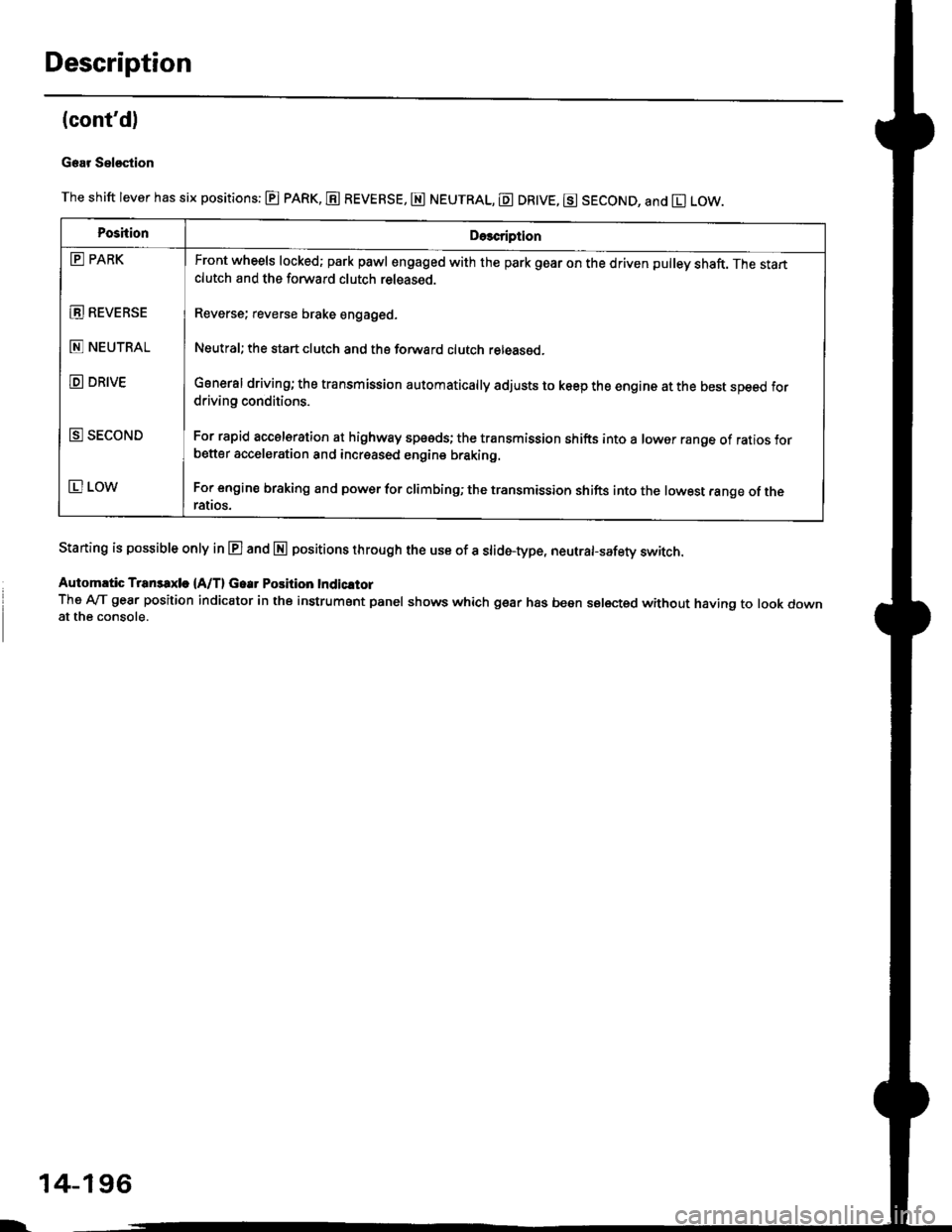
The shift lever has six positions: @ pARK, E REVERSE, E NEUTRAL, E DR|VE, g SECOND, and El LOW.
Staning is possible only in E and E positions through the use of a slid6-type, neutrafsafety switch.
Automrtic Transaxle {A/T} Gear Position Indicltor
The A-lT gear position indicator in the instrument panel shows which gear has been selected without having to look downat the console.
PoshionDe3cription
E PARK
E REVEBSE
E NEUTRAL
D DRIVE
E SECOND
E LOW
Front wheels locked; park pawl engaged with the park gear on the driven pulley shaft. The startclutch and the forward clutch released.
Reverse; reverse brake engaged.
Neutral; the start clutch and the forward clutch released.
General driving; the transmission automatically adjusts to keep the engine at the best speed fordriving conditions.
For rapid accelsration at highway speeds; the transmission shifts into a lower range of ratios forbetter acceleration and increased engine braking.
For engine braking and power for climbinO; the transmission shifts into the lowest range of theralros.
l-
14-196
Page 884 of 2189

Description
Electronic Control System ('99 - 00 Modelsl (cont'dl
Grade Logic Control System
How it works:
The PcM compares actual driving conditions with memorized driving conditions. based on the input from the vehiclespeed sensor, the throttle position sensor, the manifold absolute pressure sensor, the engine coolant temperature sensor,the brake switch signal, and the shift lever position signal, to control shifting while the vehicle is ascending or descendinga slope.
Ascending Control
When the PCM determines that the vehicle is climbing a hill in E position, the system selects the most suitable shiftschedule (pulley ratio) according to the magnitude of a gradient. so the vehicle can run smooth and have more powerwhen needed. There are three ascending modes with different shift schedules according to the magnitude ot a gradient inthe PCM.
Descending Control
when the PCM determines that the vehicle is going down a hill in E position. the system selects the most suitable shiftschedule (pulley ratio) according to the magnitude of a gradient. This, in combinstion with engine braking, achievessmooth driving when the vehicle is descending, There are three descending modes with different shift schedules accord-ing to the magnitude of a gradient in the PCM.
L
14-206
Page 889 of 2189

Shift Valve BodY
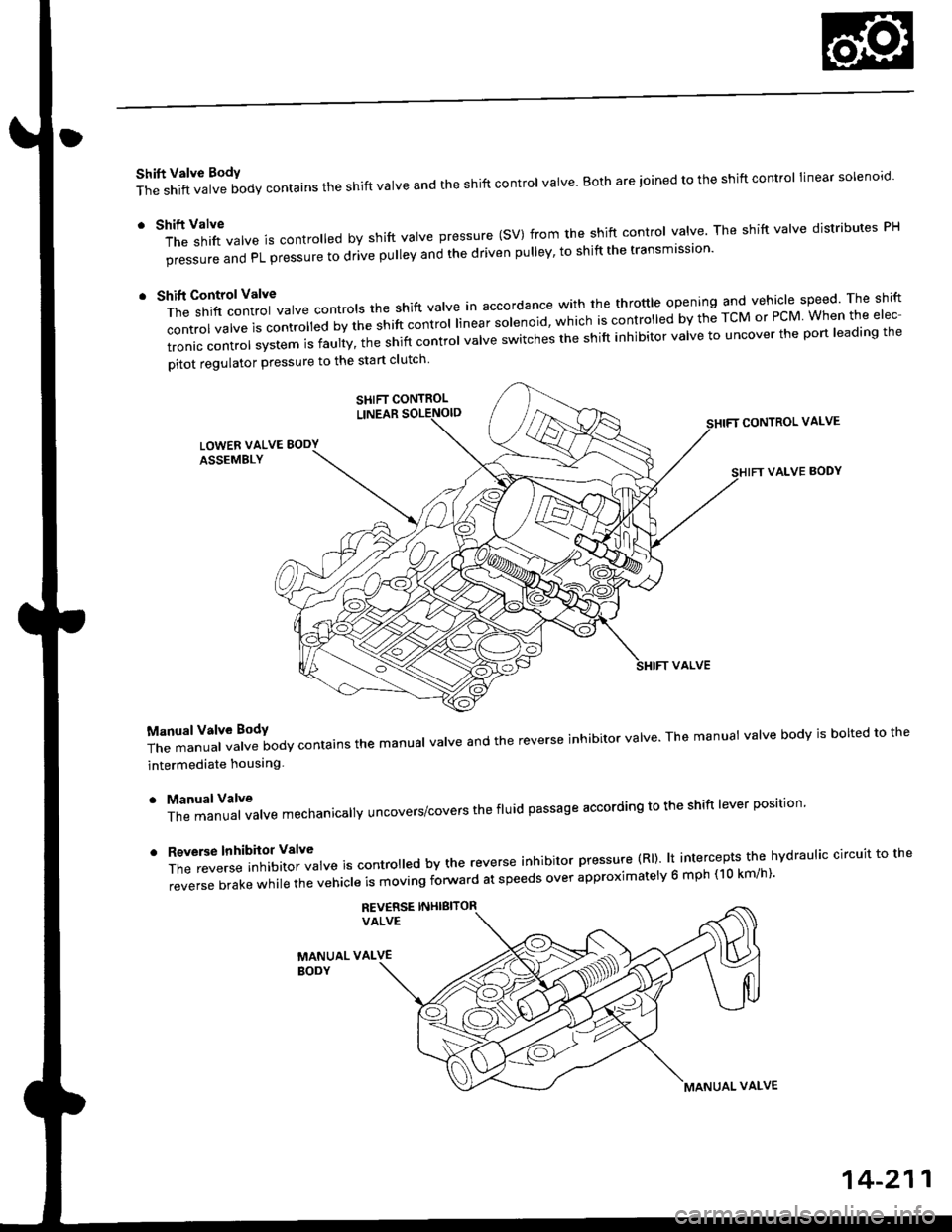
The shift valve body contains the shift valve and the shift control valve. Both are ioined to the shift control linear solenoro.
r tl'ft1il1rf"","" is controred by shift varve pressure (sV) from the shift contror varve. The shift varve distributes pH
pi""aur" "nO PL pressure to drive pulley and the driven pulley' to shift the transmission'
t t*"rilf:::lr';ivarve contrors the shift varve in accordance with the throttre opening and vehicle speed rhe shift
control valve is convorr"o uv ti" "iirt "ontrol linear solenoid, which is controlled by the TcM or PcM When the elec-
tronic control system is faulty, t;; snift controt uutue "witches the shift inhibitor valve to uncover the port leading the
pitot regulator pressure to the start clutch
CONTROL VALVE
VALVE BODY
T;J:"i"""1ff"t""ilody contains the manuar varve and the reverse inhibitor varve. The manuat varve bodv is borted to the
intermediate houslng
. ManualValve
The manual valve mechanicallY uncovers/covers the fluid passage according to the shift lever position'
'
ff:e;;;.'::'?Xftl::T",* is contro ed by the reverse inhibitor pressure (Rl). lt intercepts the hvdraulic circuit to the
reverse brake while the vehicle is moving forward at speeds over approximatelv 6 mph (10 km/h)'
REV€RSE INHIBITORVALVE
MANUAL VALVEBODY
SHIFT CONTROL
MANUAL VALVE
14-211
Page 921 of 2189

Electrical Troubleshooting ('96 - 9g Models)
Troubleshooting Flowchart - A/T Gear position Switch (Short)
NOTE: Record all freeze data before you troubleshoot.
Posrible Cause
. Short in A/T go.r positionswitch wire. Faulty A/T g€ar polition switch
NOTE: Code P1705(5) is caused whenthe TCM receives two gear positionInputs at the same time.
TCM CONNECTOR A {26P}
Wire side of female terminals
To page 14-245
. OBD ll Scan Tool indicates CodeP1705.. Seif-diagnosis @ indicator lightblinksfive times.
Obsorve the A/T gear positionindicetor:1. Turn the ignition switch ON1[).2. Observe tho Ay'T gear positionindicator, and shift to eachposition separately.
Th6 lyrtcm i3 OK at thi. tima.Check the wi.s hamels for drm.ag9.
Do any jndicators stay on when thesh;ft lever is not in that position?
Measure ATP R Vohage:1. Shift to all positions other thanE.2. Measure the voltage betweenthe 411 and A13 or A26 termi-nats.
Check for sho.t in tho wireb€twoon the Al1 t rminaland th6A/l ge.r polhion switch or A/Tgear position indicstor. lf wilo isOK check for loos6 TCM conncc-tora. It nocassery, subrtitute aknown-good TCM and r€chsck.
ls there approx. 10 V?
Measure ATP NP Volt.ge:1. Shift to all positions otherthan @ or @.2. Measure the voltage betweenthe A10 and 413 or 426 termi-nals,Ch.ck tor 3hort in th€ wircb€twe€n thc Al0 termin.l andthe A/T 96r. porition indicrtor,or a short in the wilea b?twecntho A/T gerr porition indic.to.and the A/T geer positionswitch. It wires ar6 OK, chsck forloose TCM conn.clols. ll nccNe3-sa.y, substituto a known-goodTCM rnd locheck.
ls there approx. 10 V?
Measure ATP O Vohage:1. Shift to all positions otherthanE,2. Measure the voltage betweenthe Ag and A13 or 426 terminals.
Checl tor short in the wirelr€tweon tho A9 terminal and theA/T g6a. position 3witch. lf wireb OK. check tor loos€ TCM con-nectors. lf nocelsary, substhute aknown-good TCM and rechack.
ls there approx. '10 V?
14-244
b
Page 942 of 2189

Electrical Troubleshooting ('99 - 00 Models)
Troubleshooting Flowchart - A/T Gear Position Switch (Short)
NOTE: Record all freeze data before you troubleshoot.
Po3sible Cause
. Short in A/T gear po3ition 3witch
. F.ulty A/T ge6r Position switch
NOTE: Code P1705(5) is caused when
the PCM received two gear Positioninputs at the same time.
PCM CONNECTORS
LGl (BRN/8LKI LG2 (BRN/8LKI
Wire side of female terminals
(cont'd)
14-265
B t25Pt llO(16P1
. oBD ll scln lool indicats code
P't705.. Self-diagnosb E indicator light
blinks fivetim€s.
Obseive tho A/T Gear Polition
lndicetor:1. Turn the ignition switch ON (ll).
2. Observe the A,/T gear positaon
indicator, and shift oach Posi-tion separately.
Tho ry3t6m is OK at this tims.
Check th€ wiro hsrno!! tor
damage.
Does any indicator stay on
when the shift lever is not an
that position?
M.Furo ATP R Vohtge:1. Shift to all positions other than
E.2. Measure the voltage between
the D6 and 820 or 822 termi'
nals,
Chock for lhort in tho wit€
betwe€n the D6 telminal and thg
A/T ge.r position 3witch or A/T
gear po3ition indicttoi, !nd
chcck for open in the witgs
botwo€n the 820 lnd 822 tetmi_n.ls and body g.ound (G1011. F
wiro3 ere OK, check tor loo3o ter'
minal fit in the PrCM connoctors.ll n6c€3sary, 3ubstitute a known-good PCM and rochock.
ls there approx. 10 V?
To page 14 266
Page 971 of 2189

Symptom-to-Component Chart
Hydraulic System
*1: Some gear noise is normal in the Lll position due to planetary gear action.
14-294
SYMPTOMCheck these items on the PBOBABLE CAUSE List
Engine runs, but vehicle does not move in any position.'t,2,3,4,5,6,7,8,9, 10, 20, 34, 35, 36, 38, 41
Vehicle does not move in @, [. p positions.10,11, 12, 20, 41
Vehicle does not move in E position.5, 'to, 11, 12, 17, 1A, 19, 20,39, 41
No shift to higher ratio,9, 13, 14. 15, 16,35,37,40
Poor acceleration.9, 13,'�t4,'t5,16. 20, 35, 37, 38, 40
Flares on moving.9,'t0, 20, 2't, 35, 36, 38, 40, 42
Excessive shock when depressing and releasing.^^alA/.r^r ^A.1. I9, 10, 20, 2'1, 35, 36, 3A, 42
No engine braking.9,20,21,35,36,38
Vehicle does not accelerate in lll position.9, 17, 18, 19, 20. 35, 36, 38
Vehicle moves in E position.
(Shift cable adjustment is proper).10, 22,23
Late shift from N position to E position, and from Eposition to E position.'10,11, 12,22, 41
Late shift from E position to E position. and from Eposition to N position.1l,'t2, 17, 18,22, 41
Engine stops when shifted to E position from E position.9, 10,20,35,37,34, 42
Engine stops when shifted to E position from I position.9, 18, 19,20,25,26,35,37,38, 42
Noise from transmission in @ position.rl5, 17, 18, 't9,25,26
Excessive idle vibration.2,3,4,21,24
Noise from transmission in @ and @ positions.2,3, 19,24,25,2A
Hunting engine speed.16, 35, 37, 38
Vibration in all position.8, 2a
Shift lever does not operate smoothly.11,29, 4'l
Transmission will not shift into lll position or transmis-
sion cannot be removed from E position.11 , 29, 30, 31, 32,33
Vehicle does not accelerate to more than a certain speed.9, 10, 14, 15,'t6,20,35,37
Excessive shock on starting off.38, 42
Flares on accelerating at low speed.20, 21 ,38, 42
Excessive vibration in E, E, tr, E positions.20,21,38, 42
Low engine speed in E. E. tr. E positions.20,21,38,42
Stall speed high.10,20,38
Stall speed low.9, 20, 27 ,37 , 38
Judder on starting off.20, 43
Page 972 of 2189

t.
rl,
fl,
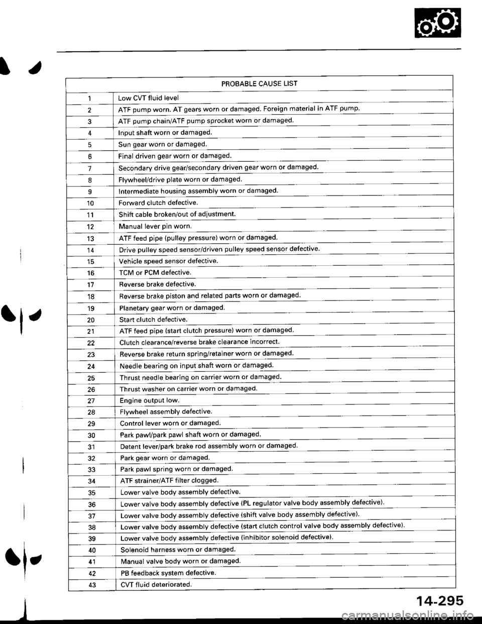
PROBABLE CAUSE LIST
Low CVT fluid level
ATF pump worn. AT gears worn or damaged. Foreign material in ATF pump.
ATF pump chain/ATF pump sprocket worn or damaged.
Input shaft worn or damaged.
Sun gear worn or damaged.
Final driven oear worn or damaqed,
Secondary drive gear/secondary driven gear worn or damaged-
5
6
1
8Flywheel/drive plate worn or damaged.
Intermediate housing assembly worn or damaged.9
'10Forward clutch defective.
Shift cable broken/out of adiustment.
M"nu"t t"uffi
ATF feed pipe (pulley pressure) worn or damaged.
Vchiclc speed sensor defective.
TCM or PCM defective.
Reverse brake detective.
1'�r
't2
13
14
16
'11
'18
1qPlanetary gear worn or damaged.
Sta rt clutch defective.
ATF feed pipe (start clutch pressure) worn or damaged
20
t't
Clutch clearance/reverse brake clearance incorrect.
23Reverse brake return spring/retainer worn or damaged
24Needle bearing on input shaft worn or damaged.
25Thrust needle bearing on carrier worn or damaged.
Thrust washer on carrier worn or damaged.
Enoine outout low.------------------------
Flvwhcel assemblv defective.
Control lever worn or damaged.
Park pawl/park pawl shaft worn or damaged
Detent lever/park brake rod assembly worn or damaged
27
29
30
32Park gear worn or damaged.
Park pawl spring worn or damaged.
ATF strainer/ATF filter clogged.
Lower valve body assembly defective.
Lower valve bodv assemblv defective (PL regulator valve body assembly defective)'
33
34
50
Lower valve bodv assembly defective (shift valve body assembly defective).
Lower valve bodv assemblv defective (start clutch control valve body assembly defective)'
39Lower valve bodv assemblv defective {inhibitor solenoid defective}
40Solenoid harness worn or damaged.
Manual valve body worn or damaged.
PB feedback system defective.
CVT fluid deteriorated.
41
43
14-295