1999 HONDA CIVIC crankshaft sensor
[x] Cancel search: crankshaft sensorPage 452 of 2189

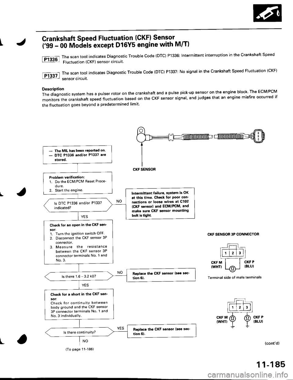
\Crankshaft Speed Fluctuation (GKFI Sensor .
firC- 48 Models, '99 - 00 D16Y5 engine with M/Tl
The scan tool indicates Diagnostic Trouble Code (DTC) P1336; Intermiftent interruption in the Crankshaft Speed
Fluctuation (CKF) sensor circuit.
ThescantooIindicatesDiagnosticTroub|ecode{DTC)P1337:NosignaIinthecrankshaftspeedF|uctuation(cKF}
sensor circuit.
D6scription
Thediagnosticsystemhasapu|serrotoronthecrankshaftandapu|sepick-upsensorontheengineblock.TheEcM/PcM
monitors the crankshaft speed ftuctuation based on the cKF sensor signal, and judges that 8n engine misfire occurred if
the fluctuation goes beyond a predetermined limit'
I
fPrk6l
lFr3g7-l
CKF SENSOR 3P CONNECTOR
L:l.)l l.' -Ir-T--T---.]l1 l2l3llL-''---r
CKFM I I CKFP
twrfit 1,.^ | lsLul\.7
Terminal side of male terminals
CKF MIWHT}
CKF PIBLUI
I(cont'd)
- The MtL hds been reported on.- DTC P1336 and/or P1337 a.e
stored.
P.oblem v€rific.tion:1. Do the ECM/PCM Reset Proce-
dure.2. Stan the enginelntormittont lailur6, tY3tom b OK
at thit tima. Chock tor Poor con'
nactions or loota wito! at C102
IC-KF son$rl .nd ECt /PCM, and
mrka suro CKF tonaor mounting
boh ittigM.
Chock for .n open in tho CKF aen-
30t:1. Turn the ignition switch OFF
2. Disconnect the CKF sensor 3P
connector,3. Measure the resista nce
between the CKF sensor 3P
connector terminals No. 1 and
No.3.
ls there 1.6- 3.2 kO?
Ch€ck tor a short in the CKF son'
30tiCheck {or continuitY between
body ground and the CKF sensor
3P connector termin6ls No. 1 and
No.3 individuallY.
(To page 11 184)
1 1-183
Page 453 of 2189

PGM-FI System
(From page 11 183)
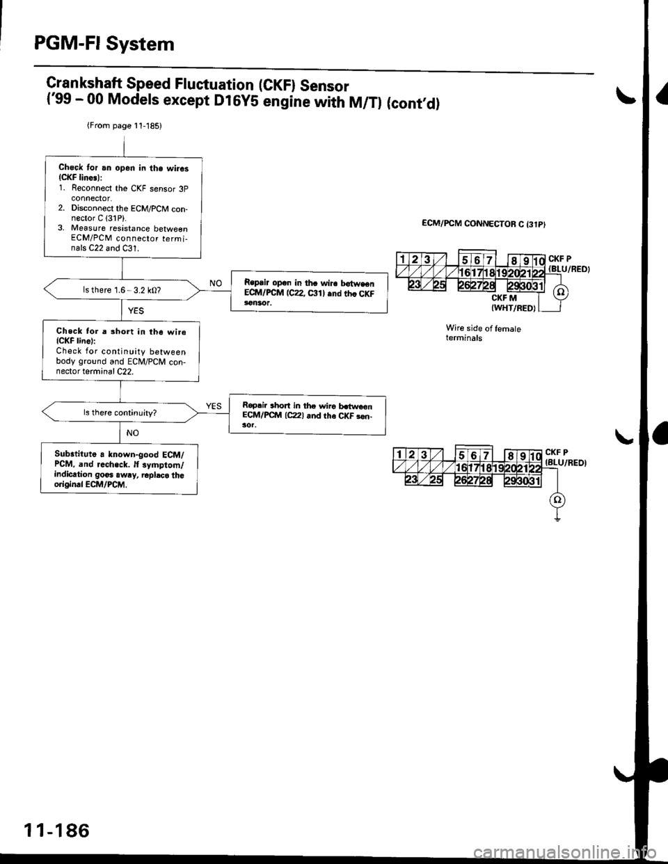
Check lor an open in the wiresICKF lines):1. Reconnect the CKF sensor 3p
2. Dlsconnect the ECM/PCM con-nector C (31P).3, Measure resistance betweenECM/PCM connector terminals Cl and Cl1.
Repair open in the wire betweenECM/PCM {C1, C11} and the CKFls there 1.6 3.2 kO?
Check for a short in the wire{CKF line}:Check for continuity betweenbody ground and ECM/PCM con,nector terminal C1.
Repair short in the wiro bstwoenECM/PCM {Cl) and the CKF son-
Substitute a known-good ECM/PCM, and recheck. lf symptom/indication goes awry, replace theoriginal ECM/PCM.
Crankshaft Speed Fluctuation (GKFI Sensor('96 - 98 Models,'99 - 00 D16V5 engine with M/Tl (cont,d)a\
ECM/PCM CONN€CTOR C (31P}
CKF P(8LU/REO)
CKF M(WHT/REO)Wire side of femaletermtnats
CKF P(BLU/RED)
6r l-i
rF
tl
a678910
12131115t61718
21272A2930
11-184
Page 454 of 2189

tCrankshaft Speed Fluctuation (CKF) Sensor -
('99 - 00 Mociels except D16Y5 engine with M/T)
The scan tool indicates Diagnostic Trouble code (DTC) P1336: Intermittent interruption in the crankshaft speed
Fluctuation (CKF) sensor circuit
The scan tool indicates Diagnostic Trouble Code (DTC) P1337: No signal in the Crankshaft Speed Fluctuation (CKF)
sensor circuat,
Description
Thediagnosticsystemhasapulserrotoronthecrankshaftandapu|sepick-upsensorontheengineb|ock.TheEcM/PcM
monitors the crankshaft speed fluctuation based on the cKF sensor signal. and judges that an engine misfire occurred if
the fluctuation goes beyond a predetermined limit'
I
Ftu6l
tF13g7l
CKF SENSOR 3P CONNECTOR
r--r t|-.r-r'--]llll l2l3ll.l---'.-T_
CKFM I I CKFP
twHTl |/Ai i lBlul--\9-
Terminal side oI male terminals
CKF M(WHT)CKF P(BLU)
t(cont'd)
1 1-185
- The MIL has b€on reportad on.- DTC P1336 and/or P1337 are
stored.
Problem verification:1. Do the ECM/PCM Reset Proce'
dure.2. Start the enginelntermittcnt failuro, sydcm is OK
ai this time. Check lot Poor con_
noctions or loo3e wiros at C102
ICKF s€nsor) and ECM/FCM, and
make suro CKF sansor mounting
bolt b tight.
Check tor an open in the CKF sen_
1. Turn the ignition switch OFF
2. Disconnect the CKF sensor 3P
3. Measure the resistance
between the CKF sensor 3P
connector terminals No. 1 and
No.3.
ls there 1.6 3.2 kO?
Check for a short in ihe CKF sen_
sot:Check for continuity betweenbody ground and the CKF sensor
3P connector terminals No 1 and
No.3 individuallY.
(To page 11-186)
Page 455 of 2189

PGM-FI System
Crankshaft Speed Fluctuation (GKFI Sensor('99 - 00 Models except D16YS engine with M/Tl (cont,d)I\
ECM/PCM CONNECTOR C 13lPI
Wire side of femaleterminals
aI
(Frorn page l1-185)
Check Ior an opsn in the wires(CKF lines):1. Reconnect the CKF sensor 3pconnector.2. Disconnect the ECM/PCM con-nector C {31P}.3. Measure resistance betw€enECM/PCM connector termi-nals C22 and C31.
Repair opqn in th. wire bo{weenECM/PCM (CZ, Ctll and th. CKFlon30r.
ls there 1.6-3.2 k0?
Check tor a short in the wireICKF line):Check for contin!ity betweenbody ground and ECM/PCM con-nector terminal C22.
Roplir thort in tho wirg b.iwoonECM/FC'ftl lc22l and tho CKF 3€n-
Substituto a known-good ECM/PCM, and r.ch.ck. It symptom/indication 90o. aw!y, 6pbco theoriginal ECM/PCM.
1 1-186
Page 456 of 2189

l,a
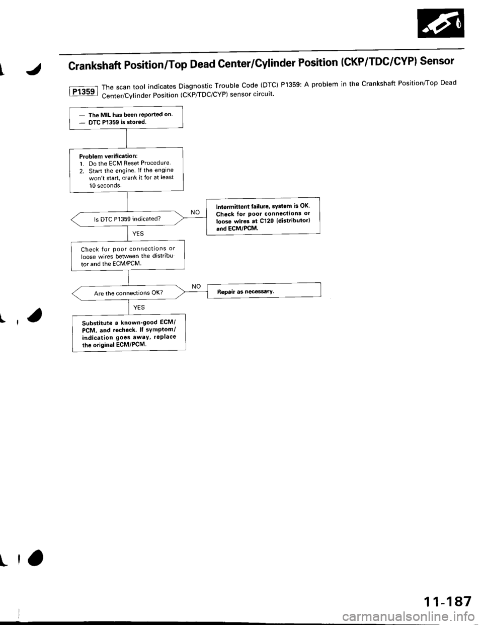
Crankshaft Position/Top Dead Center/Cylinder Position (CKP/TDC/CYPI Sensor
Thescantoo|indicatesDiagnosticTroub|ecode(DTc)P1359:Aprob|eminthecrankshaftPosjtion/TopDead
Center/Cvlinder Position (CKP/TDC/CYP) sensor circuit'
- The MIL has been reported on- DTC P1359 is stored
Problem veritication:1. Do the ECM Reset Procedure
2. Stan the engine lftheengine
won't start, crank it for at least
10 seconds-
lntermittent failure, sYstem is OK
Check for poor connecllon3 or
loose wires at C120 {distributor}and ECM,/PCM.
ls DTC P1359 indicated?
Check for poor connections or
loose wires between the distribu
tor and the ECM/PCM
Substitute a known'good ECM/
PCM, and rccheck. lt 3ymPtom/
indication goes awtY, rePlace
the original ECM/PCM.
r ta
11-1A7
Page 681 of 2189

Description
The automatic transmission is a 3-element torque converter and a dual-shaft electronically controlled unit which provides
4 soeeds forward and 1 reverse.
Torque Convertel, Geats, and Clutches
The torque converter consists of a pump, turbine and stator, assembled in a single unit. They are connected to the engine
crankshaft so they turn together as a unit as the engine turns. Around the outside of the torque converter is a ring gear
which meshes with the starter pinion when the engine is being started. The entire torque converter assembly seryes as a
flywheel while transmiuing power to the transmission mainshaft.
The transmission has two parallel shafts: the mainshaft and the countershaft. The mainshaft is in Iine with the engine
crankshaft. The mainshaft includes the 1st, 2nd and 4th clutches, gears tor 2nd, 4th, reverse and lst (3rd gear is integral
with the mainshaft, while the reverse gear is integral with the 4th gear). The countershaft includes the 3rd clutch, and
gears for 3rd,2nd, 4th, reverse. 1st and park. The gears on the mainshaft are in constant mesh with those on the counter-
shaft. When certain combinations of gears in transmission are engaged by clutches. power is transmitted from the main-
shaft to the countershaft to provide E, ld, E, and E positions.
Electronic Control
The electronic control svstem consists of the Powertrain Control Module {PCM), sensors, a linear solenoid and four
solenojd valves. Shifting and lock-up are electronically controlled for comtonable driving under all conditions. The PCM is
located below the dashboard, under the front lower panel on the passenger's side
Hydraulic Control
The valve bodies include the main vatve body, the secondary valve body, the regulator valve body, the servo body and the
lock-up valve body through the respective separator plates, They are bolted on the torque converter housang
The main valve body contains the manual valve, the 1-2 shift valve. the 2nd orifice control valve, the CPB {Clutch Pressure
Back-up) valve, the modulator valve. the servo control valve, the relief valve, and ATF pump gears The secondary valve
body contains the 2-3 shift valve. the 3-4 shift valve, the 3-4 orifice control valve, the 4th exhaust valve and the CPC (Clutch
pressure Control) valve. The regulator valve body contains the pressure regulator valve, the torque converter check valve,
the cooler relief valve, and the lock-up control valve. The servo body contains the servo valve which is integrated with the
reverse shift fork, and the accumulators. The lock-up valve body contains the lock-up shift valve and the lock-up timing
valve. The linear solenoid and the shift control solenoid valve Ay'B are bolted on the outside of the transmission housing,
and the lock-up control solenoid valve Ay'B is bolted on the outside of the torque converter housing. Fluid from regulator
passes through the manual valve to the various control valves. The clutches receive fluid from their respective teed pipes
or internal hydraulic circuit.
Shift Control Mechanism
Input from various sensors located throughout the car determines which shift control solenoid valve the PCM will activate
Activating a shift control solenoid valve changes modulator pressure, causing a shift valve to move. This pressurizes a line
to one of the clutches, engaging that clutch and its corresponding gear, The shift control solenoid valves A and B are con-
trolled by the PCM.
Lock-up Mechanism
In ,Dt1 position, in 3rd and 4th. and in E position in 3rd, pressurized fluid is drained from the back of the torque converter
through a fluid passage, causing the lock-up piston to be held against the torque converter cover. As this takes place, the
mainshaft rotates at the same as the engine crankshaft. Together with hydraulic control, the PCM optimizes the timing of
the lock-up mechanism. The lock-up valves control the range of lock-up according to lock-up control solenoid valves A and
B, and linear solenoid. When lock-up control solenoid valves A and B activate, the modulator pressure changes The lock-
up control solenoid valves A and B and the linear solenoid are controlled by the PCM.
(cont'd)
14-3
Page 873 of 2189

Description
The Continuously Variable Transmission (CVT) is an electronically controlled automatic transmission with drive and driv
en Oullevs, and a steel belt. The CVT provides non stage speeds forward and one reverse. The entire unit is positioned in
line with the engine.
Transmission
Around the outside of the flywheel is a ring gear which meshes with the starter pinion when the engine is being staned.
The transmission has four parallel shafts: the input shaft, the drive pulley shaft. the driven pulley shaft, and the secondary
gear shaft. The input shaft is in line with the engine crankshaft. The drive pulley shaft and the driven pulley shaft consist of
movable and fixed face pulleys. Both pulleys are linked by the steel belt.
The input shaft includes the sun gear. The drive pulley shaft includes the forward clutch which mounts the carrier assem-
bly on the forward clutch drum. The carrier assembly includes the pinion gears which mesh with the sun gear and the ring
gear. The ring gear has a hub-mounted reverse brake disc.
The driven pulley shaft includes the start clutch and the secondary drive gear which is integral with the park gear' The sec-
ondary gear shaft is positioned between the secondary drive gear and the final driven gear. The secondary gear shaft
includes the secondary driven gear which serves to change the rotation direction. because the drive pulley shaft and the
driven oullev shaft rotate the same direction. When certain combinations of planetary gears in the transmission are
engaged by the clutches and the reverse brake, power is transmitted from the drive pulley shaft to the driven pulley shaft
to provide E, E, E, and El.
Electronic Control'96 - 98 Models:
The electronic control system consists of the Transmission Control Module (TCM), sensors, three linear solenoids, and a
inhibitor solenoid. Shifting is electronically controlled under all conditions'
The TCM is located below the dashboard, behind the kick panel on the driver's side.'99 - 00 Models:
The electronic control svstem consists of a Powertrain Control Module (PCM), sensors, three linear solenoids and an
inhibitor solenoid. Shifting is electronically controlled under all conditions. A Grade Logic Control System to control shift-
ing in E position while the vehicle is ascending or descending a slope.
The PCM is located below the dashboard, under the kick panel on the passenger's side.
Hydraulic Control
The lower valve body assembly includes the main valve body, the Pressure Low (PL) reguiator valve body, the shift valve
body, the start clutch control valve body, and the secondary valve body. They are positioned on the lower part of the
transmission housing.
The main valve body contains the Pressure High (PH) control valve, the lubrication valve, and the pitot regulator valve.
The secondary valve body contains the PH regulator valve, the clutch reducing valve, the start clutch valve accumulator,
and the shift inhibitor valve. The PL regulator valve body contains the PL regulator valve and the PH-PL control valve
which is ioined to the PH,PL control linear solenoid. The inhibitor solenoid valve is bolted on the PL regulator valve body.
The shift valve body contains the shift valve and the shift control valve. which is joined to the shift control linear solenoid.
The start clutch control valve body contains the start clutch control valve, which is joined to the start clutch control linear
solenoid. The linear solenoids and the inhibitor solenoid are controlled by the TCM or PCM. The manual valve body which
contains the manual valve and the reverse inhibitor valve, is bolted on the intermediate housing.
The ATF pump assembly is located on the transmission housing, and is linked with the input shaft by the sprockets and
the sprocket chain. The pulleys and the clutch receive fluid from their respective feed pipes, and the reverse brake receives
fluid from internal hydraulic circuit.
Shift Control Mechanism
Input from various sensors located throughout the vehicle determines which linear solenoid the TCM or PCM will activate.
Activating the shift control linear solenoid changes the shift control valve pressure, causing the shift valve to move. This
pressurizes the drive pulley pressure to the drive pulley and the driven pulley pressure to the driven pulley and changes
their effective pulley ratio. Activating the start clutch control linear solenoid moves the start clutch control valve. The start
clutch control valve uncovers the port, providing pressure to the start clutch to engage it(cont'd)
14-195
,!
Page 1025 of 2189

l.
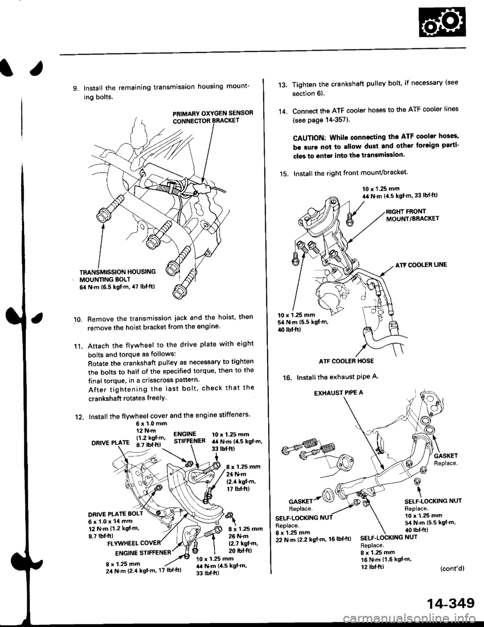
9. Install the remaining transmission housing mount-
ing bolts.
PRIMARY OXYGEN SENSOR
Remove the transmission jack and the hoist. then
remove the hoist bracket from the engine'
Attach the flvwheel to the drive plate with eight
bolts and torque as follows:
Rotate the crankshaft pulley as necessary to tighten
rhe bolts to half of the specified torque, then to the
final torque, in a crisscross pattern.
After tightening the last bolt. check that the
crankshaft rotates freelY.
10.
11.
12. Install the flywheel cover and the engine stiffeners
DRIVE
6xl.0mm12 N.m
- l12 kgf'm'rE 8.7 tbf.ftl
ENGINESTIFfENEB10 x 1.25 mmart N.m la.s kgt.m,33 tbtftt
8 x 1.25 mm24 N.m(2.1 kgf'm,17 tbt.ftt
DRIVE PI.ATE BOLT
6x1.0x14mm12 N.m {1.2 kgt m.
8.7 lbf,ftl8 x 1.25 mm26 N.m
12.7 kqfin,20 rbt'ftlFLYUTHEEL
ENGINE STIFFENER
8 x 1.25 mm10 x 1.25 mmr,a N.m {4,5 kgf m,
33 tbf.ftl
TRANSMISSION HOUSING
MOUNNNG BOLT
6il N.m {6.5 kgf.m, 47 lbf'ftl
24 N.m (2.4 kgt'm, '17 lbf'ftl
22 N.m t2.2 kgl m, 16lbf'ftl
14-349
13.
14.
Tighten the crankshaft pulley bolt, if necessary (see
section 6).
Connect the ATF cooler hoses to the ATF cooler lines
(see page 14-357).
CAUTION: Whilo connecting the ATF cooltr hGes,
b€ sure not lo allow dust and other loreign parti-
cles to entg. into the transmission.
15. Installthe right front mounvbracket'
10 x 1.25 mm
a,r N.m {4.5 kgf'm,33 lbt ftl
RIGHT FRONTMOUNT/BRACKET
ATF COOLER LINE
10 x 1 .25 mm54 N.m {5.5 kgt'm,
4{) tbl.ftt
ATF COOI,TR HOSE
16. Installthe exhaust PiPe A.
EXHAUST PIPE A
GASKETReplace.
@
\SELF.LOCKING NUTReplace.10 x 1.25 mm5/a N.m {5.5 kgt m,irc lbf.ft)
(cont'dl
*s$o
oor*rr-@Replace.
SELF.LOCKINGReplace.8 x 1.25 mmSELF.LOCKING NUT
Replace.8 x 1.25 mm16 N.m {1.6 kgl'm,12 tbl.ftt