Page 1146 of 2189

Rear Suspension
Suspension Arms Replacement ('gg 2D Si and Si-R models)
CAUTION:
. Roplace the self-locking nut after removal.' The vehicle should be on the gtound before any bohs or nuls connected to rubber mounts or bushing are tightened.
NOTE:
' Make sure the toe adjusting borts on the compensator arm are insta|ed in the same direction.. "t UP L" or "t UP LH G" or "t Up LK" or "l Up LS,, is stamped on the left upper arm and ,,t Up R,, or "t Up RH G,,"i UP RK" or "t UP RS" on the right upper arm.. The right and left compensator arm are symmeticar. Install sothe"upr"markpointstothefront.. After installing the suspension arm, check the wheel atignment and adiust if necessary,
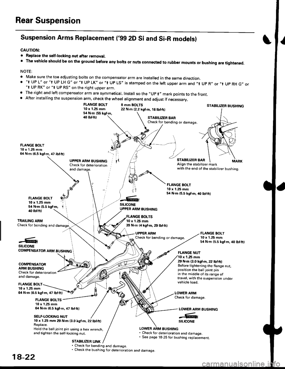
FLANGE BOLT'10 x 1.25 mm54Nm155kgl.m,,rc lbf.ftl
8 rhm BOLTS22 N.m {2.2 kgf.m, 16 tbtfrlSTABILIZER BUSHTNG
FLANGE BOLT10 x 1.25 rnm54 N.m {5.5 kgt m, iro lbf.ft)
STAEILIZER BARCheck for bending or damage.
FLANGE BOLT10 x 1 .25 mm64 N m {5.5 kgf.m,47 lbtftl
FLANGE BOLT10 x 1.25 mm54 N.m 15.5 *gf.m,
and
UPPER ARM BUSHINGCheck for deteriorationAlign the stabitizer markwith the end ot the stabilizer bushing.
FLANGE BOLT'10 x 1.25 mm54 N.m 15.5 kgt.m, a0 lbtftl
stLrcoNEUPPER ARM BUSHINGiO lbf.ftl
TRAILING ARMCheck for bending and
EOLTS10 x 1.25 mm39 N m ll kgf.m, 29 lbf.ft)
UPPER ARMCheck for b€nding or damage.#@lstLtcoNECOMPENSATOR ARM BUSHING
COMPENSATORARM BUSHINGCheck for deteriorationand damage.
FLANGE NUTr '1.25 mm29 N.m {3.0 ksl.m,22 lbtft}Belore tightening the flange nut,position the ball joint pinin the middle ol its range oftravel, with the suspension undervehicle load.
LOWER ARMCheck for damage-
BUSHING
FLANGE BOLTl0 x 1.25 mm6l N.m 16.5 kg{.m, a7 lbt.ftl
FLANGE BOLTS10 x 1,25 mm64 N.m {6.5 kgf.m, 47 lbf.ftl
SELF.LOCKNG NUT
LOWER ARM
-GrstltcoNE10 x 1.25 mm 29 N.m (3.0 ksl.m, 22 tbtfrlReplace.Hold the ball ioinl pin using a hex w.enct.and tighten the selfjocking nut.
STABILIZEB LINK
LOWER ARM BUSHING. Check for deterioration and damaoe.' See page 18 25 for bushing replaciement.
' Check for bending and damage.. Check the bushing for deterioration ano oamage.
18-22
Page 1394 of 2189

Troubleshooting -'99 - 00 Models
Self-diagnosis Function
The heater control panel has a self-diagnosis function.
Running the Self-diagnosis Funqtion
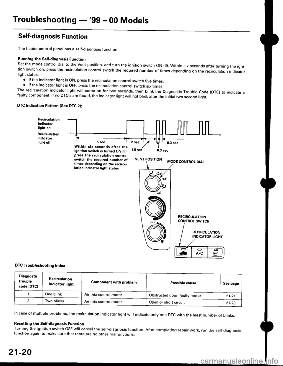
Set the mode control dial to the Vent position, and turn the ignition switch ON fll). Within six seconds after turnang the igni_tion switch on. press the recirculation control switch the required number of times depending on the recirculation indicatorlight status:
.lftheindicatorlightisON,presstherecirculationcontrolswitchfivetrmes.
.lftheindicatorlightisOFF,presstherecirculationcontrol switch six rrmes.The recirculation indicator light will come on for two seconds. then blink the Diagnostic Trouble code {DTc} to indicate afaulty component. lf no DTc's are found, the indicator light will not blink after the initial two second liqht.
DTC Indication Pattern (S6e DTC 2l:
Recirculationindicato.light on
Recirculationindicatorlight off2 sec
,/1.5 soct
' 0,3 secWithin six seconds atter theignition switch is turned ON (lll,pross the recirculation controlswitch the required number ottimes depending on the rocircu-lation indicetor light status
0.3 sec
VENT POSITIONMODE CONTROL DIAL
RECIRCULATIONCONTROL SWTCH
DTC Troubleshooting Index
Diagnostic
trouble
code (DTCI
Rgcirculation
indicator lightComponent with problemPossible causeSee page
One blinkAir mix control motorObstructed door, laulty motor21-21
2Two blinksAir mix control motorOpen or short circuit21-23
ln case of multiple problems, the recirculation indicator light will indicate only one DTc with the least number of blinks.
Resetting the Self-diagnosis FunctionTurning the ignition switch OFF will cancel the self-diagnosis function, After completing repair work, run the setf diagnosisfunction again to make sure that there are no other malfunctions.
21-20
@
At
V'
Page 1718 of 2189

Cruise Control
t
D=
t
Astuator Replacement
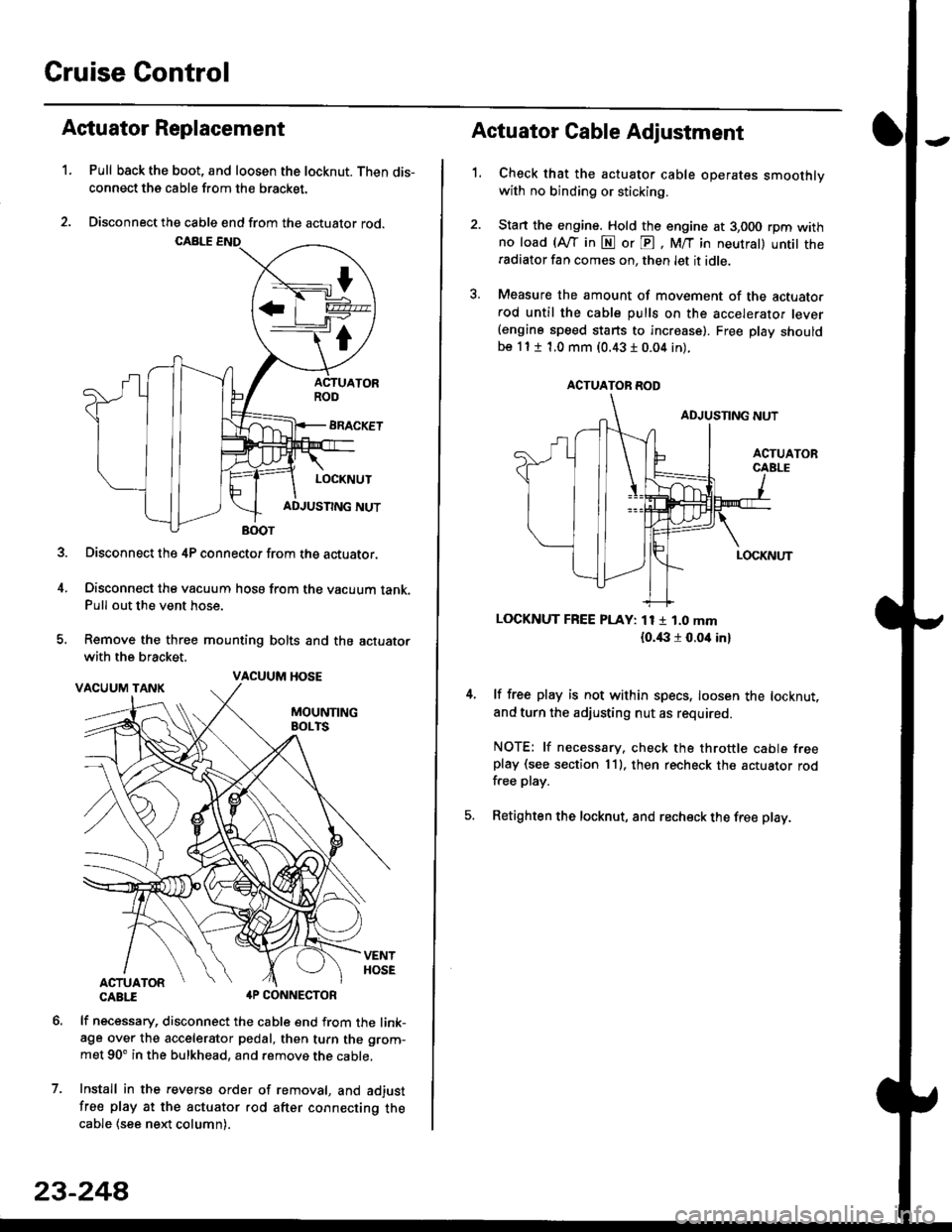
1.Pull back the boot, and loosen the locknut. Then dis-
connect the cable from the bracket.
Disconnect the cable end from the actuator rod.
Disconnect the 4P connector from the actuator.
Disconnect the vacuum hosa from the vacuum tank.Pull out the vent hose.
Remove the three mounting bolts and the actuator
with the bracket.
CABTI aP CONNECTOR
lf necessary, disconnect the cable end from the link-age over the accelerator pedal, then turn the grom-
met 90' in the bulkhead, and remove the cable,
Install in the revers€ order of removal, and adjust
free play at the actuator rod after connecting thecable (see ne)d column).
7.
VACUUM HOSE
23-244
1.
Actuator Cable Adjustment
Check that the actuator cable operates smoothlywith no binding or sticking.
Stan the engine. Hold the engine at 3,000 rpm withno load (Afl'in N or E, M/T in neutral) untit theradiator fan comes on, then let it idle.
Measure the amount of movement of the actuato.rod until the cable pulls on the accelerator lever(engine speed starts to increase). Free Dlay shouldbe 11 t 1.0 mm (0.43 I 0.04 in).
LOCKNUT FREE PLAY: 11 1 1.0 mm
{o.i|:l r 0.oit in}
lf free play is not within specs, loosen the locknut,
and turn the adjusting nut as required.
NOTE: lf necessary. check the throttle cable freeplay (see section 11). then recheck the actuator rodfree play.
Retighten the locknut, and recheck the free play.
ACTUATOR ROD
Page 1743 of 2189

Description
)
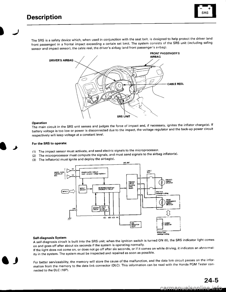
The sRS is a safety device which, when used in coniunction with the seat belt, is designed to help protect the driver land
front passenger) in a frontal impact exceeding a certain set limit. The system consists of the sRS unit {including safing
sensor and impact sensor), the cable reel, the driver's airbag (and front passenger's airbag)
FRONT PASSENGEB'SAIRAAG
DRIVER'S AIRBAG
CABLE REEL
SRS UNtT
t
Operation
The main circuit in the SRS unit senses and judges the force of impact and, if necessary, ignites the inflator charge(s) lf
battery voltage is too low or power is disconnected due to the impact, the voltage regulator and the back-up power clrcult
resoectivelv will keep voltage at a constant level.
For the SRS to operate:
(1) The impact sensor must activate. and send electric signals to the mlcroprocessor'
(2) The microprocessor must compute the signals' and must send signals to the airbag inflator(s)'
{3) The inflator(s) must ignite and deploy the airbag(s)'
_"-_-l
Ir3B!#h i
!.. I
ffi,*
Self-diagnosis System
A self-diagnosis circuit is built into the SRS unit; when the ignition switch is turned ON (ll), the SRS indicator light comes
on and goes off after about six seconds if the system is operating normally
lf the liglt does not come on, or does not go off after six seconds, or if it comes on while driving, it indicates an abnormal-
ity in the system. The system must be inspected and repaired as soon as possible
For better serviceability, the memory will store the cause of the malfunctlon, and the data link circuit passes on the infor-
mation from the memory to the data link connector (DLC). This intormation can be read with the Honda PGM Tesler con-
nected to the DLC (16P).
l,
24-5