Page 1708 of 2189
Moonroof
1.
Switch Test
Carefully remove the switch from the driver's dash-
board lower cover {see page 23-205}.
Check for continuitv between the terminals in each
switch position according to the table.
Terminal
t*',*-----__\I234
ut-t-
OPENo--o
CLOSEo---o
TILTo--o
23-234
Motor Test
'1.Remove the headliner (see section 20).
Disconnect the 2P connector from the moonroof
motor.
Terminal side of male terminals
Check the motor by connecting power and ground
according to the table.
4. lf the motor does not run, replace it (see section 20).
NOTE: See Closing Force Check in section 20 for
motor clutch test.
\_____lTr1
Position
,l
OPENo@
CLOSE@
Page 1712 of 2189
Cruise Control
Gontrol Unit Input Test
SRS components are located in this area. Review the SRS component locations, precautions, and procedures in the SRSsection (24) before performing repairs or service.
1. Remove the driver's dashboard lower cover and knee bolster (see section 20).
2. Disconnect the l4P connector from the control unit.
3. Inspect the connector and socket terminals to be sure they are all making good contact.
lf the terminals are bent, loose, or corroded, repair them as necessary, and recheck the system.lf the terminals look OK, make the following inpul tests at the connecror.- lf any test indicates a problem, find and correct the cause, then recheck the system,- lf all the input tests prove OK, the control unit must be faulty; replace it.
14P CONNECTOR
CRUISE CONTROL UNIT
*i '99 00 models with A/T
23-242
GRN/WHT LT GRN/RED LT GRN/BI-K
8LU/GRN*
Wire side of female terminals
Page 1714 of 2189
Cruise Gontrol
3.
1.
2.
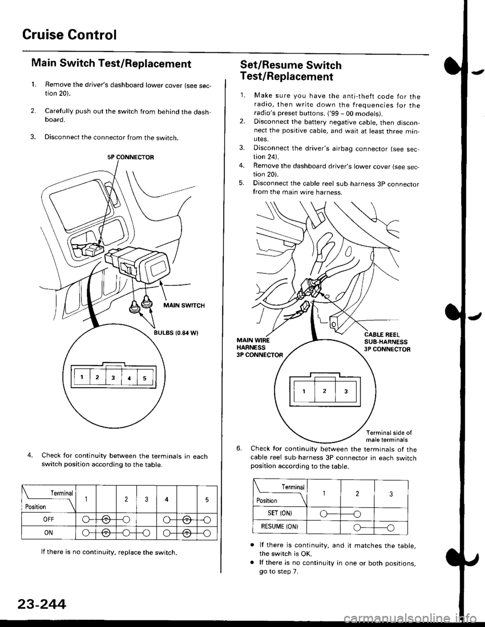
Main Switch Test/Replacement
Remove the driver's dashboard lower cover (see sec-tion 20).
Carefully push out the switch from behind the dashboard.
Disconnect the connector from the swtrcn.
MAIN SWITCH
BULBS {0.84 Wt
Check for continuity between the terminals in eachswitch position according to the table.
lf there is no continuity. reDlace the switch.
4.
Terminal
r**
--\235
OFFo--oGa\-o\:./\a/
ONo-/a-oo--o\:/\:/
23-244
Set/Resume Switch
5.
Test/Replacement
2.
1.
MAIN WIREHARNESS3P CONNECTOR
Make sure you have the anti-theft code for theradio, then write down the frequencies for theradio's preset buttons. ('99 - 00 models).Disconnect the battery negative cable, then discon-nect the positive cable, and wait at least three min-utes.
Disconnect the driver's airbag connector (see sec-tion 24).
Remove the dashboard driver's lower cover (see sec,tion 20).
Disconnect the cable reel sub harness 3p connectorfrom the main wire harness.
CABLE BEELSUB-HARNESS3P CONNECTOS
Terminalside ofmale terminals
Check for continuity between the terminals of thecable reel sub-harness 3P connector in each switchposition according to the table.
L Terminal
Position123
SET (ON}o----o
BESUi,|E IONIo-----o
lf there is continuity, and it matches the table,the switch is OK.
lf there is no continuity in one or both positions,
go to step 7.
Page 1715 of 2189
7. Remove th€ two screws, then remove the switch'
Check for continuity between the terminals in switch
position according to the table.
Terminal
t"-"t*
-\23
SET (ON)o--o
RESUI\4E {ON}o----o
lf there is continuity, and it matches the table,
replace the cable reel.
lf there is no continuity in one or both positions,
reDlace the switch.
8.
SET/NESUME
l-l
23-245
11.
q
10.
12.
lf all tests prove OK, reconnect the cable reel and
cable reel sub-harness connector, then reinstall the
steering column covers
Reconnect the driver's airbag connector. and rein-
stall the access panel on the steering wheel.
Reconnect the battery positive cable, then the nega-
tive cable.
After connecting the airbag connectors, confirm
proper system operation; Turn the ignition switch ON
(ll); the SRS indicator light should come on for about
six seconds and then go off.
Enter the anti-theft code for the radio, then enter the
customer's radio station presels {'99 -00 models)'
Page 1747 of 2189
)
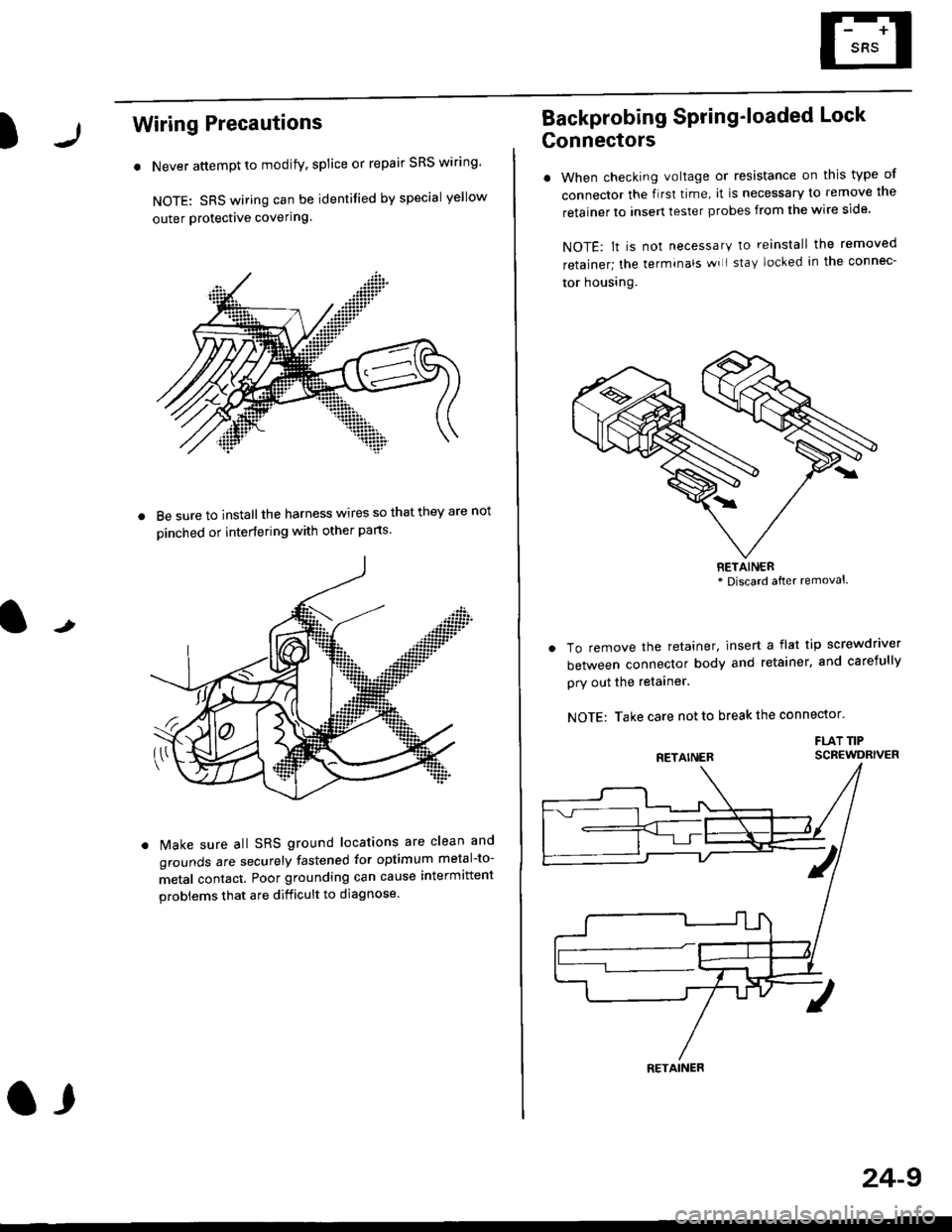
Wiring Precautions
. Never attempt to modify, splice or repair SRS wiring'
NOTE: SRS wiring can be identified by special yellow
outer Protective covering.
8e sure to install the harness wires so that they are not
oinched or interfering with other parts.
t
Make sure all SRS ground locations are clean and
grounds are securely fastened for optimum metal-to-
metal contact. Poor grounding can cause intermittent
problems that are difficult to diagnose.
a,
24-9
Backprobing Spring'loaded Lock
Gonnectors
. When checking voltage or resistance on this type of
connector the flrst time, it is necessary to remove lne
retainer to insert tester probes from the wire side.
NOTE: lt is not necessary to reinstall the removed
retainer; the terminals wi I stay locked in the connec-
tor housrng.
To remove the retainer, insert a flat tip screwdriver
between connector body and retainer, and carefully
pry out the retainer.
NOTE: Take care not to break the connector.
FLAT TIPSCBEWDRIVER
RETAINER* Discard after removal.
RETAINER
Page 1780 of 2189
Troubleshooting
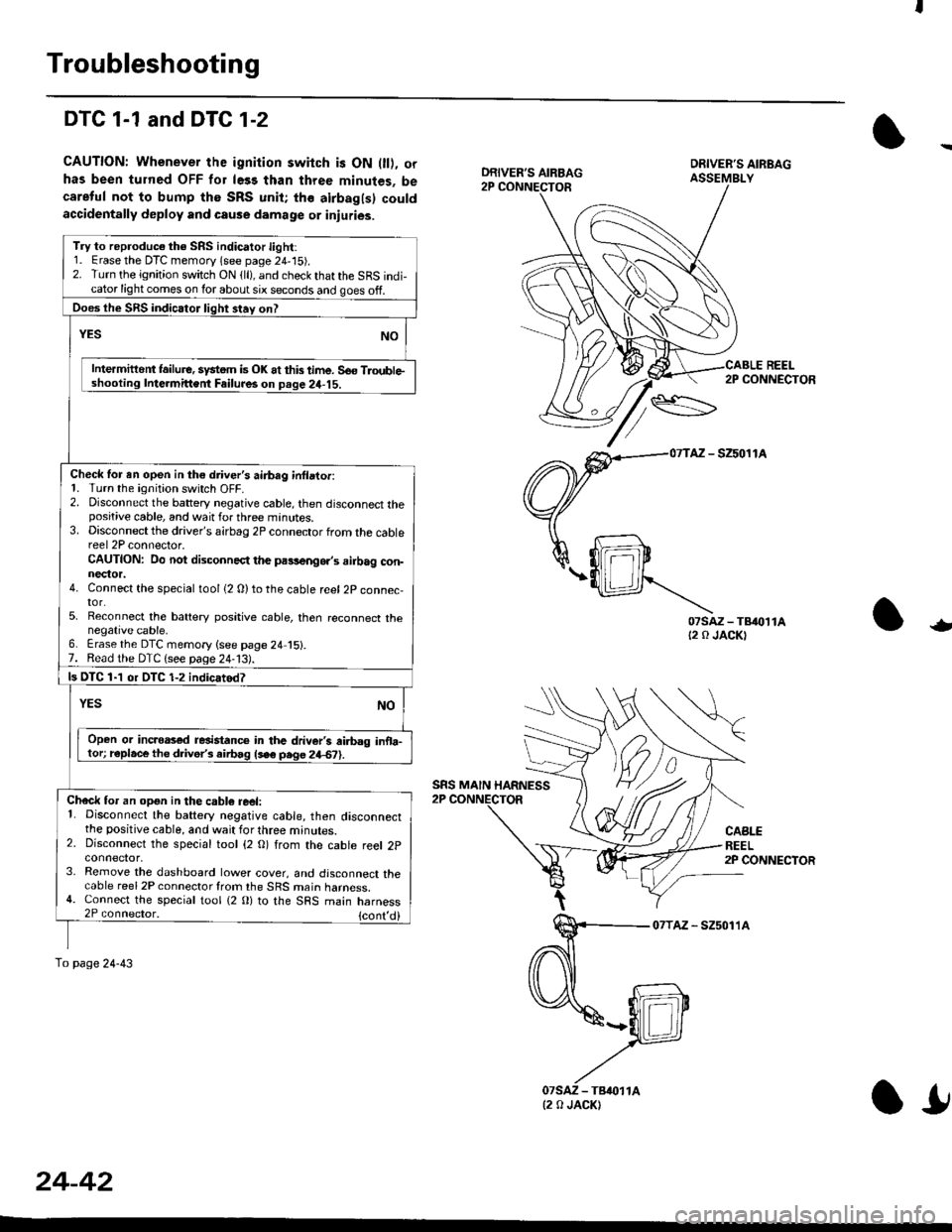
DTC 1-1 and DTG 1-2
CAUTION: Whenever the ignition switch is ON 0l), orhas been turned OFF for le33 than three minutes, becareful not to bump the SRS unit; the airbagls) couldaccidentally deploy and cause damage or inluries.
REEL2P CONNECTOR
AZ - SZ5011A
07sAz-TB{0t1At2 0 JACKT-
CABLEREEL2P CONNECTOR
07TAz - SZ5011A
DRIVER'S AIRBAG
SRS MAIN HARNESS
Try to reproduc€ the SRS indicator light:1. Erase the DTC memory lsee page 24,'15).2. Turn the ignition switch ON {ll), and check that the SRS indi-cator light comes on lor about six seconds and goes off.
Does the SRS indicator liqht 3tav on?
Intermittent lailure. system is OK at this time. So€ TloubleIntermittent Failur6 on Deqe 24-15.
Check for en open in th€ driver's airbag inllator:1. Turn the ignition switch OFF.2. Disconnect the battery negative cable, then disconnect thepositive cable, and wait for three minutes.3. Disconnect the driver's airbag 2P connector from the cablereel 2P connector.CAUTION: Do not disconnect the pa9,!eng6.,s ailbag con-nector.4. Connect the special tool {2 0)to the cable reel 2P connec,tor.5. Reconnect the battery positive cable, then reconnect thenegative cable,6. Erase the DTC memory {see page 24 15}.7. Read the DTC {see paqe 24-13).
ls OTC 1-1 or DTC 1-2 indicatod?
Open or incroas€d resistanc€ in the driver's ai.bag inoa-tor; r€place the d ve/s airbag lse6 pege 24€?).
Check for an opgn in the cabl6 reel:1. Disconnect the battery negative cable, then disconnectthe positive cable, and wait for three minutes.2. Disconnect the special tool {2 O) from the cable reel 2pconnector,3. Remove the dashboard lower cover, and disconnect thecable reel 2P connector from the SRS main harness.4. Connect the special tool {2 0} to the SRS main harness2P connector, {cont,
To page 24-43
(2 0 JACK)
24-42
l!
Page 1782 of 2189
Troubleshooting
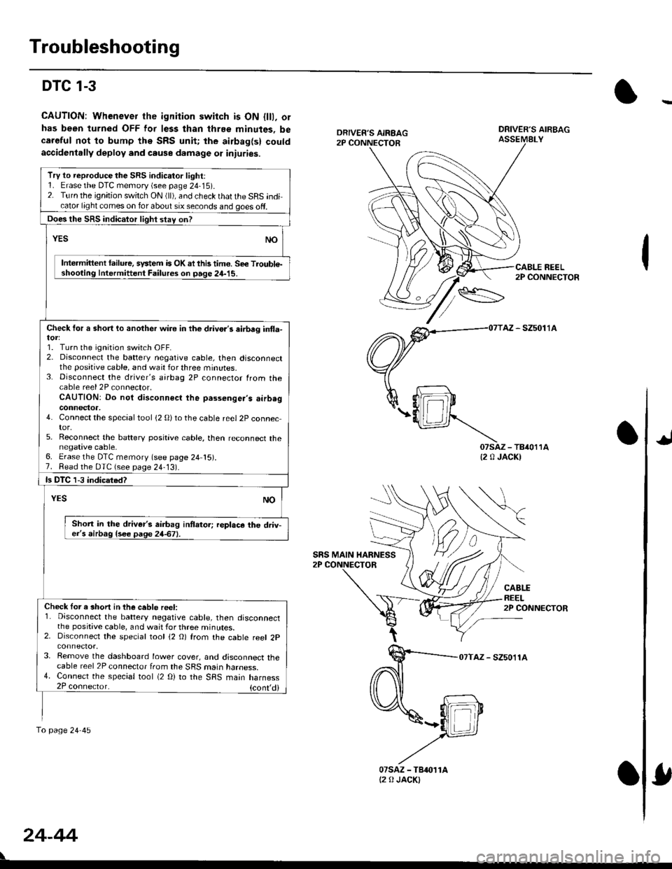
DTC 1-3
CAUTION: Whenever the ignition switch is ON {lll, orhas been turned OFF lor less than thrEe minutes, becaroful not to bump the SRS unit; the airbag(s) couldaccidenlally deploy and cause damage 01 iniuries.
DRIVER'S AIRBAGASSEMALY
REEL2P CONNECTOR
AZ - SZ5011A
07saz - TB4011A{2 0 JACK)
CABLEREEL2P CONNECTOR
07TAZ - SZ5011A
TrV to reproduce the SRS indicator light:1. Erase the DTC memory (see page 24-15).2. Turn the ignition switch ON (ll), and check that the SRS indicator light comes on for about six seconds and goes off.
Does the SRS indicalor light stav on?
YESNO
Intermittent lailure. system is OK ai this tim€. Se€ Troubl€-shooting Intermittent Failures on page 24-15.
Check tor a short lo another wire in the drivo.'s eirbrg in{la-
1. Turn the ignition switch OFF.2. Disconnect the battery negative cable, then disconnectthe positive cable, and wait for three minutes.3. Disconnect the driver's airbag 2P connector from thecable reel 2P connector,CAUTION: Do not disconnect the passenger's airb.gconnector,4. Connect the special tool (2 0)to the cable reel 2P connector,5. Reconnect the baftery positive cable, then reconnect thenegative cable,6. Erase the DTC memory (see page 24 15).7. Read the DTC (see page 24-13).
ls DTC 1-3 indicated?
NOYES
Shon in the driver's airbag intlator; replace the driv-er's airbag {see page 24-67}.
Check lor a short in the ceble reel:1. Disconnect the battery negative cable, then disconnectthe positive cable, and wait for three minutes.2. Disconnect the special tool (2 O) from the cable reel 2p
3. Remove the dashboard lower cover, and disconnect thecable reel 2P connector from the SRS marn naroess.4. Connect the special tool (2 O) to the SRS main harness2P coonector. {cont,di
fo page24-45
SRS MAIN HARNESS
24-44
07sAz - TBr011At2 0 JACKI
Page 1784 of 2189
Troubleshooting
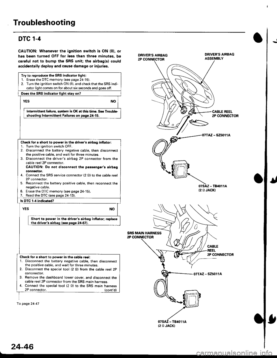
!DTC 1-4
CAUTION: Whenever ths ignition 3wiich is ON {lll, or
has boen turned OFF tor loss than three minutes, bs
caroful not to bump the SRS unit; the airbagls) could
accidoDtally deploy and cause damage or iniulies.
07SAZ - TB,()11A(2 0 JACKI
CABLEREEL2P CONNECTOR
07TAZ - Szsol'�lA
24-46
DRIVER'S AIRBAG
CABLE REEL2P CONNECTOR
Try to roproduc. the SRS indic.lor lightr1. Erase the DTC memory (see page 24-15).2. Turn the ignition switch ON (ll), and check that the SRS indi-cator light comes on tor about six seconds and goes off.
Ooes th6 SRS indicltor liqht stey on?
YESNO
Intermitid{ failure, 3y3tem b OK at this time. S€e Troublo-shooting Intormittont Failurss on pago 24.15.
Check for a 3hort to powo. in the d.iver's .irbag inflator:1. Turn the ignition switch OFF.2. Disconnect the baftery negative cable, then disconnectthe positive cable, and wait for three minut6s.3. Disconnect the driver's airbag 2P connector from thecable reel 2P connector.CAUTION: Do not disconnoct the parsengcr'r airbagconnactoa.4. Connect the SRS service connector (2 O) to the cable reel2P connector.5. Reconnect the battery positive cable, then reconnect thenegative cable.6. Erasethe DTC memory (see page 24-15).7. Read th6 DTC {seo page 24-13},
ls OTC 1-4 indic.tedT
YESNO
Short to pow.r in the driver'i rirbrg inilrtor; r€pl.cothe driver'! airbag l!e. paga 24-67).
Check for a ahort to Dow€r in tha crblo.eet:1. Disconnect the battery negative cabl€, then disconnectthe positive cable, and wait for three mrnur€s.2. Disconnect the special tool (2 O) trom the cable reel 2Pcononector.3. Bemove the dashboard lower cover, and disconnect thecable reel 2P connector trom th€ SRS main harness.4. Connect the special tool 12 0) to the SRS main harness2P connector. (cont'd)
fo page 24-47
SRS MAIN HABNESS
t2 0 JACK)