Page 1270 of 2189
Rear WindowOuarter Glass
Installation {cont'd)
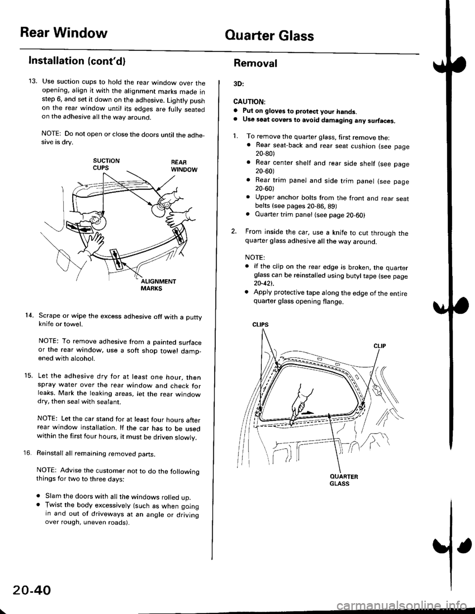
13. Use suction cups to hold the rear window over theopening. align it with the alignment marks made inslep 6. and set it down on the adhesive. Lightly pushon the rea. window until its edges are fully seatedon the adhesive allthe way around.
NOTE: Do not open or close the doors until the adhe_sive is drv.
sucTtoNCUPS
Scrape or wipe the excess adhesive off with a puttyknife or towel.
NOTE: To remove adhesive from a painted surfaceor the rear window. use a soft shop towel damp-ened with alcohol.
Let the adhesive dry for at least one hour. thenspray water over the rear window and check forleaks, Mark the leaking areas, let the rear windowdry, then seal with sealant.
NOTE: Let the car stand for at least four hours afterrear window installation. lf the car has to be usedwithin the first four hours, it must be driven slowly.
Reinstall all remaining removed parts.
NOTE: Advise the customer not to do the followingthings for two to three days:
. Slam the doors with all the windows rolled up.. Tr,vist the body excessively lsuch as when goingin and out of driveways at an angle or drivingover rough, uneven roads).
14.
15.
\
20-40
Removal
3D:
CAUTION:
a Pul on gloves to protect your hands.. Use seat covers to avoid damaging any surfaces,
1. To remove the quarter glass, first remove the:. Rear seat-back and rear seat cushion (see page20_80)
. Rear center shelf and rear side shelf lsee page20_60)
. Rear trim panel and side trim panel (see page20_60)
. Upper anchor bolts from the front and rear seatbelts {see pages 20-86. 89). Ouarter trim panel (see page20-60)
2, From inside the car, use a knife to cut through thequarter glass adhesive all the way around.
NOTE:
. lf the clip on the rear edge is broken, the quarterglass can be reinstalled using butyltape (see page20-421.
. Apply protective tape along the edge of the entirequarter glass opening flange.
OUARTERGLASS
Page 1272 of 2189
Quarter Glass
Installation (cont'd)
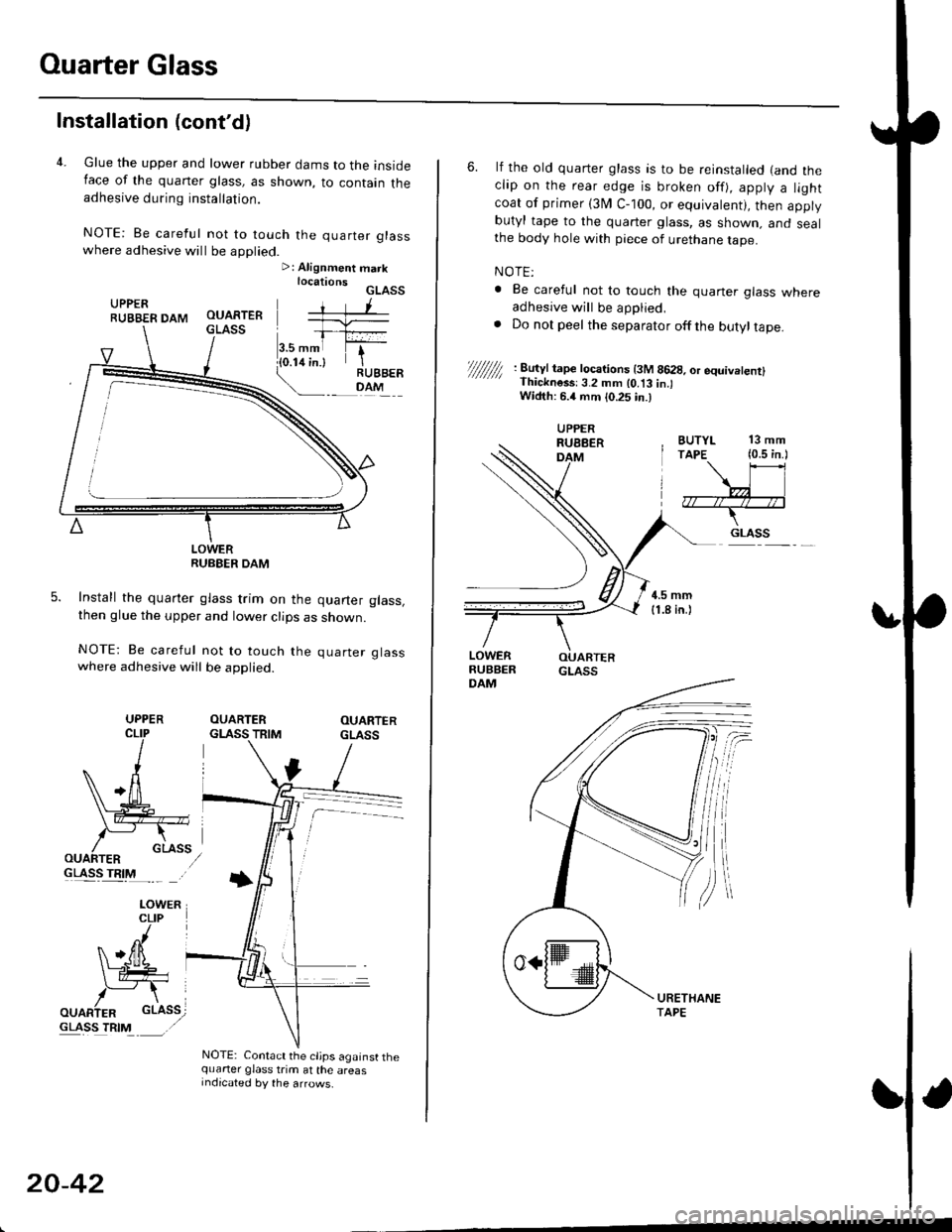
4. Glue the upper and lower rubber dams to the insideIace of the quaner glass, as shown, to contain theadhesive during installation.
NOTE: Be careful not to touch the quarter glasswhere adhesive will be applied.>: Alignment marklocationsGLASSUPPERRUBBER DAM
LOWERRUBEER DAM
Install the quarter glass trim on the quarter glass,then glue the upper and lower clips as shown.
NOTE: Be careful not to touch the quarter glasswhere adhesive will be applied.
OUARTERGLASS TRIMOUARTERGLASS
GLASS TRIM
NOTE: Contact the cljps against thequarter glass trim at the areasIndicated by the arrows.
UPPER
20-42
6. lf the old quarter glass is to be reinstalled (and theclip on the rear edge is broken off), apply a lightcoat of primer (3I/ C-100, or equivalent), then applybutyl tape to the quarter glass, as shown. and sealthe body hole with piece of urethane tape.
NOTE:
. Be careful not to touch the quaner glass whereadhesive will be applied,. Do not peel the separator offthe butyltape.
//////// '. 8�u'Jt tape tocarions t3M 8628, or equivetenrl' Thickness:3.2 mm lo.t3 in.lWidth: 6.4 mm {0.25 in.)
BUTYL 13 mmTAPE (0.5 in.l
\\l
,7r--/r4--;*--T-
.. GLASS
UPPERRUEBERDAM
Page 1281 of 2189
Troubleshooting
SymptomProbable Cause
Water leaks1. Clogged drain tube.
2. Gap between glass weatherstrjp and roof panel.
3. Defective or improperly installed glass weatherstrip.
4. Gap between drain seal and roof panel.
Wind noise'1. Excessive clearance between glass weatherstrip and roof panel.
Motor noise1. Loose motor.
2. Worn gear or bearing.
3. Cable assembly deformed.
Glass does not move, but motor turns'1. Clutch out of adjustment.
2. Foreign matter stuck between guide rail and slider.
3. lnner cable loose.
4. Cable assembly not attached properly.
Glass does not move and motor does not turn
{glass can be moved with moonroof wrench)
1. Blown fuse,
2. Faulty switch.
3. Battery run down.
4. Defective motor.
5. Faulty relay.
D
Glass Height Adjustment
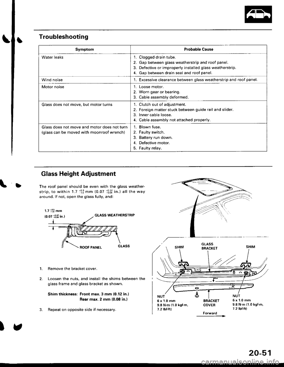
The roof panel should be even with the glass weather-
strip, to within 1.7 :lr3 mm (0.07 :3:31 in.) all the way
around. lf not, open the giass fully, and:
GLASS WEATHERSTRIP
1. Remove the bracket cover.
Loosen the nuts, and install the shims between the
glass frame and glass bracket as shown.
Shim thickness: Front max.3 mm 10,12 in.l
Rear max. 2 mm 10.08 in.)
Repeat on opposite side i{ necessary.
)
5x1.0mm9.8 N.m 11.0 kgf m,7.2 rbtft)
SRACKETCOVEB
----------1>
6x1.0mm9.8 N.m {1.0 kgtm,7.2 tbf.ft)
1.7 tl.8 mm
{0.07 :3 3i in.}
20-51
Page 1285 of 2189
L
L
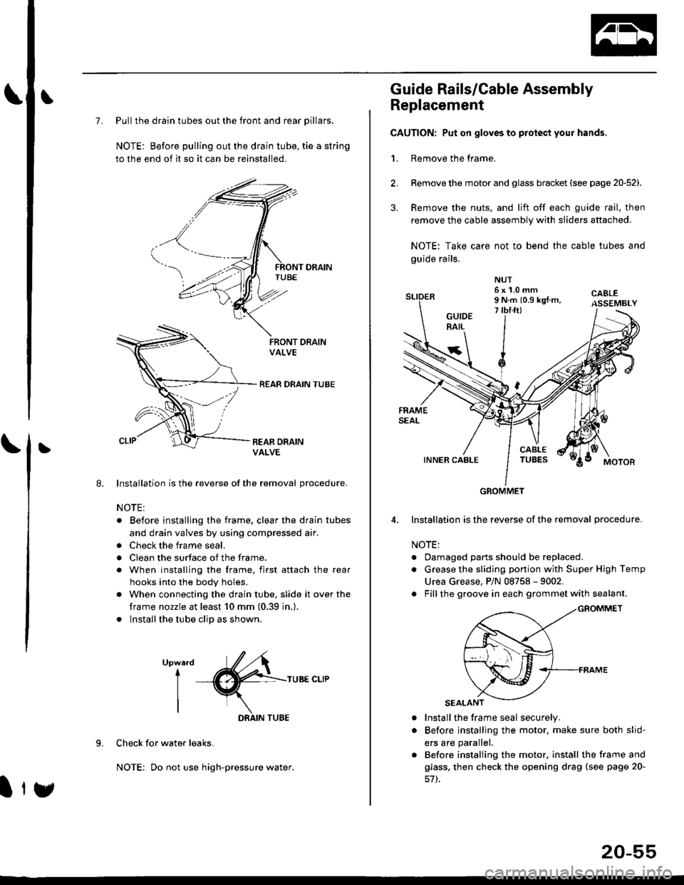
7. Pull the drain tubes out the front and rear pillars.
NOTE: Before pulling out the drain tube, tie a string
to the end of it so it can be reinstalled.
Installation is the reverse of the removal procedure.
NOTE:
. Before installjng the frame, clear the drain tubes
and drain valves by using compressed air.
. Check the frame seal.
. Clean the surface of the frame.
. When installing the frame, first attach the rear
hooks into the body holes.
. When connecting the drain tube, slide it over the
frame nozzle at least 10 mm (0.39 in.).
. Install the tube clip as shown.
UpwardI
I
I
TUBE CLIP
Check for water leaks.
NOTE: Do not use high-pressure water.
DRAIN TUBE
Ity
20-55
Guide Rails/Cable Assembly
Replacement
CAUTION: Put on gloves to protect your hands,
1. Remove the frame.
Remove the motor and glass bracket (see page 20-52).
Remove the nuts, and lift off each guide rail, then
remove the cable assembly with sliders attached.
NOTE: Take care not to bend the cable tubes and
guide rails.
Installation is the reverse of the removal procedure.
NOTE:
. Oamaged parts should be replaced.
. Grease the sliding portion with Super High Temp
Urea Grease, P/N 08758 - 9002.
. Fillthe groove in each grommet with sealant.
a
a
Install the frame seal securely.
Before installing the motor. make sure both slid-
ers are parallel.
Before installing the motor. install the frame and
glass, then check the opening drag (see page 20-
GROMMET
Page 1319 of 2189
Rear seal belt removal (3Dl:
1. Remove:
. Rear seat-back and rear seat cushion (see page
20_80)
. Rear center shelf and rear side shelf (see page
20_60)
. Rear trim panel and side trim panel (see page 20
60)
2. Remove the upper anchor cover
UPPER ANCHOR BOLT7/16-20 UNF32 N.m {3.3 kgf.m,2it lblft)
UPPERANCHOR
RETRACTOR
RETRACTOR BOLT7/16-20 UNF32 N.m 13.3 kgl.m.24 tbf.ft)
REAR SEATBELT
LOWEF
3.
7/r6-20 UNF32 N.m {3.3 kgl.m. 24 lbf.ftl
Remove all the anchor bolts and retractor bolt. then
remove the rear seat belt and retractor.
4. Installation is the reverse of the removal procedure.
NOTE:
. Check that the retractor locking mechanism func
tions as described on page 20-91.
. Make sure you assemble the washers and collars
on the upper anchor bolt as shown.
. Betore installing the anchor bolt, make sure there
are no twists or kinks in the rear seat belt.
Upper snchor boh construction:
COLLARS
Lower anchor bolt construction:
LOWER ANCHOR
TOOTHEDLOCK WASHER
(cont'd)
20-89
Page 1352 of 2189
Body ('97 model)
Front Seat Belt
Removal/lnstallatlon ....20-128
Rear Seat
RemovaUlnstallation ....20-126
Washer Tube
Windshield
fndex .......... 20-124
Outline of '97 Model Changes
The molding side seal was added.
The method of installing the rear seat cushion was changed (2Dl3D).
A middle floor gusset was added and the method of detaching the seat belt retractor was changed (2Dl3D)
The installation position of the washer tube was changed.
Page 1371 of 2189
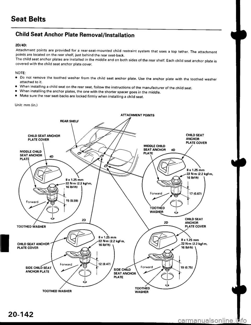
Seat Belts
Child Seat Anchor Plate Removal/lnstallation
2DllDl
Attachment points are provided for a rear-seal-mounted child restraint system that usespoints are located on the rear shelf, tust behind the rear seat-back.The child seat anchor plates are installed in the middle and on both sides of the rear shelf.covered with the child seat anchor olate cover.
a top tether. The attachment
Each child seat anchor plate is
NOTE:
' Do not remove the toothed washer from the child seat anchor plate, Use the anchor plate with the toothed washerattached to it.
. When installing a child seat on the rear seat, follow the instructions of the manufacturer of the child seat.. When installing the anchor plates, the one with the shoner spacer goes in the middle.. Make sure the rear seat-backs are locked firmly when installing a child seat.
Unit: mm (in.)
REAR SHELF
CIIILD SEAT ANCHORPLATE COVER
MIDOLE CHILDSEAT ANCHOR
CHILO SEATANCHORPLATE COVER
CHILD SEATANCHORPLATE COVER
8 x 1.25 mm22 N.m 12.2 kgl m,
PLA
8 x 1.25 mm22 N.m 12.2 kgl.m,
I x 1.25 mm22 N.m 12.2 kgl.m,16 tbt.ftt
17 {0.67)
16 tbf.ft)
15 {0.s9)
WASHER
rl)
.t
TOOTHEO
ll ff*,".rd,',i"'"o*
SIDESEAT
I x 1,25 mmN.m {2.2 kgf.m.16 tbtftl
SIDE
16 tbf ftl
ANCHOR PLATESEAT ANCHORPLATE
ATTACHMENT POINTS
torward .
20-142
TOOTHED
12lO.47l19 (0.75)
Page 2189 of 2189
Connector ldentification and Wire Harness Routing
Connector
ot
Terminal
Numbor ot
CavitiesLocationConnects toNotest
t
Fuel Sub-Harness (GX)
uc/c
c682
c683
c684
6-GRN
2-GRY
3-N/A
2-GRY
Behind left side of rear seal
Left side of trunk
Middle ot trunk
Middle of trunk
Floor wire harness
Fuel lank internal solenoid valve
Fuel lank oressure sensor
Fuel tank temoerature sensor
FUEL SUB.HARNESS
203-48
Page:
< prev 1-8 9-16 17-24