1999 HONDA CIVIC height
[x] Cancel search: heightPage 571 of 2189
Glutch Pedal
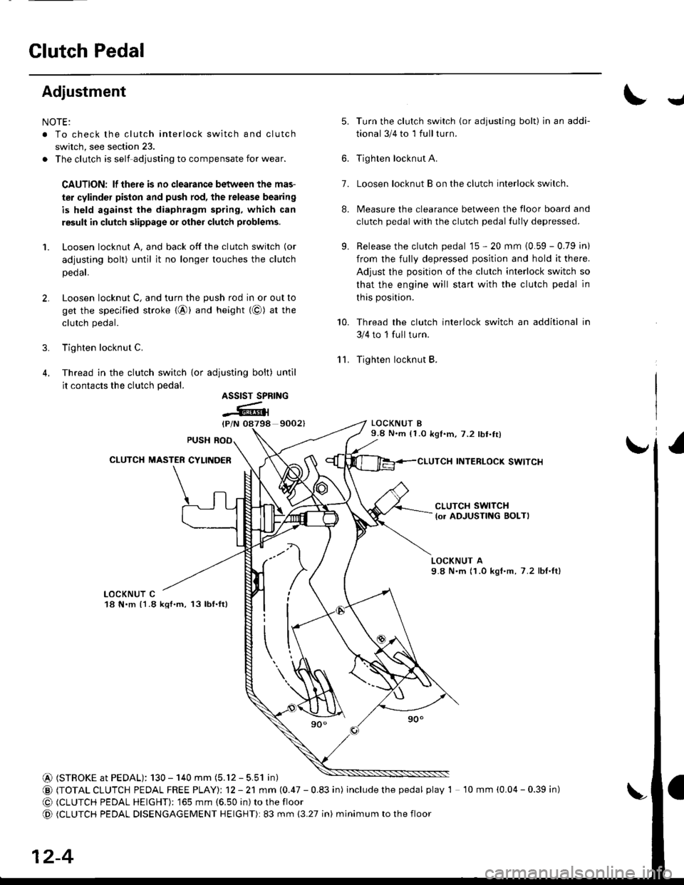
Adjustment
NOTE:
. To check the clutch interlock switch and clutch
switch, see section 23.
. The clutch is self-adjusting to compensate for wear.
CAUTION: lf there is no clearance between the mas-
ter cylinder pislon and push rod, the release bearing
is held against the diaphragm spring, which can
result in clutch slippage 01 other clutch problems.
1. Loosen locknut A, and back off the clutch switch (or
adjusting bolt) until it no longer touches the clutch
peoar.
2. Loosen locknut C, and turn the push rod in or out to
get the specified stroke {@} and height (@) at tne
clutch pedal.
3. Tighten locknut C.
4. Thread in the clutch switch {or adiusting bolt) until
it contacts the clutch pedal.
9002)
Turn the clutch switch (or adjusting bolt) in an addi-
tional 3/4 to 1 full turn.
Tighten locknut A.
Loosen locknut B on the clutch interlock switch.
Measure the clearance between the floor board and
clutch pedal with the clutch pedal fully depressed.
Release the clutch pedal 15 - 20 mm {0.59 - 0.79 in)
from the fully depressed position and hold it there.
Adjust the position of the clutch interlock switch so
that the engine will start with the clutch pedal in
this position.
Thread the clutch interlock switch an additional in
3/4 to 1 full turn.
Tighten locknut B.
LOCKNUT B9.8 N.m (1.0 k91.m,7.2 lbt.tt)
INTERLOCK SWITCI{
J
'lL
5.
7.
8.
9.
10.
ASSIST SPRING
-Atl
CLUTCH SWITCH
lo. ADJUSTING BOLTI
LOCKNUT A9.8 N'm (1.0 kgI.m, 7.2 lbf,ft)
LOCKNUT C18 N.m {1.8 kql.m, 13lbf.ft}
@ (STROKE at PEDAL): 130 - 140 mm (5.12 - 5.51 in)
@ (TOTAL CLUTCH PEDAL FREE PTAYI: 12 - 21 mm (0.47 - 0.83 in) includethepedal play 1 10 mm (0.04 - 0.39 in)
@ (CLUTCH PEDAL HEIGHT): '�]65 mm {6.50 in) to the floor
@ (CLUTCH PEDAL DISENGAGEMENT HEIGHT): 83 mm (3.27 in) minimum to the floor
12-4
Page 574 of 2189
Pressure Plate
\Removal/lnsPection
1.Inspect the fingers of the diaphragm spring for wear
at the release bearing contact area.
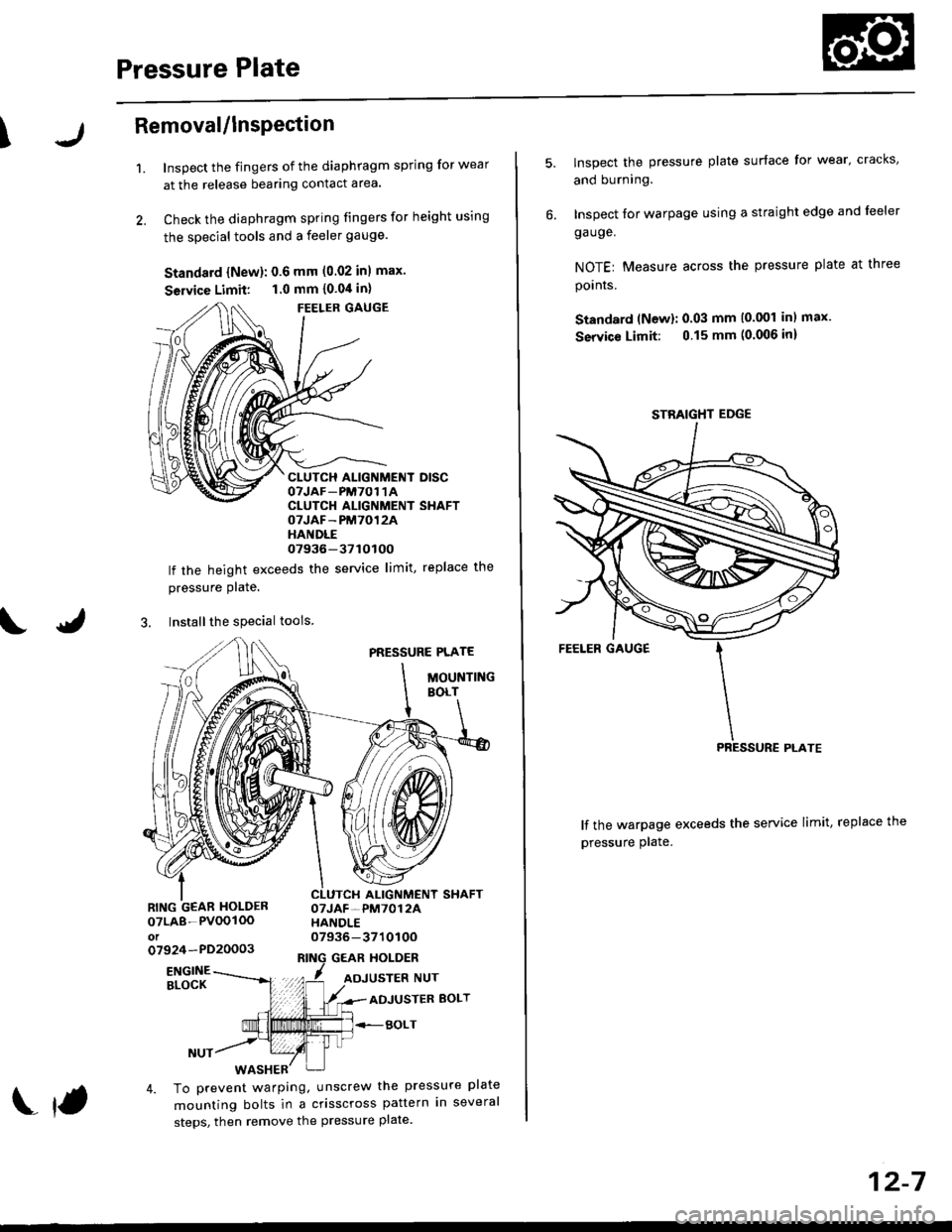
Check the diaphragm spring fingers for height using
the special tools and a feeler gauge.
Standard {New}: 0.6 mm (0.02 inl max.
Seruice Limit: 1.0 mm {0.04 in}
FEELER GAUGE
CLUTCH ALIGNMENT DISCOTJAF_PM7O1 1ACLUTCH ALIGNMENT SHAFTOTJAF-PM7012AHANDLE07936-37tOtOO
lf the height exceeds the service limit, replace the
pressure Plate.
3. Installthe special tools
PRESSURE PLATE
MOUNTINGBOLT
ALIGNMENT SHAFTOTJAF-PM7012AHANDLE07936-371010Oo7924-PD20003GEAR HOLDER
07LA8-PVOOIOOot
ENGINEBLOCKADJUSTER BOLT
BOLT
4. To prevent warping, unscrew the pressure plate
mounting bolts in a crisscross pattern in several
steps, then remove the pressure plate.
f
12-7
lnspect the pressure plate surface for wear' cracks,
and burning.
Inspect for warpage using a straight edge and leeler
ga uge.
NOTEr Measure across the pressure plate at three
pornrs.
Standard (Newl: 0.03 mm (0.001 inl max.
Service Limit: 0.15 mm (0.006 inl
lf the warpage exceeds the service limit, replace the
pressure plate.
STBAIGHT EDGE
Page 616 of 2189
Mainshaft Thrust Shim
Adjustment
Remove the thrust shim and oil
the transmission housing.
1.gu ide plate from
THRUST SHIM
OIL GUIDEPLATE
TBANSMISSIONHOUSING
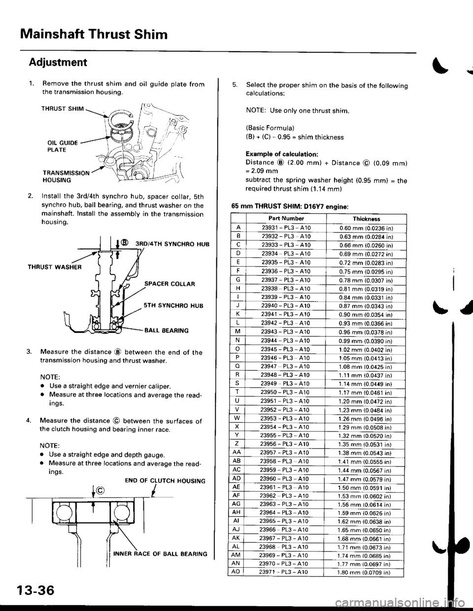
Install the 3rd/4th synchro hub, spacer collar, 5th
synchro hub, ball bearing, and thrust washer on themainshaft. Install the assembly in the transmission
h ousing.
@ gnol+lx syNcHRo HUB
THRUST WASHER
SPACER COLLAR
4.
Measure the distance @ between the end of thetransmission housing and thrust washer.
NOTE:
. Use a straight edge and vernier caliper.. Measure at three locations and average the read-
Ings.
Measure the distance @ between the surfaces ofthe clutch housing and bearing inner race.
NOTE:
. Use a straight edge and depth gauge.
. Measure at three locations and average the read-
Ings.
sTH SYNCHRO IIUB
BALL EEARING
CLUTCH
L
HOUSINGENO OF
13-36
INNER RACE OF BALL AEARING
\
5.Select the proper shim on the basis of the followingcalculations:
NOTE: Use only one thrust shim.
(Basic Formula)(B) + {C). 0.95 = shim thickness
Example of calculation:
Distance @ (2.00 mm) + Distance @= 2.09 mm
subtract the spring washer height (0.95
required thrust shim (1.14 mm)
65 mm THRUST SHIM: D16Y7 engine:
(0.09
mm)
mm)
= tne
r1
Part NumborThickness
23931 - PL3 A100.60 mm (0.0236 in)23932 - PL3 A100.63 mm 10.0284 in)c23933 - PL3 A100.66 mm {0.0260 iniD23934 PL3 - A100.69 mm (0.0272 in)
E23935-PL3-4100.72 mm 10.0283 in)
F23936-PL3-4100.75 mm 10.0295 in)G23937-PL3-A100.78 mm {0.0307 in}
23938 PL3 - A100.81 mm (0.0319 in)I23939 - PL3 At00.84 mm (0.0331 in)J23940-PL3-Ar00.87 mm (0.0343 in)
23941 - PL3 - A100.90 mm (0.0354 in)
L23942 - PL3 A100.93 mm (0.0366 in)
23943-PL3-A100.96 mm (0.0378 in)N23944 PL3 - A100.99 mm 10.0390 in)
o23945-PL3-A101.02 mm {0.0402 in}23946 - PL3 A101.05 mm (0.0413 in)o23947 PL3 - 4101.08 mm (0.0425 in)R23948-PL3-A101.11mm (0.0437 in)s23949 PL3 - A101.14 mm {0.0449 in}T23950-PL3-A101.17 mm (0.0461 in)
U23951 PL3 - A101.20 mm (0.0472 in)
23952-PL3-Ar01.23 mm {0.0484 in)
23953-PL3-A101.26 mm {0.0496 in}X23954 - P13, A101.29 mm (0.0508 in)23955 - PL3 A101.32 mm (0.0520 in)z23956-PL3-Ar01.35 mm {0.0531 in)
23957-PL3-A101.38 mm (0.0543 in)
AB239s8 - PL3 A101.41 mm (0.0555 in)AC23959 PL3 - A101.44 mm (0.0567 in)
AD23960 - PL3 A101.47 mm (0.0579 in)23961 - PL3 4101.50 mm (0.0591 in)23962 PL3 - A101.53 mm (0.0602 in)AG23963-PL3-4101.56 mm (0.0614 in)AH23964 - PL3 A101.59 mm (0.0626 in)AI23965-PL3-A101.62 mm {0.0638 in)
23966 PL3 - A101.65 mm (0.0650 in)AK23967-PL3-A101.68 mm {0.0661 in)
23968 PL3 - A101.71 mm {0.0673 in)23969-PL3-A101.74 mm (0.06a5 iniAN23970- PL3 -A101.77 mm (0.0697 in)AO23971 - PL3 - A101.80 mm 10.0709 in)
Page 862 of 2189

Transmission
Installation (cont'dl
9. Attach the torque converter to the drive plate witheight drive plate bolts and torque as follows:Rotate the crankshaft pulley as necessary to tightenthe bolts to 1/2 of the specified torque. then to thefinal torque, in a crisscross pattern.
After tightening the last bolt, check that the crank-shaft rotates freely.
TOROUE: 12 N.m {1.2 kgl.m, 8.7 tbt{r}
10 x 1.25 mm
6x1.0mm12 N.m (1.2 kgt m,8.7 rbt ft)
I 1.25 mm2/t N.m {2.4 kg{.m,17 tbt ftlCONVERTEB
10. Install the torque convener cover and the €nginestiffener.'11. Tighten the crsnkshaft pull€y bolt, if necessary (see
section 61.
12. Connect the ATF cooler hoses to the ATF cooler lines(see page 1,t192).
ATF COOIIRUNE
10 x 1.25 mma,l N.m {4.5 kgl.m,33 rbt.fttRIGHT FRONT 12 x 1.25 mmMOUNT/BRACKET 6.t N.m (6.5 kg{.m,47 tbt ftl
13. Install the right front mounvbracket.
4,r N.m 14.5 kgf.m,33 lbtft)
COVER
L,
14-1A4
SHIFT CABLE
SHIFT CAAE COVER
14. Install the control lever with a new lock washer tothe control shaft, then install the shift cable cover.
CAUION: Taks care not to bend the shift cable.
L(rcK WASHERReplace.
8 x 1,25 r'|m22N-m12.2 tgt m. 16lbnftl
x 1.0 mmtit N.m 11.4 kgt m,10 tbr,ft,
15. lnstall the exhaust pipe A.
NOTE: D16Y8 engine is shown; D16y/ engine is sim_ilar.
Replace.
GASKETReplace.
SELF.LOCKING NUTReplace.10 x 1.25 mm54 N.m (5.5 lgf.m,40 tbt ftl
NUTSELF.LOCKING NUTReplace.8 x 1.25 mm22 N.m {2.2 kgl.m, 16lbtfrl
Replace.8 x 1.25 mm16 N.m {1.6 kgI.m,12 tbf.ft)
Page 1045 of 2189
Driveshafts
Reassembly (cont'dl
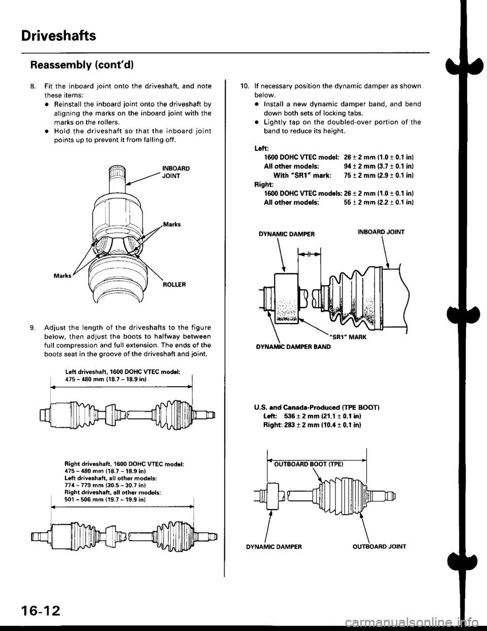
8. Fit the inboard joint onto the driveshaft, and note
these items:
. Reinstall the inboard joint onto the driveshaft by
aligning the marks on the inboard joint with the
marks on the rollers.
. Hold the driveshaft so that the inboard joint
points up to prevent it from falling off.
Adjust the length of the driveshafts to the figure
below, then adjust the boots to halfway between
full comDression and full extension. The ends of the
boots seat in the groove of the driveshaft and joint.
Right driveshaft, 1600 OOHC VTEC model:475 - 480 mm (18.7 - 18.9 in)Left driveshaft, all othei models:774-779 mm (30.5 - 30.7 in)Right driveshaft, all other models:501 - 506 mm 119.7 -'19.9 inl
Left driveshaft. 1600 DOHC WEC model:475 - 480 mm 118.7 - 18,9 inl
16-12
OYNAMIC DAMPEROUTBOARD JOINT
10. lf necessary position the dynamic damper as shown
Detow.
. Install a new dynamic damper band. and bend
down both sets of locking tabs.
. Lightly tap on the doubled-over ponjon of the
band to reduce its height.
Loft:
1600 DOHC VTEC model: 26 i 2 mm (1.0 t 0.1 inl
All other models: 9,1t 2 mm (3.7 10.1 inl
With "SR1" mark: 7512 mm 12.9 ! 0.1 inl
Right:
16dl DOHC VTEC models: 2612 mm 11.0 t 0.1 inl
All other modelii
DYNAMIC DAMPER
-SR1" MARK
U.S. and Canada-Produced ITPE BOOTI
Left 53612 mm {21.1 10.1 in}
Right: 2txt 12 mm {10.it 1 0.1 in}
5512 mm (2.2 t 0.1 inl
INBOARO JOINT
DYNAMIC DAMPER BAND
Page 1068 of 2189
Steering Gearbox
Reassembly (cont'd)
21.
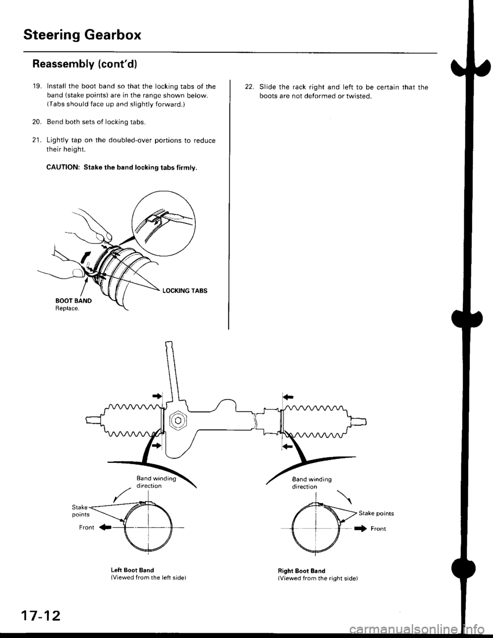
'19.
20.
Install the boot band so that the locking tabs of the
band (stake points) are in the range shown below.
{Tabs should face up and slightly forwaro.,
Bend both sets of locking tabs.
Lightly tap on the doubled-over portions to reduce
their height.
CAUTION: Stake the band locking tabs firmly.
22. Slide the rack right and left to be certain that the
boots are not detormed or twisted.
Stake points
+ Fronr
Lett Boot Band(Viewed from the left side)Right Boot Bend(Viewed from the right side)
17-12
Page 1120 of 2189
Steering Gearbox
Reassembly (cont'dl
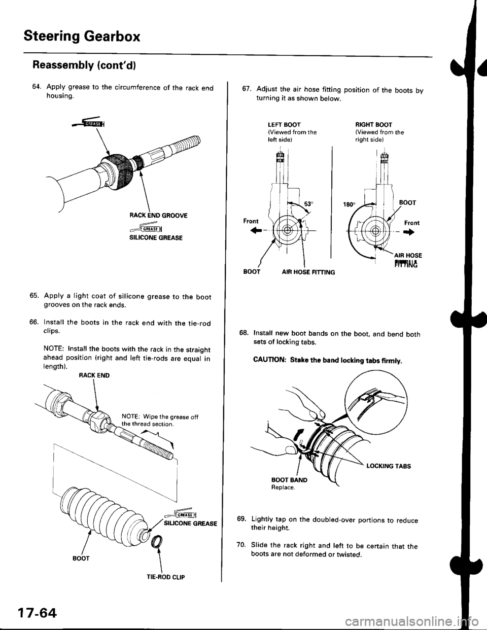
64. Apply grease to the circumference of the rack endhousing.
RACK END GROOVE
=^.#-q!:s!!H
SILICONE GREASE
Apply a light coat of silicone grease to the bootgrooves on the rack ends.
lnstall the boots in the rack end with the tie-rodclips.
NOTE: Install the boots with the rack in the straightahead position (right and left tie-rods are equal inlength).
66.
RACK END
NOTE: Wipe the grease offthe thread section.
17-64
TIE.ROD CLIP
67. Adjust the air hose fitting position of the boots bvturning it as shown below.
LEFT BOOT(Viewed from theleft side)
RIGHT BOOT{Viewed from theright side)
AIR HOSE FITTING
Install new boot bands on the boot, and bend bothsets of locking tabs.
CAUTION: Stlke ths band locking tabs firmly.
Lightly tap on the doubled-over portions to reducetheir height.
Slide the rack right and left to be certain that theboots are not deformed or twisted.
Page 1159 of 2189
)
Brake Pedal
Pedal Height
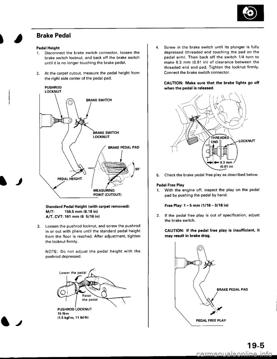
1. Disconnect the brake switch connector, loosen the
brake switch locknut, and back off the brake switch
until it is no longer touching the brake pedal,
2. At the carpet cutout, measure the pedal height from
the right side center of the pedal pad.
PUSHRODLOCKNUT
Standard Pedal Height (with carpet removed):
M/T: 156.5 mm 16.16 inl
A/T, CVT: 161 mm (5 5/16 in)
3. Loosen the pushrod locknut, and screw the pushrod
in or out with pliers until the standard pedal height
from the floor is reached. After adjustment, tighten
the locknut firmly.
NOTE: Do not adiust the pedal height with the
Dushrod depressed.
It
PUSHROO LOCKNUT15 N.m(1.5 kgf.m. 11 lbI.ft)
POINT ICUTOUTI
4. Screw in the brake switch until its plunger is fully
depressed (threaded end touching the pad on the
pedal arm). Then back off the switch 1/4 turn to
make 0.3 mm (0.01 in) of clearance between the
threaded end and pad. Tighten the locknut firmly.
Connect the brake switch connector.
CAUTION: Make sure that the brake lights go off
when the pedal is released.
LOCKNUT
5. Check the brake pedal free play as described below.
Pedal Free Plsy
1. With the engine off, inspect the play on the pedal
pad by pushing the pedal by hand.
Free Play: 1 - 5 mm (1/16 - 3/16 inl
2. lf the pedal free play is out of specitication, adjust
the brake switch.
CAUTION: lf the pedal free play is insufficient, it
may result in brake drag.
BRAKE PEDAL PAO
)
19-5
*0.3 mm(0.01 in)