Page 1144 of 2189
Front Damper
Installation (cont'd)
2. Install the damper fork over the driveshaft and onto
the lower arm. Install the front damper into the
damper fork so the aligning tab is aligned with the
slot in the damper fork.
ALIGNING TAB
DAMPERPINCHEOLT10 x 1.25 mm43 N.m 14.4 kgf.m, 32 lbtftl12 x 1.25 mm64 N.m 16.5 kgl.m, 47 lbtftlReplace.
Loosely install the damper pinch bolt into the top ofthe damper fork.
Loosely install the damper fork bolt and a new self-locking nut into the bottom of the damper fork.
Raise the knuckle with a floor jack until the vehiclejust lifts off the safety stand.
@E The ftoor ilck must be sscuroty posi-
lionsd or personal iniury may r€€uh.
Tighten the damper pinch bolt.
Tighten the damper fork bolt and self-locking nut.
Tighten the flange nuts on top of the damper.
Install the brake hose mounts with the brake hose
mounting bolts.
Install the front wheel.
7.
8.
9.
10.
1a-20
Page 1162 of 2189
Front Brake Pads
Inspection and Replacement
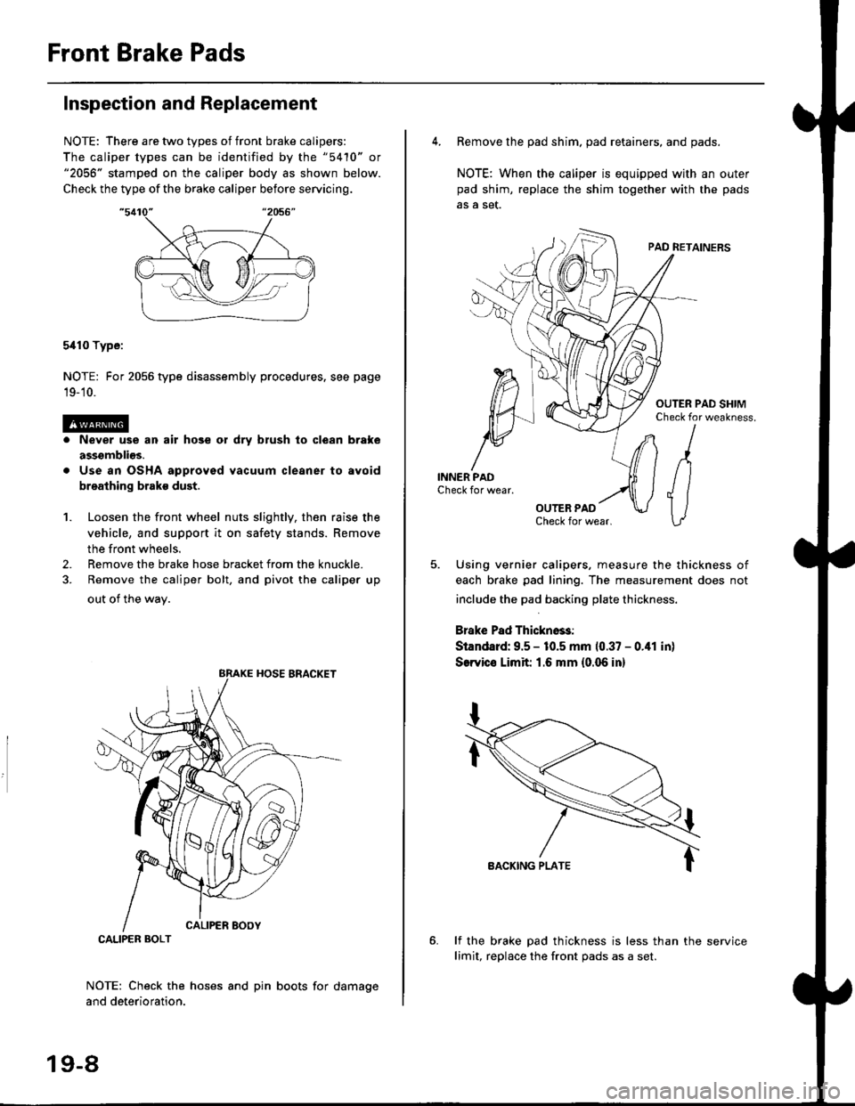
NOTE: There are two types of front brake calipers:
The caliper types can be identified by the "5410" or"2056" stamped on the caliper body as shown below.
Check the type of the brake caliper before servicing.
5i110 Type:
NOTE: For 2056 type disassembly procedures. see page
19-'10.
Never use an air hose or dry brush lo clean brake
assgmblios.
Use an OSHA approved vacuum cleaner to avoid
breathing brake dust.
Loosen the front wheel nuts slightly, then raise the
vehicle, and support it on safety stands. Remove
the front wheels.
Remove the brake hose bracket from the knuckle.
Remove the caliper bolt, and pivot the caliper up
out of the wav.
1.
2.
NOTE: Check the hoses and pin boots for damage
and deterioration.
CALIPER BOLT
19-8
4. Remove the pad shim. pad retainers, and pads.
NOTE: When the caliper is equipped with an outer
pad shim, replace the shim together with the pads
5. Using vernier calipers, measure the thickness of
each brake pad lining. The measurement does not
include the pad backing plate thickness.
Brake Pad Thickno$:
Standard: 9.5 - 10.5 mm 10.37 - 0.41 in)
SerYico Limit 1.6 mm {0.06 in}
lf the brake pad thickness is less than the service
limit, replace the front Dads as a set.
Page 1163 of 2189
)
It
7. Clean the caliper thoroughly; remove any rust, and
check for grooves and cracks.
8. Check the brake disc for damage and cracks.
9. lnstall the pad retainers,
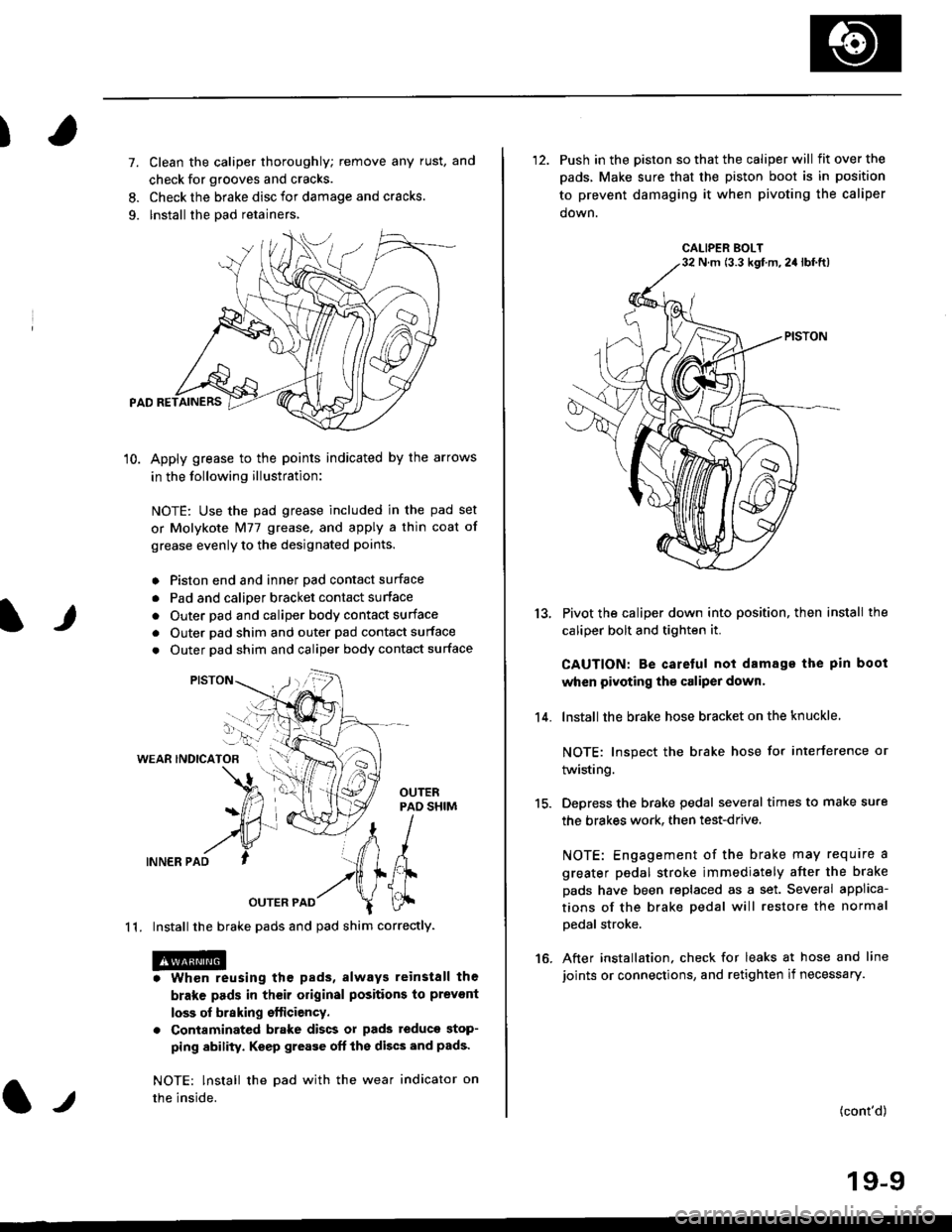
10. Apply grease to the points indicated by the arrows
in the following illustration:
NOTE: Use the pad grease included in the pad set
or Molykote Nl77 grease, and apply a thin coat of
grease evenly to the designated points.
o Piston end and inner Dad contact surface
. Pad and calioer bracket contact surface
. Outer pad and caliper body contact surface
. Outer pad shim and outer pad contact surface
. Outer pad shim and caliper body contact surface
WEAR INDICATOB
INNER PAD
OUTER PAD
1 1. Install the brake pads and pad shim correctly.
. Whon reusing the pads, always reinstall the
brake pads in their original positions to prevont
loss of braking efticiency.
. Contaminated brake discs or pads teduce stop-
ping ability. Keep grease oft the discs and pads'
NOTE: lnstall the Dad with the wear indicator on
the inside.l.t
'12. Push in the piston so that the caliper will fitoverthe
pads, Make sure that the piston boot is in position
to prevent damaging it when pivoting the caliper
down.
Pivot the caliper down into position, then install the
caliper bolt and tighten it.
CAUTION: Be caretul not damage the pin boot
when pivoting the caliper dowr.
lnstall the brake hose bracket on the knuckle
NOTE: Inspect the brake hose for interference or
twisting.
Depress the brake pedal several times to make sure
the brakes work. then test-drive.
NOTE: Engagement of the brake may require a
greater pedal stroke immediately after the brake
pads have been replaced as a set. Several applica-
tions of the brake pedal will restore the normal
Dedal stroke.
After installation. check for leaks at hose and line
joints or connections, and retighten if necessary.
13.
14.
15.
16.
(cont'd)
19-9
CALIPER BOLTN m (3.3 kgf m,2a lbf.ft)
Page 1164 of 2189
Front Brake Pads
2056 Type:
@. Never use an air hose or dry brush to clgan brake
assemblies.
. Use an OsHA-approved vacuum cleanor lo avoid
breathing broke dust.
Inspection and Replacement (cont'dl
1. Loosen the front wheel nuts slightly. then raise the
vehicle, and support it on safety stands. Remove
the front wheels.
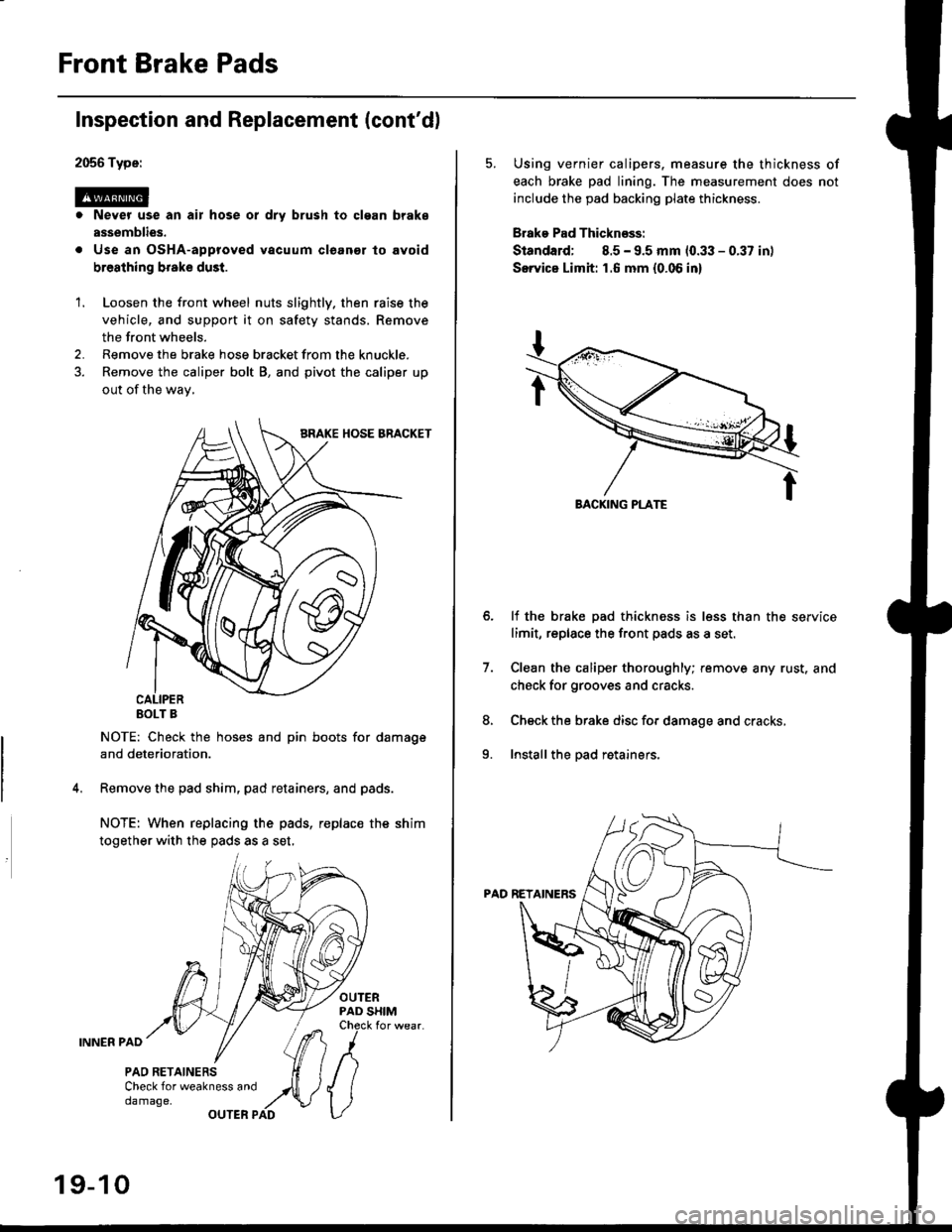
2. Remove the brake hose bracket from the knuckle.
3. Remove the caliper bolt B, and pivot the caliper up
out of the wav,
EOLT B
NOTE: Check the hoses and pin boots for damage
and deterioration.
Remove the pad shim, pad retainers, and pads.
NOTE: When replacing the pads, replac€ the shim
together with the pads as a set,
OUTERPAD SHIMCheck for wear.
INNER PAD
PAO RETAINERSCheck for weakness anddamage,OUTER PAD
19-10
5. Using vernier calipers. measure the thickness of
each brake pad lining. The measurement does not
include the pad backing plate thickness.
Brake Pad Thicknsss:
Standard; 8.5 - 9.5 mm 10.33 - 0.37 in)
Servica Limh: 1.6 mm {0.06 in}
lf the brake pad thickness is less than the service
limit, replace the front pads as a set,
Clean the caliper thoroughly; remove any rust. and
check for grooves and cracks.
Check the brake disc for damage and cracks,
Install the pad retainers.
7.
8.
9.
Page 1165 of 2189
)
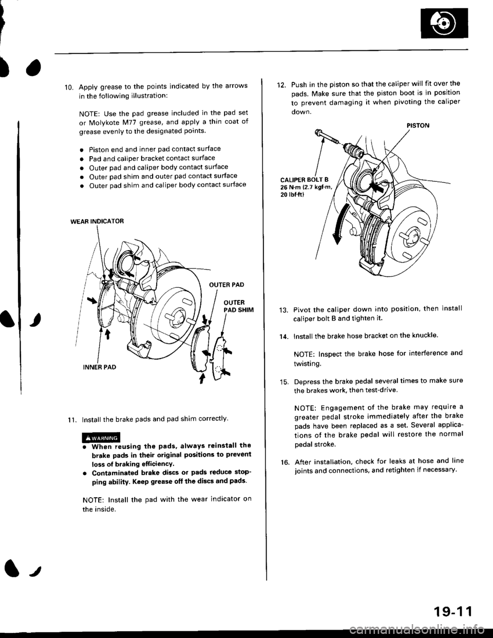
lO. Apply grease to the points indicated by the arrows
in the following illustration:
NOTE: Use the pad grease included in the pad set
or Molykote M77 grease, and apply a thin coat of
grease evenly to the designated points.
. Piston end and inner pad contact surface
o Pad and caliper bracket contact surface
. Outer pad and caliper body contact surface
. Outer pad shim and outer pad contact surface
. Outer pad shim and caliper body contact surface
OUTER PAD
OUIERPAD SHIM
I 1. Install the brake pads and pad shim correctly
@o When reusing the pads, always reinstall the
brake pads in their original positions to plevent
loss of braking etticiencY.
. Contaminated brake discs ol pads reduce stop-
ping ability. Keep grease oft the discs and pads.
NOTE: Install the pad with the wear indicator on
the inside.
WEAR INDICATOR
12. Push in the piston so that the caliper will fit over the
pads. Make sure that the piston boot is in position
to prevent damaging it when pivoting the caliper
CALIPER BOLT B26 N.m {2.7 kgt m,
20 rbl.ftl
14.
13.Pivot the caliper down into position, then install
caliper bolt B and tighten it.
lnstallthe brake hose bracket on the knuckle.
NOTE: Inspect the brake hose for interference and
twisting.
Depress the brake pedal several times to make sure
the brakes work, then test-drive
NOTE: Engagement of the brake may require a
greater pedal stroke immediately after the brake
pads have been replaced as a set. Several applica-
tions ot the brake pedal will restore the normal
pedal stroke.
After installation, check for leaks at hose and line
joints and connections, and retighten if necessary.16.
PISTON
19-1 1
Page 1194 of 2189
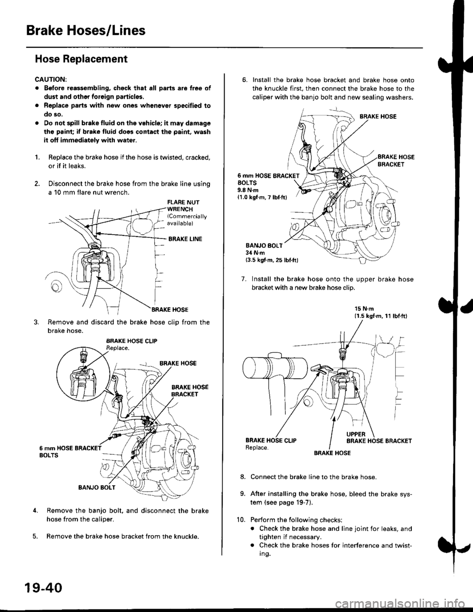
Brake Hoses/Lines
Hose Replacement
CAUTION:
. Bgfore reagsembling, chgck that all parts are free of
dust and othor foroign particles.
. Repl8ce parts with new ones whenever specified to
do so,
. Do not spill brake fluid on th6 vehicle; it may damage
tho paint; if brake fluid does contact the paint, wash
it off immediately with water.
1.Replace the brake hose if the hose is twisted, cracked,
or if it leaks.
Disconnect the brake hose from the brake line using
a 10 mm flare nut wrench.
FLARE NUTWRENCHlCommerciallyava ilable)
BRAKE LINE
BRAKE HOSE
Remove and discard the brake hose cliD from the
brake hose.
Remove the banjo bolt, and disconnect the brake
hose from the caliper.
Remove the brake hose bracket from the knuckle.
19-40
10.
6. Install the brake hose bracket and brake hose onto
the knuckle first. then connect the brake hose to the
caliper with the banjo bolt and new sealing washers.
BRAKE HOSE
6 mm HOSE BRACKETBOLTS9.8 N.m{1.0 kgf m, 7 lbtfr}
BANJO BOI.T34 N.m{3.5 kgf.m,25 lbt.ftl
7. Install the brake hose onto the uooer brake hose
bracket with a new brake hose clip
15 N.m(1.s ks{.m, 11 lbl.ftl
Connect the brake line to the brake hose.
After installing the brake hose, bleed the brake sys-
tem (see page 19-7).
Perform the following checks:
. Check the brake hose and line joint for leaks, and
tighten if necessary.
. Check the brake hoses for interference and twist-
I ng.
8.
Page:
< prev 1-8 9-16 17-24