Page 148 of 2189
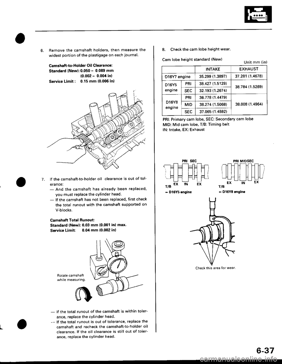
6, Remove the camshaft holders. then measure the
widest ponion of the plastigage on each journal.
Camshaft-to-Holder Oil Clearance:
Standard lNew):0.050 - 0.08!t mm
{0.002 - 0.004 in}
Service Limit : 0.15 mm {0.006 in)
lf the camshaft-to-holder oil clearance is out ot tol-
erance:- And the camshaft has already been replaced,
you must replace the cylinder head.
- lf the camshaft has not been replaced, first check
the total runout with the camshaft supported on
V-blocks.
Camshaft Total Runout:
Standard (New): 0.03 mm (0.001 inl max.
Service Limit: 0.04 mm {0.(X)2 in)
-7.
Rotate camshattwhile measuring.
L
- lf the total runout of the camshaft is within toler-
ance, replace the cylinder head.
- lf the total runout is out of tolerance, replace the
camshaft and recheck the camshaft-to-holder oil
clearance. lf the oil clearance is still out of toler-
ance. replace the cylinder head.
INTAKEEXHAUST
O16Y/ engine35.299 (1.3897)37.281 (1.4678)
D16Y5
engrne
PRI38.427 11.5129138.784 (1.5269)
SEC32.193 (1.2674)
D l6Y8
engrne
PRI36.77811.44791
38.008 (1.4964)MID38.274 (1.5068)
sEu37.065 (1.4592)
8. Check the cam lobe height wear.
Cam lobe height standard (New)
t/g a* rN Ex
- D16Y5 engine
PRI; Primary cam lobe, SEC: Secondary cam lobe
MtD: Mid cam lobe. T/B: Timing belt
lN: Intake, EX: Exhaust
PRIsEcMIDSEC
rts
- Dl6YE ongine
Unit mm (in)
Check this area {or wear.
6-37
Page 151 of 2189
Cylinder HeadValve Seats
Warpage
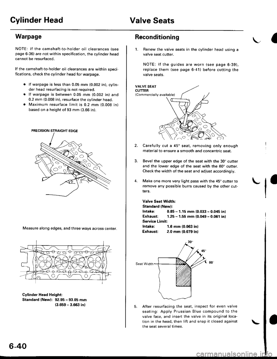
NOTE: lf the camshaft-to-holder oil clearances (see
page 6-36) are not within specification, the cylinder head
cannot be resurfaced.
lf the camshaft-to-holder oil clearances are within sDeci,
fications, check the cylinder head lor warpage.
lf warpage is less than 0.05 mm (0.002 in), cylin-
der head resurfacing is not required.
lf warpage is between 0.05 mm (0.002 in) and
0.2 mm {0.008 in), resurface the cylinder head.
Maximum resurface limit is 0,2 mm (0.008 in)
based on a height of 93 mm (3.66 in).
Measure along edges, and three ways across center.
Cylinder Head Height:
Standard {Newl: 92.95 - 93.05 mm
{3.659 - 3.66:} in)
6-40
\
Reconditioning
'1. Renew the valve seats in the cylinder head using a
valve seat cutter.
NOTE: lf the guides are worn (see page 6-39).
replace them (see page 6-41) belore cutting the
valve seats.
VALVE SEATCUTTER(Commercially available)
2.
?
4.
Carefully cut a 45'seat, removing only enough
material to ensure a smooth and concentric seat.
Bevel the upper edge of the seat with the 30. cutter
and the lower edge of the seat with the 60' cutter.
Check the width of the seat and adjust accordingly.
Make one more very light pass with the 45" cutter to
remove any possible burrs caused by the other cut-
Iers.
Valve Seat Width:
Standard (N€w):
Intake: 0.85 - 1.15 mm 10.033 - 0.045 in)
Exhaust: 1.25 - 1.55 mm {0.049 - 0.061 in}
Sorvice Limit:
Intake: 1.6 mm (0.063 inl
Exhausl: 2.0 mm (0.079 in)
Seat Width
5. After resurfacing the seat, inspect for even valve
seatingr Apply Prussian Blue compound to the
valve face, and insert the valve in its original loca-
tion in the head, then liit and snap it closed against
the seat several times.
Page 153 of 2189

Valve Guides
Replacement (cont'd)
Working from the camshaft side, use the driver andan air hammer to drive the guide about 2 mm (0.1 in)towards the combustion chamber. This will knock offsome of the carbon and make removal easier.
CAUTION:
. Always wear satety goggles or a face shield when
driving valve guides.
. Hold the air hammer directly in line with thevalve guide to prevent damaging the driver.
Turn the head over, and drive the guide out towardthe camshaft side of the head.
VALVE GUIOE ORIVER,5.5 mm07742 - 001 01 00
It a valve guide still won't move, drill it out with a8 mm {5/16 in) bit, then try again.
CAUTION: Drill guides only in extreme cases; you
could damage the cylinder head it the guide breaks.
6. Remove the new guides from the freezer, one at atime, as you need them.
6-42
I7. Apply a thin coat of clean engine oil to the outsideof the new valve guide. Install the guide from thecamshaft side of the head; use the special tool todrive the guide in to the specified insralled height. lfyou have all 16 guides to do, you may have to reheat
the head.
VALVE GUIOEDRIVER,5.5 mm07742 - 0010100
ll
Valve Guide lnstalled Height:
Intake: 17.85 - 18.35 mm (0.703 - 0.722 inl
Exhausi: 18.65 - 19.15 mm (0.734 - 0.754 in)
VALVE GUIDE
Page 155 of 2189
Valves
Camshaft/Rocker Arms and
Camshaft Seal/Pulley
Installation (cont'd)
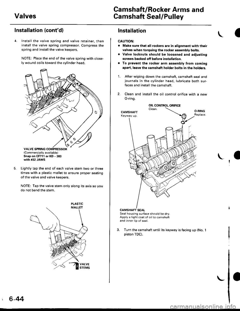
4. Install the valve spring and valve retainer. then
install the valve spring compressor. Compress the
spring and installthe valve keepers.
NOTE: Place the end of the valve spring with close-
ly wound coils toward the cylinder head.
lCornmercially available)Snap-on CFrll or KD - 3tX'with #32 JAWS
Lightly tap the end of each valve stem two or three
times with a plastic mallet to ensure proper seating
of the valve and valve keepers.
NOTE: Tap the valve stem only along its axis so you
do not bend the stem.
' 6-44
Installation
CAUTION:
. Make sure that all tockers are in alignment with their
valvgs when torquing the rocket assembly bolts,. Valve locknuls should be loosened and adiusting
screws backed off bofore installation.
. To prevont tho rocker arm a$smbly from coming
apad, l6av€ the camshaft holder bohs in the holdeB.
1. After wiping down the camshaft, camshaft seal andjournals in the cylinder head, lubricate both sur-
faces and install the camshaft.
2. Clean and install the oil control orifice with a new
O-ring.
CAMSHAFT SEALSeal housing surface should be dry.Apply a light coat of oil to camshaftand inner lip of seal.
3. Turn the camshaft until its keyway is facing up (No.
piston TDC).
OIL CONTROL ORIFICE
Page 156 of 2189

Cylinder Head
4. Apply liquid gasket (Part No. 08718 - 0001 or 08718 -
0003) to the head mating surfaces of the No. 1 and
No.5 camshaft holders.- Apply liquid gasket to the shaded areas
Set the rocker arm assemblY in place and loosely
installthe bolts.- Make sure that the rocker arms are properly posi-
tioned on the valve stems.
Tighten each bolt two turns at a time in the sequence
shown below to ensure that the rockers do not bind
on the valves.
Specitied torquo:
8 mm bolts: 20 N.m (2.0 kgt'm, l/t lbf'ft)
Apply engine oil to the threads.
6 mm bolts: 12 N.m {1.2 kgif'm, 8.7 lbf'ft)
Apply engine oil to the thresds.
6 mm bolts: O, @. @, @
7. Install the back cover. then install the camshaft pul-!
6-45
lnstallation
lnstallthe cylinder head in the reverse order of removal:
NOTE:
. Always use a new head gasket.
. Cylinder head and cylinder block surface must be
clean.
. "UP" mark on the camshaft pulley should be at the top
. Turn the crankshaft so the No. 1 piston is at TDC (see
page 6-20).
. Clean the oil control orifice before installing.
a Do not use the upper cover and lower cover to store
removeo rlems.
Clean the upper cover and lower cover before instal-
taUon.
Cylinder head dowel pins must be aligned.1.
CYUNOER HEAD
PINS
(cont'd)
Page 157 of 2189
Cylinder Head
Installation (cont'dl
Position the camshaft correctly (see page 6-20).
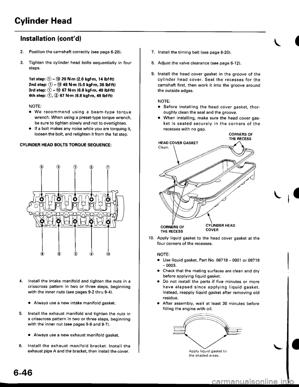
Tighten the cylinder head bolts sequentially in four
steps.
rsr st.p: O - @ 20 N.m (2.0 kgf.m, 14 lbf'ft|
2nd srep: O - @ 49 N.m (5.0 kgf.m, 36 tbtft)
3rd stop; O - @ 67 N.m {6.8 kgf.m, /r9 lbl'ft}
4th st6p: O, O 67 N.m 16.8 kgf.m, 49 tbf.ftl
NOTE:
. We recommend using a beam-type torque
wrench, When using a preset-type torque wrench.
be sure to tighten slowly and not to overtighten.
. If a bolt makesany noisewhileyou aretorquing it,
loosen the bolt, and retighten it from the 1st step,
CYLINDER HEAD BOLTS TOROUE SEOUENCE:
Install the intake manifold and tighten the nuts in a
crisscross pattern in two or three steps, beginning
with the inner nuts (see pages 9-2 thru 9-4).
. Always use a new intake manifold gasket.
Install the exhaust manifold and tighten the nuts in
a crisscross pattern in two or three steps, beginning
with the inner nut {see pages 9-6 and g-7).
. Always use a new exhaust manifold gasket.
Install the exhaust manifold bracket. lnstall the
exhaust pipe A and the bracket, then install the cover.
4.
6-46
\-
(
7.Installthe timing belt (see page 6-20).
Adjust the valve clearance (see page el2),
Install the head cover gasket in the groove of the
cylinder head cover, Seat the recesses for the
camshaft first, then work it into the groove around
the outside edges.
NOTE:
. Before installing the head cover gasket, thor-
oughly clean the seal and the groove.
. When installing, make sure the head cover gas-
ket is seated securely in the corners of the
recesses wath no gap.
COBNERS OFTHE RECESS
CORNERS OFTHE REcEss covEB
Apply liquid gasket to the head cover gasket at the
four corners of the recesses.
NOTE:
. Use liquid gasket, Pan No. 08718 - 0001 or 08718- 0003.
. Check that the mating surfaces are clean and dry
before applying liquid gasket.
. Do not install the parts if five minutes or more
have elapsed since applying liquid gasket.
Instead, reapply liquid gasket after removing old
residue.
. After assembly, wait at least 30 minutes before
filling the engine with oil.
8.
9.
I
10.
Page 158 of 2189
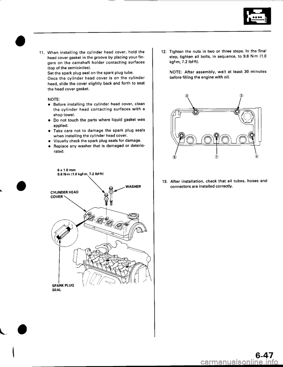
11. When installing the cylinder head cover, hold the
head cover gasket in the groove by placing your fin-
gers on the camshaft holder contacting surfaces
(top of the semicircles)
Set the spark plug seal on the spark plug tube.
Once the cylinder head cover is on the cylinder
head, slide the cover slightly back and forth to seat
the head cover gasket.
NOTE:
. Before installing the cylinder head cover, clean
the cylinder head contacting surfaces with a
shop towel.
. Do not touch the parts where liquid gasket was
aDolied.
. Take care not to damage the spark plug seals
when installing the cylinder head cover,
. Visually check the spark plug seals for damage.
. Replace any washer that is damaged or deterio-
rated.
6x1.0mm9.8 N.m 11.0 ksf.m,7.2lbf ftl
\g-----*o""t'Ptl
veEE
\_
6-47
12. Tighten the nuts in two or thre€ steps. In the final
step, tighten all bolts, in sequence, to 9 8 N'm (1.0
kgf.m, 7.2 lbf.ft).
NOTE: After assemblv, wait at least 30 minutes
before filling the engine with oil
After installation, check that all tubes, hosss and
connectors are installed correctlY
1?
Page 159 of 2189
Gylinder Head/Valve Train
816A2 engine
Special Tools ............. 6'50 Rocker Arms
VTEC Contlol System
Troubfeshooting Flowchart ............ 6-51 Disassembly/Reassembly ...............6'72
VTEC Solenoid ValveRocker Arms and Lost Motion Assemblies
Inspection ...""'...... 5-54 Inspection .........""' 6-73
VTEC Rocker ArmsRocker Arms and Shafts
Manual Inspection ........................... 6-54 Clearance Inspection ..'..."'.............. 6-74
Inspection Using Special Tools .....' 6-55 Camshafts
Valve Clearance
.^ Adiustment .........." 6-57 Valves'Valve Springs and Valve Seals
. t Crankshaft Pulley and Pulley Bolt Removal """"""""' 6-77
Replacement ..".....6-59 Valve Seats
Timing BeltReconditioning ......6'78
Cylinder Headlnstallation '............ 6-82