1999 HONDA CIVIC pan
[x] Cancel search: panPage 1431 of 2189
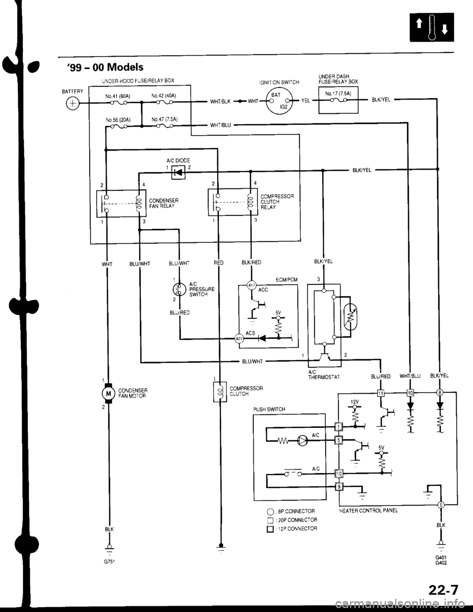
'99 - 00 Models
UNDER DASHFUSE/BELAY BOX
No.l7 (7.54)
BLK
I
G751
$*"
O :8P coNNEcToF
n :20P CONNECToF
E 12P coNNEcroRBLK
d-
G401G402
UNDER HOOD FUSE/RELAY 8OX
N0.41 (P,0A) N0.42 (404)
COMPRESSORCLUTCHFELAY
GNITON SWTCH
HEATER CONTROL PANEL
22-7
Page 1443 of 2189
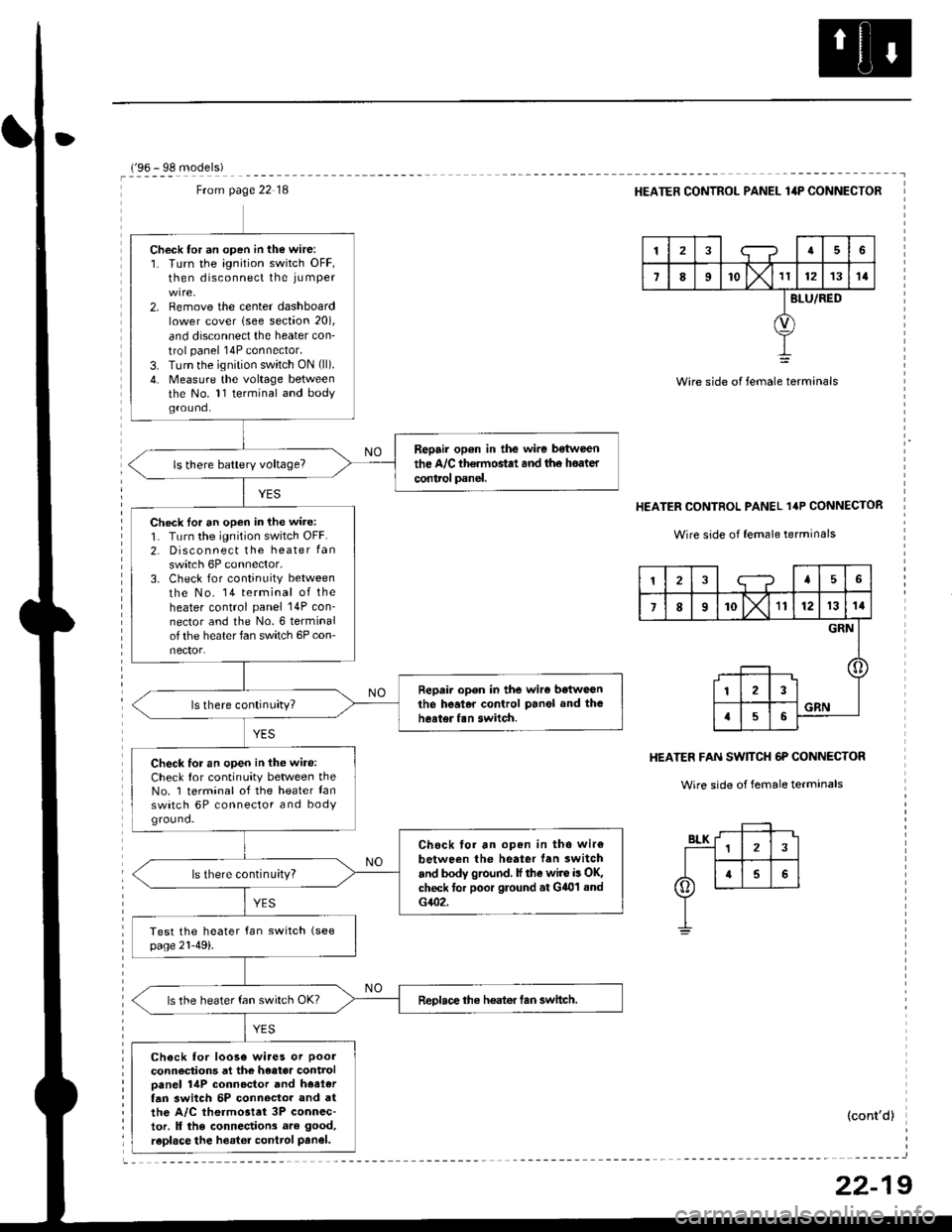
Ftom page 22 18
Check tor an open in the wire:1. Turn the ignition switch OFF,then disconnect the iu mper
2. Remove the center dashboardlower cover lsee section 20),
and disconnect the heater con'
trol panel 14P connector.
3. Turn the ignition switch ON (ll).
4. Measure the voltage betweenthe No. 11 terminal and bodyground.
Repair op6n in the wire bstween
the A/C th€rmostat and th6 hoater
control panel.
Check lor an open in the wire:
1. Turn the ignition switch OFF.2. Disconnect the heater Ian
switch 6P connector,3. Check for continuity between
the No. 14 terminal of theheater control panel 14P con_nector and the No.6 terminalof the heater fan switch 6P con-nector.
Repair open in the wiro betweGnthe heal.r control Panel and theheater fan switch.
Check for an open in thG wire:Check for continuity between theNo. 1 terminal of the heater lanswatch 6P connector and bodYground.
Chock tor an open in tho wir€
between the heater lan switch
and body ground. lf the wire is OK,check for poor ground at G401 sndG402.
ls there continu;ty?
ReDlace the heater tan switch.ls the heater fan switch OK?
Check for loose wiaes or poor
connections at the heater controloanel 14P connoctor and hoetertan 3witch 5P conn€clor and atthe A/C thermostet 3P connec-tor. ll the connections are good,
raplace the heator control Panel.
r'oA - qe m^.lalal
HEATER CONTROL PANEL lilP CONNECTOR
tra6
7II'o lx't1121314
BLU/RED
Wire side of female terminals
HEATER CONTROL PANEL 1'P CONNECTOR
Wire side of female terrninals
HEATER FAN SW]TCH 6P CONNECTOR
Wire side of female terminals
(cont'd)
12;--?45
7I10X'll121314
GRN
123
a56GRN
22-19
Page 1444 of 2189
Troubleshooting
('99 00 models)
From page 22 18
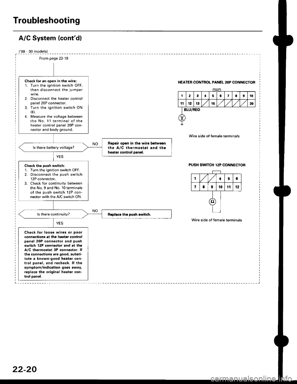
Check lor an open in the wire:1. Turn the ignition switch OFF,then disconnect the ju mper
2. Disconnect the heater controlpanel 20P connector.3. Turn the ;gnition switch ON{
i.4. Measure the voltage betweenthe No. 11 terminal of theheater control panel 20P con-nector and body ground.
Ropai. opan in tho wira batwaonthe A/C thermostat and thehoater control oanol.ls there battery voltage?
Check the push switch:1. Turn the ignition switch OFF.2. Disconnect the push switch12P connector.3. Check for continuity betweenthe No. I and No. 10 terminalsof the push switch 12P con-nector with the A/C switch ON.
Check for loose wi.es or poor
connections el the hgater controlpanel 20P connector and pushswitch 12P connector and at theA/C thermostat 3P connector. Ittha connections are good, substi-tute a known-good heatea con-trol pan€|, and recheck. lf thesymptom/indication goe3 away,replace lhe original healer con-trol oan€|,
HEATER CONTROL PANEL anP CONNECTOR
Wire side of temale terminals
PUSH SW]TCH 12P CONNECTOR
Wire side of female terminals
,/1,/156
7819t01112
I
I
I
Page 1446 of 2189
A/C Service Tips and Precautions
The air conditioner system uses HFC-134a (R-134a) refrigerant and polyalkyleneglycol (PAG) refrigerant oil*, which are not
compatible with CFC-12 (R-12) refrigerant and mineral oil. Do not use R-12 refrigerant or mineral oil in this system, and do
not attempt to use R-12 servicing equipmenU damage to the air conditioner system or your servicing equipment will result.*Sanden SP-10:
. P/N 38897 - P13 - A0lAH: 120 ml 14ll.oz, 4.2lmp.oz)
. P/N 38899 - P13 - A0l | 40 mf 11 1/3ll.oz,1.4 lmp'oz)
Use only service equipment that is U.L. listed and is certified to meet the requirements of SAE J2210 to remove R 134a
from the air conditioner system.
CAUTION: Exposure to air conditioner ref;ige;ant and lubricant vapol or mist can irritate syes, nose and throat, Avoid
breathing the air conditioner refrigerant and lubricant vapor or misl.
lf accidental system discharge occurs, ventilate work area before resuming service.
R-'134a service equipment or vehicle air conditioner systems should not be pressure tested or leak tested with compressed
ai.
!@@ some mixtures of air and R-t3ila have been shown to be combustible at elevated pressures and can result
in tire or explosion causing iniury or property damage. Never use compressed air lo pressure tesl R-134a service equip-
ment or vehicle 8ir conditioner systoms.
Additional health and safety information may be obtained from the refrigerant and Iubricant manufacturers.
L Always disconnect the negative cable from the battery whenever replacing air conditioning pans.
2. Keep moisture and dust out of the system. When disconnecting any lines, plug or cap the fittings immediately; don't
remove the caps or plugs until just before you reconnect each line.
3. Before connecting any hose or line, apply a few drops of refrigerant oilto the O-ring.
4, When tightening o. loosening a fitting, use a second wrench to support the matching fitting.
5. When discharging the system, use a R-134a refrigerant recovery/recycling/charging station; don't release refrigerant
into the atmosphere,
6. Add refrigerant oil after replacing the following parts:
NOTE:
. To avoid contamination, do not return the oil to the container once dispensed, and never mix it with other refriger-
ant oils.
. lmmediately after using the oil, replace the cap on the container, and seal it to avoid moisture absorption.
. Do not spill the refrigerant oil on the vehicle; it may damage the paint; if the refrigerant oil contacts the paint, wash
it off immediately.
Condenser .......2o ml (2/3 fl.oz, 0.7 lmp.ozl
Evaporator .,.,.,. i[5 m{ 11 213 tl.oz,1,6lmp.ozl
Line or hose ..... 10 mf (1/3 fl.oz, 0.4 lmp.ozl
Receiver/Dryer 10 m{ (1/3 fl.oz,0.'l lmp.ozl
Leakage repair 25 m{ (5/6 fl.oz, 0.9 lmp.ozl
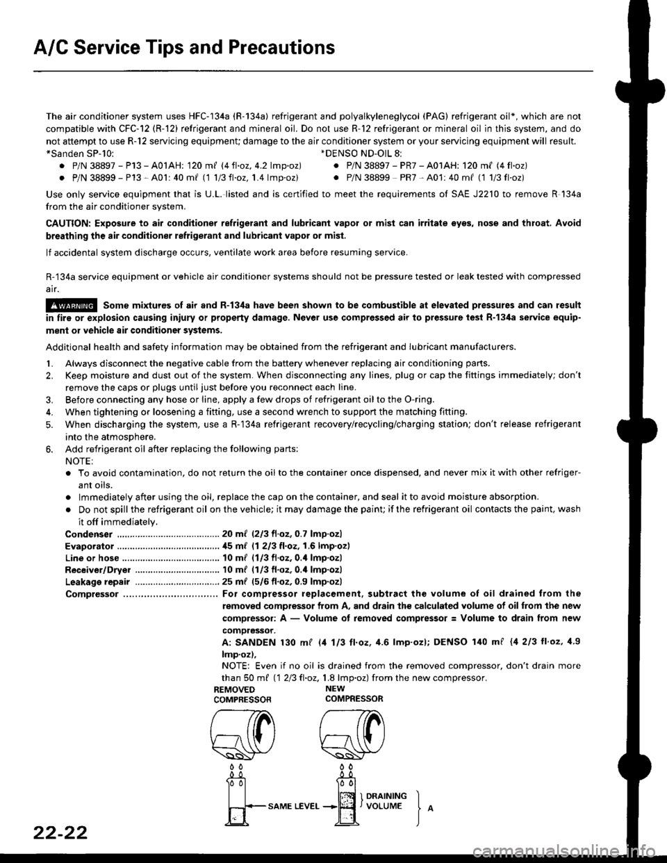
Comptessor ... For compressor replacement. subtract the volume of oil drained trom the
removed compressor from A, and drain the calculated volume of oilfrom the new
compressor: A - Volume of removed compressor: Volume to drain from new
comoressor.
A: SANDEN 130 mf l/t 113 ll.oz, 4.6 lmp'ozl; DENSO 140 mf {4 213 ll'oz, 1.9
lmp.oz),
NOTE: Even if no oil is drained from the removed compressor, don't drain more
than S0 m{ 112Ell.oz,1.8 lmp.oz) fromthe new compressor.
REMOVED NEW
COMPRESSORCOMPRESSOR
*DENSO ND-OlL 8l
. P/N 38897 - PR7 - A01AH: 120 ml (4 fl.oz)
. P/N 38899 PR7-A01:40mf (1 1/3fl'oz)
rereW W0000
22-22
-0_!- -0_a
Tol l00l
| | lffi 1 onrrrutrc I
fi+-sAME
LEvEr...+jEf,voLUME
J
^
Page 1450 of 2189
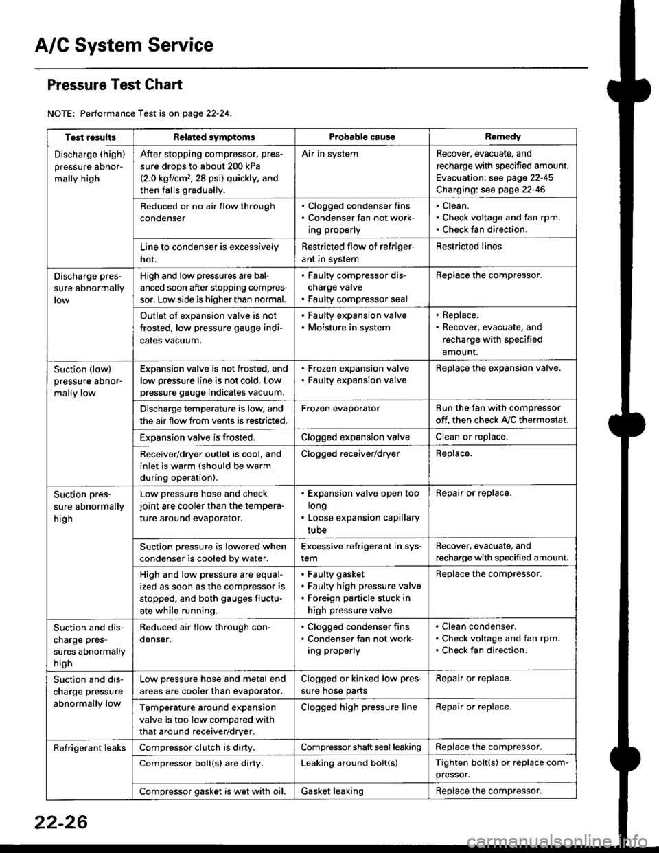
A/C System Service
Pressure Test Chart
NOTE: Performance Test is on page 22-24,
Test resultsRelated symptomsProbabl€ causeRemedy
Discharge (high)
pressure aDnor-
mally high
After stopping compressor. pres-
sure drops to about 200 kPa
{2.0 kgflcm,,28 psi) quickly, and
then falls gradually.
Air in systemRecover, evacuate, and
recharge with specified amount.
Evacuation: see page 22-45
Charging: see page 22-46
Reduced or no air flow through
condenser
. Clogged condenser fins. Condenser fan not work-
ing properly
Clean.
Check voltage and fan rpm.
Check fan direction.
Line to condenser is excessively
hot.
Restricted flow of refriger-
ant in system
Restricted lines
Discharge pres-
sure abnormally
High and low pressures are bal-
anced soon after stopping compres-
sor, Low side is higher than normal.
. Faulty compressor dis-
charge valve. Faulty compressor seal
Replace the compressor.
Outlet of expansion valve is not
frosted, low pressure gauge indi-
cales vacuum.
. Faulty expansion valve. Moisture in system
. Replace,. Recover, evacuate, and
recharge with specified
amount.
Suction (low)
pressure abnor-
mally low
Expansion valve is not frosted, and
low oressure line is not cold. Low
pressure gauge indicates vacuum.
. Frozen expansion valve. Faulty expansion valve
ReDlace the exoansion valve.
Discharge temperature is low. and
the air flow from vents is restricted.
Frozen evaporatorRun the fan with compressor
off. then check A,/C thermostat.
Exoansion valve is frosted.Clogged expansion valveClean or replace.
Receiver/dryer outlet is cool, and
inlet is warm (should be warm
during operation).
Clogged receiver/dryerReplace.
Suction pres-
sure abnormally
hig h
Low pressure hose and check
joint are cooler than the tempera-
ture around evaporator.
. Expansion valve open too
long. Loose expansion capillary
tube
Repair or replace.
Suction oressure is lowered when
condenser is cooled bv water.
Excessive refrigerant in sys-
tem
Recover. evacuate, and
recharge with specified amount.
High and low pressure are equal-
ized as soon as the compressor is
stopped, and both gauges fluctu-
ate while running.
Faulty gasket
Faulty high pressure valve
Foreign particle stuck in
high pressure valve
Replace the compressor.
Suction and dis-
charge pres-
sures abnormally
h igh
Reduced air flow through con-
denser.
. Clogged condenser fins. Condenser fan not work-
ing properly
Clean condenser.
Check voltage and fan rpm.
Check fan direction.
Suction and dis-
charge pressure
abnormally low
Low pressure hose and metal end
areas are cooler than evaporator.
Clogged or kinked low pres-
sure hose parts
Repair or replace.
Temperature around expansion
valve is too low compared with
that around receiver/dryer.
Clogged high pressure lineRepair or replace.
Refrigerant leaksCompressor clutch is diny,Compressor shaft seal leakingReplace the compressor.
Compressor bolt{s) are diny.Leaking around bolt(s)Tighten bolt(s) or replace com-
pressor.
Compressor gasket is wet with oil.Gasket leakingReplace the compressor.
22-26
Page 1453 of 2189
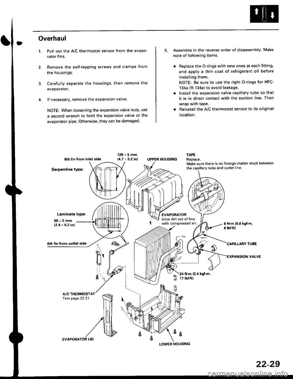
Overhaul
1.
3.
Pull out the A,/C thermostat sensor from the evapo-
rator fins.
Remove the self-tapping screws and clamps from
the housings.
Carefully separate the housings, then remove the
evaporator.
lf necessary, remove the expansion valve.
NOTE: When loosening the expansion valve nuts, use
a second wrench to hold the expansion valve or the
evaporator pipe. Otherwise, they can be damaged
5. Assemble in the reverse order of disassembly Make
note of following items.
. Replace the O-rings with new ones at each fitting,
and apply a thin coat of refrigerant oil before
installing them.
NOTE: Be sure to use the right O-rings for HFC-
134a (R-134a) to avoid leakage.
. Install the expansion valve capillary tube so that
it is in direct contact with the suction line. Then
wrap wath taPe.
. Reinstall the Ay'C thermostat sensor to its original
location.
6th tin lrom inld side
Serpentine type:
Laminate typo:
TAPEReplace.lvake sure there is no foreign matter stuck between
60t5mml'2.1! O.2 inl
EVAPORATORblow din out of linswith compressed air,
HOUSING
8 N.m 10.8 kgt m,6 tbf.ftl
6th fin lrom outle't sideCAPILLARY TUAE
VALVEN
u'
ll
6\N.m (2.it kgt.m,17 tbtftl1l
A/C THERMOSTfesr page 22 21
%
EVAPORA
LOWER
22-29
Page 1474 of 2189
Troubleshooting
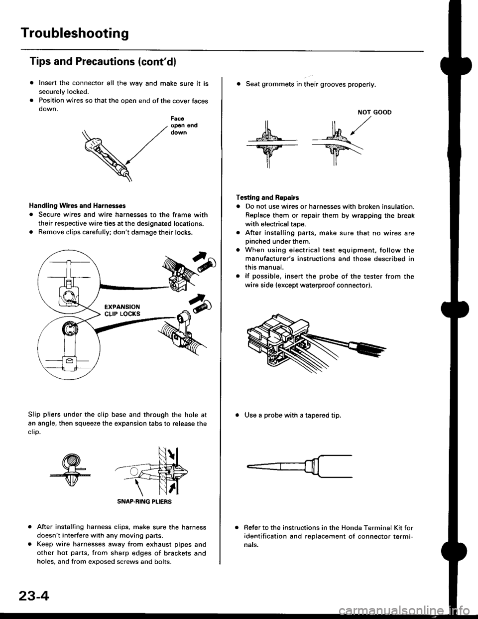
Tips and Precautions (cont'dl
Insert the connector all the way and make sure it is
securelv locked.
Position wires so that the open end of the cover faces
down.
After installing harness clips, make sure the harness
doesn't interfere with any moving pans.
Keep wire harnesses away from exhaust pipes and
other hot parts. from sharp edges of brackets and
holes, and from exDosed screws and bolts.
V
F6c6op€n end
Handling Wires and Harnosscs
. Secure wires and wire harnesses to the frame with
their respective wire ties at the designated locations,
. Remove clips carefully; don't damage their locks.
Slip pliers under the clip base and through the hole at
an angle, then squeeze the expansion tabs to release the
clrp.
SNAP-BING PLIERS
23-4
NOT GOOO
ll il,/
s*' -.1}8."/_Y--_Y5\
il ,,
Testing and Repairs
o Do not use wires or harnesses with broken insulation.
Replace them or repair them by wrspping the break
with electricaltaoe.
. After installing parts, make sure that no wires arepinched under them.. When using electrical test equipment, follow the
manufacturer's instructions and those described in
this manual.
. lf possible, insert the probe of the tester from the
wire side (except waterproof connector).
. Seat grommets in their grooves properly.
. Use a probe with a tapered tip.
Refer to the instructions in the Honda Terminal Kit for
identification and replacement of connector termi-
nats.
Page 1486 of 2189

Connector ldentification and Wire Harness Routing
Engine Wire Harness lD16Y5, D16Y8 enginss): '96 - 98 models
Connector or
Torminal
Numbsr of
CavitissLocationConnects toNot€s
c 101c102c103c104c104c105c106c107c108c 109c110c111c112c113c114c115c116cl17c118c119c120cl21
c122c123cl23c124
c125
c127c12Ac129c130c131c132c 133c134c135
c136
c138c139c140c 141c142c 143c144cl44c145c'146cl47
10
1
22
14l4322l0I
2
2
2
2120
3l
14
14
1222
2
2
22
Left side of engine compartmentMiddle of engineMiddle of engineLeft side of engine companmentLeft side of engine compartmentMiddle of engineMiddle of engineMiddle of engineMiddle of engineMiddle of enginefvliddle of engineMiddle of engineMiddle of engineMiddle of engineMiddle of engineMiddle of engineMiddle of engineLeft side of engine compartmentMiddle of engineMiddle of engineMiddle of engineMiddle of engine
Middle of engineMiddle of engineMiddle of engineMiddle of engineMiddle of engineMiddle of engineMiddle of engineMiddle of engineMiddle of engineRight side of engine companmentBehind right kick panelUnder right side of dashUnder riOht side of dashUnder right side of dashUnder right side of dashUnder right side of dashUnder right side of dash
Under right side of dash
Under right side of dash
Middle of engineMiddle ot enginel iddle of engineMiddle of engineMiddle of ongineMiddle of engineLeft side of engine compartmentMiddle of engineMiddle of engineRight side of engine compartmentRight side of engine compartmentRight side of engine compartment
USACanada
Afi
USA
-' (A/r)
Main wire harness (C303)Crankshaft speed fluctuation (CKF) sensorEngine oil pressure switchAlternatorAlternatorNo. 'l fuel injectorNo. 2 fuel injectorNo.3 fuel injectorNo. 4 fuel injectorIAC valveThrottle position (TP) sensorl\4anifold absolute pressure (MAP) sensorIntake air temperature (lAT) sensorPower steering pressure {PSPI switchEVAP purge control solenoid valveJunction connectorJunction conn€ctorVehicle speed sensor {VSS}Countershaft speed sensorEngine coolant temp€rature (ECT) switch ADistributorEngine coolant temperature (ECT) sendingunrtEngine coolant temperature (ECT) sensorPrimary HO2S (sensor'l)Primary HO2S (sensor 1)Back-up light switchLock-up control solenoid valveSecondary HO2S (sensor 2)Mainshaft speed sensorLinear solgnoid valveShift control solsnoid valveStarter solenoidJunction connectorMain wire harnesE (C446)ECM/PCMPCMECMiPCMECM/PCMMain wire harness (C305)
Main wire harness (C305)
Main wire harness (C305)
Knock sensor (KS)IAC valveVTEC solenoid valveVTEC pressure switchEVAP control canister vent shut valveEGR control solenoid valveSecondary gear shaft speed sensorEGR valveEGR valveDrive pulley speed sensorSolenoid connector {CVT)Driven pulley speed sensor
*, (M/T)M/T*" INT\
*, tAtf)
NT:'96 model*,(A,/T):'97 - 98mooets
moqets
M/T
-1 (l,/T)*, (A,/T)-,(4,/T)*1 {M/T)*, (A,/T)*1 (CW)*, (A,T)
T101r102Left side of engine companmentRight side of engine companmentAlternatorUnder-hood fuse/relay boxG 101Middle of engineEngine ground, via engine wire harness
2
*1: Dl6Y5 engine*2: D16Y8 engine*3: D16Y5 (Ay'T), D16Y8 engines
3-16